
Imagine having your own compact weather station that continuously monitors the surrounding environment and presents the information on a beautiful touchscreen dashboard. Whether you are a hobbyist, student, or electronics enthusiast, building a weather monitoring system is an excellent way to learn about environmental sensing, embedded systems, and graphical user interfaces.
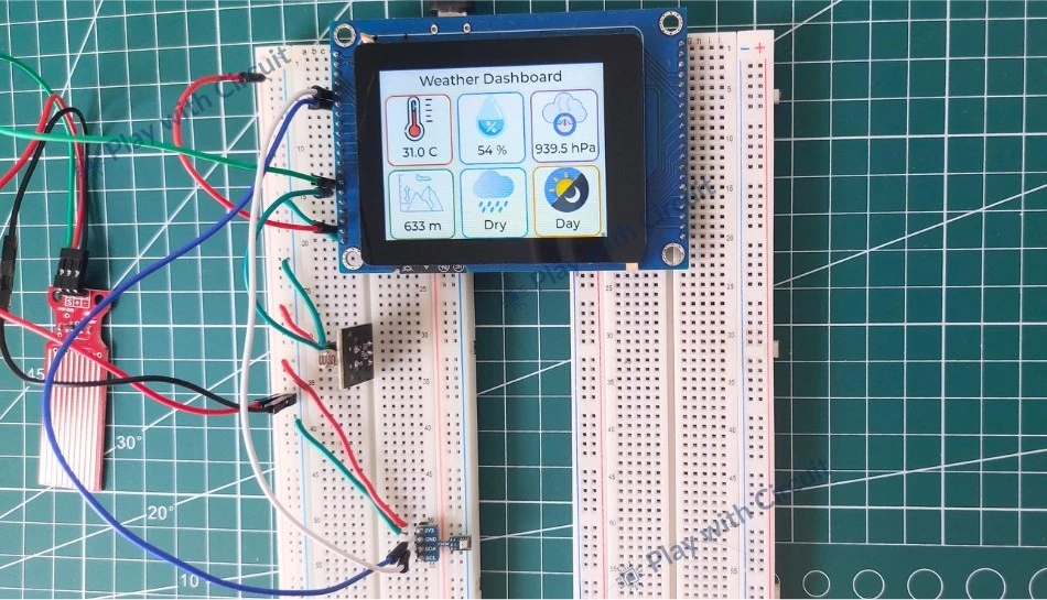
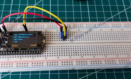
In this project, we will build a Smart Weather Monitoring System capable of measuring temperature, humidity, atmospheric pressure, altitude, rainfall status, and day/night conditions in real time. What makes this project unique is that it does not require a separate microcontroller board and display module. Instead, it utilizes the powerful VIEWE 2.8-inch ESP32-S3 Smart Display, which acts as both the processing and display unit. Environmental sensors including the BME280 sensor, Rain Sensor, and LDR sensor are directly interfaced with the smart display, resulting in a simple and compact hardware design.
One of the most interesting parts of this project is the use of the LVGL (Light and Versatile Graphics Library). Using the LVGL, the measured data is displayed on an interactive dashboard featuring weather icons and dynamically updated values.
By the end of this tutorial, you will not only have your own smart weather station but also gain hands-on experience with the ESP-IDF framework, sensor interfacing, and GUI development using LVGL. Let’s get started!
How does Weather Monitoring System Work?
Let’s understand how different sensors and the ESP32-S3 display module work together to collect, process, and display environmental data:
Collecting Environmental Data
The system uses following sensors to continuously monitor real-time weather conditions from the surroundings:
BME280 Sensor: The BME280 environmental sensor is a compact sensor that measures temperature, humidity, and atmospheric pressure with high accuracy. It can also be used to find altitude using pressure data. The module communicates with a microcontroller using the I2C interface and provides digitally calibrated measurements
Rain Sensor: The rain sensor detects the presence of water droplets on its conductive surface. When rainwater falls onto the sensor plate, the conductivity changes as water bridges the conductive tracks. The sensor output changes according to the amount of water detected, allowing the ESP32 to determine whether it is raining or dry.
Light Sensor: The light sensor detects ambient light intensity and helps determine whether it is daytime or nighttime. The sensor resistance changes according to light intensity:
- High light intensity → low resistance
- Low light intensity → high resistance
Processing the Sensor Data
The data is processed using the ESP32-S3 integrated inside the smart display module. It
- Reads sensor values in real time
- Converts raw sensor readings into meaningful information
- Calculates altitude from atmospheric pressure
- Detects weather conditions
- Display data on TFT display
Displaying Real-Time Weather Information
After processing the sensor data, the ESP32-S3 updates the graphical weather dashboard on the 2.8-inch TFT touchscreen display. The display interface is designed using the LVGL (Light and Versatile Graphics Library), which allows us to create weather icons.
The display continuously refreshes the sensor readings, allowing users to monitor live environmental conditions instantly.
LVGL (Lightweight Graphics Library)
LVGL is an open-source embedded graphics framework designed to create interactive graphical user interfaces (GUIs) on microcontrollers and smart displays. It provides various graphical components such as labels, buttons, images, and animations, allowing developers to design visually appealing dashboards.
In this system, LVGL is used to create the graphical dashboard displayed on the ESP32-S3 based smart display. It initializes the display and touch controller, creates weather information cards, and places icons and labels on the screen. Sensor readings obtained from the sensors are continuously updated using LVGL label objects.
Building the Weather Monitoring System
Now that we have understood the working of the Smart Weather Monitoring System, let’s start building it.
Hardware Requirements
| Component | Quantity | Purpose | Buy Now |
|---|---|---|---|
| ESP32 Display Module | 1 | Main controller and display unit | Viewe |
| 7Semi BME280 Sensor | 1 | Measures temperature, humidity, pressure, and altitude | 7Semi |
| Rain Sensor | 1 | Detects rain or water droplets | Amazon |
| Light Sensor | 1 | Detects ambient light intensity for day/night detection | Amazon |
| Jumper Wires | Multiple | For Connections | Amazon |
| Breadboard | 2 | For Prototyping | Amazon |
| USB Cable Type A to B Type | 1 | For programming Display | Amazon |
Software Requirements
- Visual Studio Code, v1.116.0 or above.
- ESP-IDF extension in VS Code, v1.11.1 or above.
- ESP-IDF version installed using extension in VS Code, v5.3.5.
- Python installed manually, v3.11.2
- BME280 library by Bosch; its files are included in the source code package.
- Other dependencies, like the LVGL port (v8.4.0) for the display, are included in the source code package.
❕Note
When you install any software, do not customize the path; install the software at the default path recommended by the installer.
Circuit Diagram for ESP32-Based Weather Monitoring System
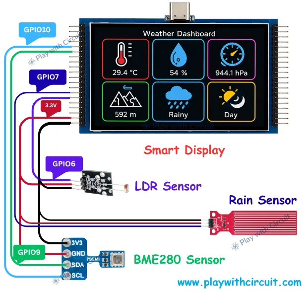
The above circuit diagram shows connections between 2.8-inch ESP32-S3 Smart Display Module and environmental sensors. The sensors used in this project are connected directly to the ESP32-S3 GPIO pins, allowing the system to collect real-time weather information and display it on the dashboard.
BME280 Sensor Connection
Since the BME280 supports I2C communication, it requires only two signal lines in addition to power connections. The sensor is connected to the ESP32-S3 using the dedicated I2C bus (I2C_NUM_1).
| BME280 Pin | ESP32-S3 Pin | Purpose |
|---|---|---|
| VCC | 3.3V | Power Supply |
| GND | GND | Ground |
| SDA | GPIO9 | I2C Data Line |
| SCL | GPIO10 | I2C Clock Line |
The SDA (Serial Data) line transfers sensor data to the ESP32-S3, while the SCL (Serial Clock) line provides synchronization for I2C communication. The ESP32 periodically reads sensor values and updates the weather dashboard with temperature, humidity, pressure, and altitude information.
Rain Sensor Connection
The Rain Sensor is connected with display using its analog output (AO).
| Rain Sensor Pin | ESP32-S3 Pin | Purpose |
|---|---|---|
| VCC | 3.3V | Power Supply |
| GND | GND | Ground |
| AO | GPIO7 | Analog Input |
The analog voltage generated by the rain sensor is continuously monitored using GPIO7 configured as ADC input pin. Based on the measured voltage level, the ESP32-S3 determines whether the sensor is dry or exposed to active rainfall and updates the rain status on the display.
LDR Sensor Connection
The resistance of the LDR changes according to the amount of light falling on its surface. The sensor module converts these resistance changes into a variable analog voltage that can be measured by the ESP32-S3.
| LDR Module Pin | ESP32-S3 Pin | Purpose |
|---|---|---|
| VCC | 3.3V | Power Supply |
| GND | GND | Ground |
| AO | GPIO6 | Analog Input |
The ESP32 continuously reads the analog voltage from GPIO6, configured as ADC input pin. Based on predefined threshold values, the software determines whether it’s day or night and updates the dashboard accordingly.
Power Distribution
All sensors in the system operate at 3.3V, which is supplied directly from the ESP32-S3 Smart Display module.
The power connections are shared among all sensors:
- BME280 VCC → 3.3V
- Rain Sensor VCC → 3.3V
- LDR Sensor VCC → 3.3V
Similarly, all sensor grounds are connected to the common GND pin of the display module. Sharing a common ground ensures accurate signal measurement and reliable communication between the sensors and the ESP32-S3.
Data Acquisition and Processing
Once powered, the ESP32-S3 continuously collects environmental data from all connected sensors:
- BME280 → Temperature, Humidity, Pressure, Altitude
- Rain Sensor → Rainfall Status
- LDR Sensor → Day/Night Detection
The acquired sensor data is processed in real time and displayed on the weather dashboard. The graphical interface presents the environmental information through weather icons, numerical readings, status indicators, and visual widgets, creating an intuitive and interactive weather monitoring experience.
Weather Monitoring System Code
The complete source code for the Smart Weather Monitoring System is provided in the accompanying ZIP file. Before proceeding, ensure that all the required software, and ESP-IDF tools mentioned in the software requirement section have been installed correctly on your system.
Opening the Project in Visual Studio Code
After extracting the ZIP file, you will find multiple folders and project files. However, you need to open only a specific project folder in Visual Studio Code.
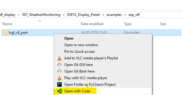
Navigate to the following directory:
007_WeatherMonitoring
└── ESP32_Display_Panel
     └── examples
          └── esp_idf
               └── lvgl_v8_port
In the folder path “007_WeatherMonitoring\ESP32_Display_Panel\examples\esp_idf”, right-click on the lvgl_v8_port folder and select “Open with Code” to launch the project in Visual Studio Code.
Cleaning the Project
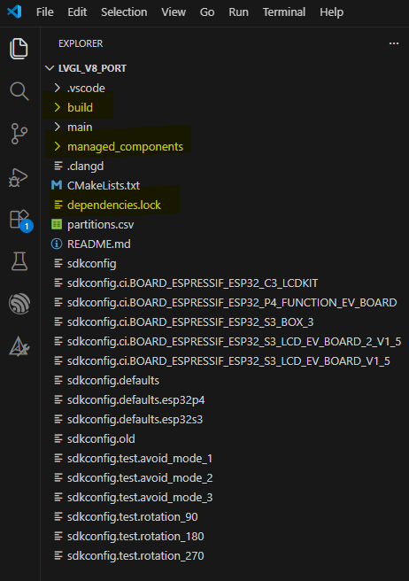
After opening the project, locate the following folders and files in the Project Explorer panel:
- build
- managed_components
- dependencies.lock
Delete these folders and files before building the project. This ensures that the project is compiled from a clean state and prevents issues caused by previously generated build files.
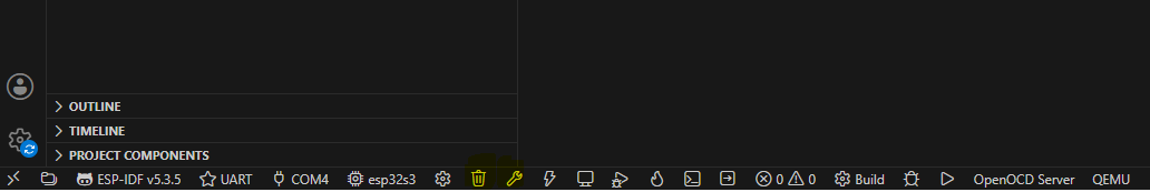
Next, use the ESP-IDF extension controls available in the VS Code status bar as shown below:
- Clean the project by clicking on bin icon
- After cleaning is completed, click the “bolt opener” icon near the bin icon.
- Wait for the build process to finish successfully.
If the ESP-IDF extension does not automatically detect the target device or COM port, manually configure the following settings:
- ESP32-S3 Target Device
- Serial COM Port
- ESP-IDF Toolchain
These options can be selected directly from the ESP-IDF status bar located at the bottom of the VS Code window.
Flashing the Firmware
After a successful build:
- Connect the ESP32-S3 Smart Display module to the computer using a USB Type-C cable.
- Click the Flash Device icon from the ESP-IDF toolbar and wait for the flashing process to complete.
- Once the upload is successful, the Smart Weather Monitoring dashboard will automatically start on the display.
Project Structure Overview
Although the project contains hundreds of files and folders related to the ESP-IDF framework, display drivers, LVGL libraries, and supporting components, only a few application files are directly related to the weather monitoring system.
The custom application code is primarily located inside the main folder.
main.cpp
The main.cpp file serves as the primary application entry point. Its key functions are:
- Initializes the ESP32-S3 Smart Display module.
- Configures the LVGL graphical user interface.
- Initializes the BME280 environmental sensor.
- Configures ADC channels for the rain sensor and LDR sensor.
- Reads temperature, humidity, pressure, and altitude values.
- Detects rain conditions using analog sensor data.
- Detects day/night conditions using ambient light measurements.
- Creates a graphical weather dashboard with icons and status cards.
- Continuously updates sensor values on the display in real time.
- Handles sensor communication errors and displays status accordingly.
This file controls how information is displayed and updated on the screen.
sensors.c
The sensors.c file contains all sensor-related functions and data acquisition routines. Its responsibilities include:
- Reading BME280 sensor data
- Measuring temperature values
- Measuring humidity values
- Reading atmospheric pressure
- Calculating altitude from pressure readings
- Reading rain sensor analog values
- Reading LDR sensor analog values
- Determining rain status
- Determining day/night status
- Providing processed sensor values to the user interface
This file acts as the sensor abstraction layer of the project and supplies real-time environmental data to the weather dashboard.
main.cpp Code
The code for the Smart Weather Monitoring System is developed using the ESP-IDF framework and LVGL graphics library. The program acquires environmental data from the connected sensors, processes the collected information, and displays the results on a graphical weather dashboard in real time. This program acts as the central controller of the weather monitoring system.
/*
Code for a weather Monitoring System to get data from different sensors and display it on a Smart IoT-based ESP32S3 Display
by playwithcircuit.com
*/

#include "esp_check.h"
#include "esp_display_panel.hpp"
#include "esp_lib_utils.h"
#include "lvgl.h"
#include "lvgl_v8_port.h"
#include "sensors.h"

using namespace esp_panel::drivers;
using namespace esp_panel::board;

// Declare external PNG image structures defined in separate C files
LV_IMG_DECLARE(temp);
LV_IMG_DECLARE(humidity);
LV_IMG_DECLARE(pressure);
LV_IMG_DECLARE(altitude);
LV_IMG_DECLARE(rain);
LV_IMG_DECLARE(light);

static char TAG[100];

// global character buffer
char buf[32];
E_STATUS eStatus;

// global label pointer
static lv_obj_t *temp_value_label;
static lv_obj_t *humidity_value_label;
static lv_obj_t *pressure_value_label;
static lv_obj_t *altitude_value_label;
static lv_obj_t *rainy_label;
static lv_obj_t *light_label;

// global value variables
float temp_value = 0;
unsigned char humidity_value = 0;
float pressure_value = 0;
unsigned int altitude_value = 0;
bool bIsRaining = false;
bool bIsDay = false;

// global card size
int card_w = 96;
int card_h = 100;

// static function for creating cards
static void create_card(lv_obj_t * parent,
                        int x,
                        int y,
                        int w,
                        int h,
                        const lv_img_dsc_t * icon,
                        const char * title,
                        const char * value,
                        lv_color_t border_color,
                        lv_obj_t ** value_label_out
                       )
{
    // card creation
    lv_obj_t * card = lv_obj_create(parent);

    lv_obj_set_size(card, w, h);

    lv_obj_set_pos(card, x, y);

    lv_obj_clear_flag(card,
                      LV_OBJ_FLAG_SCROLLABLE);

    // setting style
    lv_obj_set_style_radius(card, 12, 0);

    lv_obj_set_style_bg_color(card,
                              lv_color_hex(0xFFFFFF),
                              0);
    lv_obj_set_style_border_width(card,
                                  2,
                                  0);
    lv_obj_set_style_border_color(card,
                                  border_color,
                                  0);
    lv_obj_set_style_shadow_width(card,
                                  15,
                                  0);

    lv_obj_set_style_shadow_opa(card,
                                LV_OPA_20,
                                0);

    // creating image object
    lv_obj_t * img = lv_img_create(card);

    lv_img_set_src(img, icon);
    lv_obj_align(img,
                 LV_ALIGN_BOTTOM_MID,
                 0,
                 -20);

    // creating value label object
    lv_obj_t * value_label = lv_label_create(card);

    lv_label_set_text(value_label,
                      value);
    lv_obj_set_style_text_font(value_label,
                               &lv_font_montserrat_18,
                               0);
    lv_obj_set_style_text_color(value_label,
                                lv_color_hex(0x111111),
                                0);

    lv_obj_align(value_label,
                 LV_ALIGN_CENTER,
                 0,
                 30);

    // update out pointers for label values
    *value_label_out = value_label;
}
/*----------------------------------------------------------
    MAIN
----------------------------------------------------------*/
extern "C" void app_main(void)
{
    E_STATUS eRet_Status = eSTATUS_OK;
    Board *board = new Board();

    board->init();

    board->begin();

    lvgl_port_init(board->getLCD(), board->getTouch());

    /* Landscape */
    lv_disp_set_rotation(lv_disp_get_default(), LV_DISP_ROT_270);

    eRet_Status = BME280_SensorInit();
    if(eRet_Status != eSTATUS_OK)
    {
        ESP_LOGE(TAG, "Failed to Initialize BME280 Sensor");
        while(1){
            vTaskDelay(pdMS_TO_TICKS(10));
        }
    }

    eRet_Status = ADC_Init();
    if(eRet_Status != eSTATUS_OK)
    {
        ESP_LOGE(TAG, "Failed to Initialize ADC for Rain Sensor/LDR ");
        while(1){
            vTaskDelay(pdMS_TO_TICKS(10));
        }
    }

    lvgl_port_lock(-1);

    /*------------------------------------------------------
        SCREEN
    ------------------------------------------------------*/
    lv_obj_t * scr = lv_scr_act();

    lv_obj_set_style_bg_color(scr,
                              lv_color_hex(0xF3F4F6),
                              0);
    /*------------------------------------------------------
        HEADER
    ------------------------------------------------------*/
    lv_obj_t * header = lv_label_create(scr);

    lv_label_set_text(header,
                      "Weather Dashboard");

    lv_obj_set_style_text_font(header,
                               &lv_font_montserrat_20,
                               0);
    lv_obj_set_style_text_color(header,
                                lv_color_hex(0x111111),
                                0);

    lv_obj_align(header,
                 LV_ALIGN_TOP_MID,
                 0,
                 5);

    // first row
    create_card(scr,
                6,
                35,
                card_w,
                card_h,
                &temp,
                "Temperature",
                "27.0 C",
                lv_palette_main(LV_PALETTE_RED),
                &temp_value_label);

    create_card(scr,
                111,
                35,
                card_w,
                card_h,
                &humidity,
                "Humidity",
                "65 %",
                lv_palette_main(LV_PALETTE_BLUE),
                &humidity_value_label);

    create_card(scr,
                216,
                35,
                card_w,
                card_h,
                &pressure,
                "Pressure",
                "1008 hPa",
                lv_palette_main(LV_PALETTE_PURPLE),
                &pressure_value_label);

    // second row
    create_card(scr,
                6,
                140,
                card_w,
                card_h,
                &altitude,
                "Altitude",
                "125 m",
                lv_palette_main(LV_PALETTE_GREEN),
                &altitude_value_label);

    create_card(scr,
                111,
                140,
                card_w,
                card_h,
                &rain,
                "Rain",
                "Dry",
                lv_palette_main(LV_PALETTE_CYAN),
                &rainy_label);

    create_card(scr,
                216,
                140,
                card_w,
                card_h,
                &light,
                "Light",
                "Day",
                lv_palette_main(LV_PALETTE_ORANGE),
                &light_label);

    lvgl_port_unlock();
    while (1)
    {
        eStatus =  getBME280Data(&temp_value, &humidity_value, &pressure_value, &altitude_value);
        if(eStatus == eSTATUS_OK)
        {
            sprintf(buf, "%.1f C",temp_value);
            lvgl_port_lock(-1);
            lv_label_set_text(temp_value_label, buf);
            lvgl_port_unlock();

            sprintf(buf, "%u %%",humidity_value);
            lvgl_port_lock(-1);
            lv_label_set_text(humidity_value_label, buf);
            lvgl_port_unlock();

            sprintf(buf, "%.1f hPa",pressure_value);
            lvgl_port_lock(-1);
            lv_label_set_text(pressure_value_label, buf);
            lvgl_port_unlock();

            sprintf(buf, "%u m",altitude_value);
            lvgl_port_lock(-1);
            lv_label_set_text(altitude_value_label, buf);
            lvgl_port_unlock();
        }
        else
        {
            lvgl_port_lock(-1);
            lv_label_set_text(temp_value_label, "ERROR");
            lvgl_port_unlock();

            lvgl_port_lock(-1);
            lv_label_set_text(humidity_value_label, "ERROR");
            lvgl_port_unlock();

            lvgl_port_lock(-1);
            lv_label_set_text(pressure_value_label, "ERROR");
            lvgl_port_unlock();

            lvgl_port_lock(-1);
            lv_label_set_text(altitude_value_label, "ERROR");
            lvgl_port_unlock();
        }

        eStatus =  getRainStatus(&bIsRaining);
        if(eStatus == eSTATUS_OK)
        {
            sprintf(buf,"%s", bIsRaining ? "Rainy" : "Dry");
            lvgl_port_lock(-1);
            lv_label_set_text(rainy_label, buf);
            lvgl_port_unlock();
        }
        else
        {
            lvgl_port_lock(-1);
            lv_label_set_text(rainy_label, "ERROR");
            lvgl_port_unlock();
        }

        eStatus =  getLightStatus(&bIsDay);
        if(eStatus == eSTATUS_OK)
        {
            sprintf(buf,"%s", bIsDay ? "Day" : "Night");
            lvgl_port_lock(-1);
            lv_label_set_text(light_label, buf);
            lvgl_port_unlock();
        }
        else
        {
            lvgl_port_lock(-1);
            lv_label_set_text(light_label, "ERROR");
            lvgl_port_unlock();
        }
        vTaskDelay(pdMS_TO_TICKS(10));
    }
}
Code Explanation
Header File Inclusion
First, we include header files that provide access to different software components required by the application.
esp_check.h provides ESP-IDF error-checking macros and debugging utilities. It simplifies error handling during peripheral initialization.
esp_display_panel.hpp contains the display driver abstraction layer for the ESP32-S3 smart display. It provides APIs for LCD initialization, display configuration, and touch controller management.
esp_lib_utils.h provides utility functions used internally by the display framework.
lvgl.h is the main header file of the LVGL graphics library. It provides all GUI-related functions such as object creation, styling, image rendering, and event handling.
lvgl_v8_port.h acts as a bridge between LVGL and ESP-IDF. It configures display buffers, refresh callbacks, and synchronization mechanisms required by LVGL.
sensors.h contains prototypes for all sensor-related functions.
#include "esp_check.h"
#include "esp_display_panel.hpp"
#include "esp_lib_utils.h"
#include "lvgl.h"
#include "lvgl_v8_port.h"
#include "sensors.h"
Namespace Declaration
The using namespace statements import the driver and board namespaces from the ESP Display Panel library, allowing direct access to display-related classes and functions without repeatedly writing the full namespace name. This improves code readability and simplifies hardware initialization within the application.
using namespace esp_panel::drivers;
using namespace esp_panel::board;
Image Resource Declaration
LVGL stores images as C structures generated from PNG files. These declarations inform the compiler that image descriptors exist in separate source files. Each descriptor contains: Image dimensions, Color depth, Pixel data and Compression information.
// Declare external PNG image structures defined in separate C files
LV_IMG_DECLARE(temp);
LV_IMG_DECLARE(humidity);
LV_IMG_DECLARE(pressure);
LV_IMG_DECLARE(altitude);
LV_IMG_DECLARE(rain);
LV_IMG_DECLARE(light);
Global Variables and Label
Now we define following variables:
TAG is used for logging and debugging messages in the ESP-IDF framework.
buf is a character buffer used to format sensor values before displaying them on the screen.
eStatus stores the return status of sensor and peripheral functions to verify successful execution.
We use pointers to LVGL label objects that display weather information on the dashboard. Storing the label addresses globally allows the application to update sensor values dynamically without recreating the GUI elements each time the data changes.
static char TAG[100];

// global character buffer
char buf[32];
E_STATUS eStatus;

// global label pointer
static lv_obj_t *temp_value_label;
static lv_obj_t *humidity_value_label;
static lv_obj_t *pressure_value_label;
static lv_obj_t *altitude_value_label;
static lv_obj_t *rainy_label;
static lv_obj_t *light_label;
Global Value Variables
Next, we declare global variables to store the latest sensor readings obtained from the BME280, rain sensor, and LDR sensor. They act as global data containers that are continuously updated during program execution.
Next, we define the width and height of each weather information card displayed on the LVGL dashboard.
temp_valuestores temperature in °C.humidity_valuestores relative humidity in %.pressure_valuestores atmospheric pressure in hPa.altitude_valuestores altitude in meters.bIsRainingstores the rain status (Rainy/Dry).bIsDaystores the light status (Day/Night).
// global value variables
float temp_value = 0;
unsigned char humidity_value = 0;
float pressure_value = 0;
unsigned int altitude_value = 0;
bool bIsRaining = false;
bool bIsDay = false;

// global card size
int card_w = 96;
int card_h = 100;
The following function creates a weather information card on the LVGL dashboard. It is a reusable function that generates cards for displaying temperature, humidity, pressure, altitude, rain status, and light status.
The function accepts parameters such as the parent screen object, card position (x, y), dimensions (w, h), weather icon, initial value, border color, and a pointer to the value label. By passing different parameters, the same function can create multiple cards with different content while maintaining a consistent user interface design.
// static function for creating cards
static void create_card(lv_obj_t * parent,
                        int x,
                        int y,
                        int w,
                        int h,
                        const lv_img_dsc_t * icon,
                        const char * title,
                        const char * value,
                        lv_color_t border_color,
                        lv_obj_t ** value_label_out
                       )
Next, we create a card object that acts as a container for displaying weather information on the dashboard. The card is positioned at the specified coordinates and sized according to the width and height parameters passed to the function.
After creating the card, various visual styles are applied, including rounded corners, a white background, colored borders, and shadow effects. These styling properties enhance the appearance of the user interface and provide a modern dashboard-like look. The card’s scrolling functionality is disabled since it is intended to display static weather information
Next, an image object is created inside the card and assigned the corresponding weather icon, such as temperature, humidity, pressure, altitude, rain, or light status. The icon is then aligned within the card to maintain a consistent layout across all dashboard elements.
Functions Used:
lv_obj_create() creates a new card object.lv_obj_set_size() sets the card dimensions.lv_obj_set_pos() positions the card on the display.lv_obj_clear_flag() disables card scrolling.lv_obj_set_style_*() applies visual styling properties.lv_img_create() creates an image object inside the card.lv_img_set_src() assigns the weather icon.lv_obj_align() positions the icon within the card.
{
    // card creation
    lv_obj_t * card = lv_obj_create(parent);

    lv_obj_set_size(card, w, h);

    lv_obj_set_pos(card, x, y);

    lv_obj_clear_flag(card,
                      LV_OBJ_FLAG_SCROLLABLE);

    // setting style
    lv_obj_set_style_radius(card, 12, 0);

    lv_obj_set_style_bg_color(card,
                              lv_color_hex(0xFFFFFF),
                              0);
    lv_obj_set_style_border_width(card,
                                  2,
                                  0);
    lv_obj_set_style_border_color(card,
                                  border_color,
                                  0);

   lv_obj_set_style_shadow_width(card,
                                  15,
                                  0);

    lv_obj_set_style_shadow_opa(card,
                                LV_OPA_20,
                                0);

    // creating image object
    lv_obj_t * img = lv_img_create(card);

    lv_img_set_src(img, icon);

    lv_obj_align(img,
                 LV_ALIGN_BOTTOM_MID,
                 0,
                 -20);
Creating and Configuring the Value Label
Next, we create a text label inside the weather card to display the sensor value. The label is initialized with a default value and styled using the Montserrat font and a dark text color to improve readability.
The label is then positioned near the center of the card, below the weather icon, ensuring a consistent layout across all dashboard cards.
value_label_out stores the address of the label object in a global pointer, enabling real-time updates of weather parameters throughout the execution of the program.
Functions Used:
lv_label_create() creates a text label object inside the cardlv_label_set_text() sets the initial text displayed on the labellv_obj_set_style_text_font() configures the font used by the labellv_obj_set_style_text_color() sets the text colorlv_obj_align() positions the label within the card
 // creating value label object
    lv_obj_t * value_label = lv_label_create(card);

    lv_label_set_text(value_label,
                      value);
    lv_obj_set_style_text_font(value_label,
                               &lv_font_montserrat_18,
                               0);

    lv_obj_set_style_text_color(value_label,
                                lv_color_hex(0x111111),
                                0);

    lv_obj_align(value_label,
                 LV_ALIGN_CENTER,
                 0,
                 30);

    // update out pointers for label values
    *value_label_out = value_label;
}
Main Function and System Initialization
The app_main() function is the starting point of the application in the ESP-IDF framework. It is automatically executed when the ESP32-S3 powers up and initializes the display, sensors, and graphical user interface.
The extern “C” declaration ensures that the ESP-IDF runtime can correctly identify and execute the app_main() function by disabling C++ name mangling.
Next, we create a Board object to access the ESP32-S3 Smart Display hardware. The init() and begin() functions initialize the display controller, touch controller, communication interfaces, and other board-specific resources required for system operation.
Next, we initialize the LVGL graphics library using lvgl_port_init and link it with the LCD display and touch controller drivers. After this step, the application can create and manage graphical objects such as labels, images, and dashboard cards.
Next, we configure the display to operate in landscape mode by rotating the default display by 270 degrees. This orientation provides a wider workspace for arranging the weather dashboard components.
Next, we initialize the BME280 environmental sensor using BME280_SensorInit() and establish I2C communication with the ESP32-S3. During initialization, the sensor is detected and configured for measurements.
The return status is checked to verify successful sensor initialization. If initialization fails, the application logs an error message and stops execution. ESP_LOGE function prints an error message to the serial monitor.
The ADC_Init() function configures the Analog-to-Digital Converter (ADC) channels used by the Rain Sensor and LDR Sensor. Since both sensors provide analog voltage outputs, the ADC converts these voltages into digital values.
After initialization, the return status is checked to ensure that the ADC channels have been configured successfully. If an error occurs, the system logs the failure and stops execution to avoid incorrect sensor readings.
Next, the application acquires an LVGL lock before creating or updating graphical objects. This ensures that only one task can access the LVGL graphics engine at a time, preventing display corruption.
extern "C" void app_main(void)
{
    E_STATUS eRet_Status = eSTATUS_OK;
    Board *board = new Board();

    board->init();
    board->begin();

    lvgl_port_init(board->getLCD(), board->getTouch());

    /* Landscape */
    lv_disp_set_rotation(lv_disp_get_default(), LV_DISP_ROT_270);

    eRet_Status = BME280_SensorInit();
    if(eRet_Status != eSTATUS_OK)
    {
        ESP_LOGE(TAG, "Failed to Initialize BME280 Sensor");
        while(1){
            vTaskDelay(pdMS_TO_TICKS(10));
        }
    }

    eRet_Status = ADC_Init();
    if(eRet_Status != eSTATUS_OK)
    {
        ESP_LOGE(TAG, "Failed to Initialize ADC for Ranin Sensor/LDR ");
        while(1){
            vTaskDelay(pdMS_TO_TICKS(10));
        }
    }

    lvgl_port_lock(-1);
Screen Creation and Background Configuration
The lv_scr_act() function returns a pointer to the currently active LVGL screen. This screen acts as the main container on which all graphical objects are created.
The function lv_obj_set_style_bg_color() sets the background color of the active screen. Here, a light gray color (#F3F4F6) is used to create a clean and modern dashboard appearance.
 lv_obj_t * scr = lv_scr_act();

    lv_obj_set_style_bg_color(scr,
                              lv_color_hex(0xF3F4F6),
                              0);
Header Creation
Here, we create the header of the weather dashboard and configure its appearance on the display.
First, we use the lv_label_create() function to create a text label object on the active screen. The lv_label_set_text() function then assigns the title “Weather Dashboard”, which serves as the main heading of the user interface.
To improve readability and visual appeal, the lv_obj_set_style_text_font() function applies the Montserrat font with a larger font size, while lv_obj_set_style_text_color() sets the text color to a dark shade. Finally, the lv_obj_align() function positions the header at the top-center of the screen.
  lv_obj_t * header = lv_label_create(scr);

    lv_label_set_text(header,
                      "Weather Dashboard");

    lv_obj_set_style_text_font(header,
                               &lv_font_montserrat_20,
                               0);
    lv_obj_set_style_text_color(header,
                                lv_color_hex(0x111111),
                                0);

    lv_obj_align(header,
                 LV_ALIGN_TOP_MID,
                 0,
                 5);
Creating the First Row of Weather Cards
In this section, we create the first row of the weather dashboard, which displays Temperature, Humidity, and Atmospheric Pressure information. The create_card() function is called three times with different parameters to generate individual cards for each weather parameter. Although the card layout remains the same, each card is configured with a unique icon, default value, border color, and label pointer.
The first card displays temperature information using the temperature icon, an initial value of 27.0 °C, and a red border. Similarly, the second card displays humidity information with a blue border and a default value of 65%, and the third card displays atmospheric pressure with a purple border and an initial value of 1008 hPa.
The create_card() function uses the screen object (scr) as the parent container and positions each card at specific coordinates to create a horizontal row layout.
The parameters card_w and card_h define a uniform size for all cards. The lv_palette_main() function is used to assign predefined LVGL colors to the card borders.
Finally, pointers such as temp_value_label, humidity_value_label, and pressure_value_label store references to the value labels within each card, allowing the application to update the displayed sensor readings at runtime.
    // first row
    create_card(scr,
                6,
                35,
                card_w,
                card_h,
                &temp,
                "Temperature",
                "27.0 C",
                lv_palette_main(LV_PALETTE_RED),
                &temp_value_label);

    create_card(scr,
                111,
                35,
                card_w,
                card_h,
                &humidity,
                "Humidity",
                "65 %",
                lv_palette_main(LV_PALETTE_BLUE),
                &humidity_value_label);

    create_card(scr,
                216,
                35,
                card_w,
                card_h,
                &pressure,
                "Pressure",
                "1008 hPa",
                lv_palette_main(LV_PALETTE_PURPLE),
                &pressure_value_label);
Creating the Second Row
This section completes the dashboard layout by creating the second row of weather cards for Altitude, Rain Status, and Light Status. Similar to the first row, each card is assigned a unique icon, default value, border color, and label pointer.
The altitude card displays the altitude calculated from the BME280 pressure readings, while the rain and light cards display the status obtained from the Rain Sensor and LDR Sensor respectively.
After all six cards are created, the lvgl_port_unlock() function releases the LVGL lock, indicating that the initial user interface setup is complete.
    // second row
    create_card(scr,
                6,
                140,
                card_w,
                card_h,
                &altitude,
                "Altitude",
                "125 m",
                lv_palette_main(LV_PALETTE_GREEN),
                &altitude_value_label);

    create_card(scr,
                111,
                140,
                card_w,
                card_h,
                &rain,
                "Rain",
                "Dry",
                lv_palette_main(LV_PALETTE_CYAN),
                &rainy_label);

    create_card(scr,
                216,
                140,
                card_w,
                card_h,
                &light,
                "Light",
                "Day",
                lv_palette_main(LV_PALETTE_ORANGE),
                &light_label);
    lvgl_port_unlock();
The application then enters an infinite while(1) loop, which acts as the main monitoring task of the weather station. Inside this loop, the getBME280Data() function reads temperature, humidity, pressure, and altitude values from the BME280 sensor. If the sensor data is acquired successfully, the sprintf() function formats the numerical values into user-readable strings with appropriate units such as °C, %, hPa, and meters.
Before updating any graphical element, lvgl_port_lock() is called to safely access LVGL objects, and the lv_label_set_text() function updates the corresponding dashboard labels with the latest sensor readings. If sensor communication fails, the labels are updated with an “ERROR” message to indicate invalid data.
 while (1)
    {
        eStatus =  getBME280Data(&temp_value, &humidity_value, &pressure_value, &altitude_value);
        if(eStatus == eSTATUS_OK)
        {
            sprintf(buf, "%.1f C",temp_value);
            lvgl_port_lock(-1);
            lv_label_set_text(temp_value_label, buf);
            lvgl_port_unlock();

            sprintf(buf, "%u %%",humidity_value);
            lvgl_port_lock(-1);
            lv_label_set_text(humidity_value_label, buf);
            lvgl_port_unlock();

            sprintf(buf, "%.1f hPa",pressure_value);
            lvgl_port_lock(-1);
            lv_label_set_text(pressure_value_label, buf);
            lvgl_port_unlock();

            sprintf(buf, "%u m",altitude_value);
            lvgl_port_lock(-1);
            lv_label_set_text(altitude_value_label, buf);
            lvgl_port_unlock();
        }
        else
        {
            lvgl_port_lock(-1);
            lv_label_set_text(temp_value_label, "ERROR");
            lvgl_port_unlock();

            lvgl_port_lock(-1);
            lv_label_set_text(humidity_value_label, "ERROR");
            lvgl_port_unlock();

            lvgl_port_lock(-1);
            lv_label_set_text(pressure_value_label, "ERROR");
            lvgl_port_unlock();

            lvgl_port_lock(-1);
            lv_label_set_text(altitude_value_label, "ERROR");
            lvgl_port_unlock();
        }
The program then reads the rain status using the getRainStatus() function. Based on the analog value received from the rain sensor, the software determines whether the environment is Rainy or Dry and updates the rain status card accordingly.
Similarly, the getLightStatus() function reads the LDR sensor value and determines whether the surrounding environment corresponds to Day or Night, updating the light status card on the dashboard.
Finally, the vTaskDelay(pdMS_TO_TICKS(10)) function introduces a small delay before the next iteration, preventing excessive CPU utilization while allowing the system to continuously acquire sensor data and refresh the graphical dashboard in real time.
  eStatus =  getRainStatus(&bIsRaining);
        if(eStatus == eSTATUS_OK)
        {
            sprintf(buf,"%s", bIsRaining ? "Rainy" : "Dry");
            lvgl_port_lock(-1);
            lv_label_set_text(rainy_label, buf);
            lvgl_port_unlock();
        }
        else
        {
            lvgl_port_lock(-1);
            lv_label_set_text(rainy_label, "ERROR");
            lvgl_port_unlock();
        }

        eStatus =  getLightStatus(&bIsDay);
        if(eStatus == eSTATUS_OK)
        {
            sprintf(buf,"%s", bIsDay ? "Day" : "Night");
            lvgl_port_lock(-1);
            lv_label_set_text(light_label, buf);
            lvgl_port_unlock();
        }
        else
        {
            lvgl_port_lock(-1);
            lv_label_set_text(light_label, "ERROR");
            lvgl_port_unlock();
        }
        vTaskDelay(pdMS_TO_TICKS(10));
    }
}
sensor.c Code
This file contains all the functions required to interface with the sensors used in the Smart Weather Monitoring System. It initializes the I2C communication for the BME280 sensor, configures the ADC channels for the Rain Sensor and LDR Sensor, and provides functions to read temperature, humidity, pressure, altitude, rain status, and light status. The acquired sensor data is processed and returned to the main application, which then displays the information on the LVGL-based weather dashboard.
/*
Code for reading different sensor data to be used for weather monitoring by playwithcircuit.com
*/
#include "sensors.h"
#include "esp_log.h"
#include "driver/gpio.h"
#include <math.h>
#include "esp_adc/adc_oneshot.h"
#include "freertos/FreeRTOS.h"
#include "freertos/task.h"
#include<string.h>
#include "bme280.h"
#include "esp_log.h"
#include "driver/i2c.h"

static char TAG[100];
// BME280 configurations
#define BME280_I2C_PORT         I2C_NUM_1
#define BME280_I2C_SCL          GPIO_NUM_10
#define BME280_I2C_SDA          GPIO_NUM_9
#define BME280_I2C_ADDRESS      0x76

static struct bme280_dev g_Bme280Device;
struct bme280_settings settings;
// global ADC configuration
static adc_oneshot_unit_handle_t g_AdcHandle;

// LDR configuration
#define LDR_ADC_CHANNEL       ADC_CHANNEL_5   // it is GPIO 6 on ESP32-S3
// rain sensor configuration
#define RAIN_ADC_CHANNEL      ADC_CHANNEL_6   // it is GPIO 7 on ESP32-S3
/***********************************************************************************************************************************************/
E_STATUS BME280_I2C_Init(void)
{
    E_STATUS eRet_Status = eSTATUS_OK;
    esp_err_t ret;

    i2c_config_t i2c_conf =
    {
        .mode = I2C_MODE_MASTER,
        .sda_io_num = BME280_I2C_SDA,
        .scl_io_num = BME280_I2C_SCL,
        .sda_pullup_en = GPIO_PULLUP_ENABLE,
        .scl_pullup_en = GPIO_PULLUP_ENABLE,
        .master.clk_speed = 100000
    };

    ret = i2c_param_config(BME280_I2C_PORT,
                           &i2c_conf);
 if(ret != ESP_OK)
    {
        eRet_Status =  eSTATUS_ERROR;
    }
    else
    {
        ret = i2c_driver_install(BME280_I2C_PORT,
                                I2C_MODE_MASTER,
                                0,
                                0,
                                0);

        if(ret != ESP_OK)
        {
            eRet_Status =  eSTATUS_ERROR;
        }
        else
        {
            ESP_LOGI(TAG, "BME280 I2C initialized");
        }
    }

    // return result
    return eRet_Status;
}
int8_t bme280_i2c_read(uint8_t reg_addr,
uint8_t *reg_data,
uint32_t len,
void *intf_ptr)
{
E_STATUS eRet_Status = eSTATUS_OK;
esp_err_t ret;
ret = i2c_master_write_read_device(BME280_I2C_PORT,
BME280_I2C_ADDRESS,
®_addr,
1,
reg_data,
len,
pdMS_TO_TICKS(100));
if(ret != ESP_OK)
{
eRet_Status = eSTATUS_ERROR;
}
// return result
return eRet_Status;
}
int8_t bme280_i2c_write(uint8_t reg_addr,
const uint8_t *reg_data,
uint32_t len,
void *intf_ptr)
{
E_STATUS eRet_Status = eSTATUS_OK;
esp_err_t ret;
uint8_t buffer[32];
buffer[0] = reg_addr;
memcpy(&buffer[1], reg_data, len);
ret = i2c_master_write_to_device(BME280_I2C_PORT,
BME280_I2C_ADDRESS,
buffer,
len + 1,
pdMS_TO_TICKS(100));
if(ret != ESP_OK)
{
eRet_Status = eSTATUS_ERROR;
}
// return result
return eRet_Status;
}
void bmp280_delay_us(uint32_t period, void *intf_ptr)
{
vTaskDelay(pdMS_TO_TICKS(period / 1000));
}
E_STATUS BME280_SensorInit(void)
{
    E_STATUS eRet_Status = eSTATUS_OK;
    int8_t rslt;

    eRet_Status = BME280_I2C_Init();
    if(eRet_Status != eSTATUS_OK)
    {
        eRet_Status =  eSTATUS_ERROR;
    }
    else
    {
        g_Bme280Device.intf = BME280_I2C_INTF;
        g_Bme280Device.read = bme280_i2c_read;
        g_Bme280Device.write = bme280_i2c_write;
        g_Bme280Device.delay_us = bmp280_delay_us;
        g_Bme280Device.intf_ptr = NULL;

        rslt = bme280_init(&g_Bme280Device);

        if(rslt != BME280_OK)
        {
            ESP_LOGE(TAG, "BME280 init failed : %d", rslt);
            eRet_Status = eSTATUS_ERROR;
        }
        else
        {
            ESP_LOGI(TAG, "BME280 CHIP ID = 0x%02X", g_Bme280Device.chip_id);

            settings.osr_h = BME280_OVERSAMPLING_1X;
            settings.osr_p = BME280_OVERSAMPLING_16X;
            settings.osr_t = BME280_OVERSAMPLING_2X;
            settings.filter = BME280_FILTER_COEFF_16;
            settings.standby_time = BME280_STANDBY_TIME_62_5_MS;

            rslt = bme280_set_sensor_settings(BME280_SEL_ALL_SETTINGS, &settings, &g_Bme280Device);
            if(rslt != BME280_OK)
            {
                ESP_LOGE(TAG, "Sensor settings failed");
                eRet_Status = eSTATUS_ERROR;
            }
            else
            {
                ESP_LOGI(TAG, "Sensor Initialized");
            }
        }
    }

    // return result
    return eRet_Status;
}
E_STATUS getBME280Data(float *pTemperature,
                       unsigned char *pHumidity,
                       float *pPressure,
                       unsigned int *pAltitude)
{
    E_STATUS eRet_Status = eSTATUS_OK;
    struct bme280_data sensor_data;
    int8_t rslt;
    float pressure_hpa;

    if((pTemperature == NULL) ||
       (pHumidity == NULL) ||
       (pPressure == NULL) ||
       (pAltitude == NULL))
    {
        eRet_Status = eSTATUS_ERROR;
    }
    else
    {
        rslt = bme280_set_sensor_mode(BME280_POWERMODE_FORCED, &g_Bme280Device);
        if(rslt != BME280_OK)
        {
            eRet_Status = eSTATUS_ERROR;
        }
        else
        {
            bmp280_delay_us(100000, NULL);

            rslt = bme280_get_sensor_data(BME280_ALL, &sensor_data, &g_Bme280Device);
            if(rslt != BME280_OK)
            {
                eRet_Status = eSTATUS_ERROR;
            }
            else
            {
                *pTemperature = sensor_data.temperature;
                *pHumidity = (char)sensor_data.humidity;
                pressure_hpa = sensor_data.pressure / 100.0f;
                *pPressure = pressure_hpa;

                // altitude calculation
                *pAltitude =(unsigned int)(44330.0f * (1.0f - powf((pressure_hpa / 1013.25f), 0.1903f)));
            }
        }
    }

    // return result
    return eRet_Status;
}
/******************************************************************************************************************************/
// this function configures Rain ADC and LDR ADC channel
E_STATUS ADC_Init(void)
{
    esp_err_t ret;
    E_STATUS eRet_Status = eSTATUS_OK;

    adc_oneshot_unit_init_cfg_t adc_config =
    {
        .unit_id = ADC_UNIT_1
    };

    adc_oneshot_chan_cfg_t channel_config =
    {
        .bitwidth = ADC_BITWIDTH_DEFAULT,
        .atten = ADC_ATTEN_DB_12
    };

    // create ADC unit
    ret = adc_oneshot_new_unit(&adc_config, &g_AdcHandle);

    if(ret != ESP_OK)
    {
        eRet_Status =  eSTATUS_ERROR;
    }
    else
    {
        // configure rain channel
        ret = adc_oneshot_config_channel(g_AdcHandle, RAIN_ADC_CHANNEL, &channel_config);
        if(ret != ESP_OK)
        {
            eRet_Status =  eSTATUS_ERROR;
        }
        else
        {
            // Configure LDR Channel
            ret = adc_oneshot_config_channel(g_AdcHandle, LDR_ADC_CHANNEL, &channel_config);

            if(ret != ESP_OK)
            {
                eRet_Status =  eSTATUS_ERROR;
            }
        }
    }

    // return status
    return eRet_Status;
}
/******************************************************************************************************************************/
// this function fills true in out parameter if it's raining, else fills false for not raining
E_STATUS getRainStatus(bool *boIsItRaining)
{
    E_STATUS eRet_Status = eSTATUS_OK;
    int adc_raw;

    // check for null pointer
    if(boIsItRaining == NULL)
    {
        eRet_Status = eSTATUS_ERROR;
    }
    else
    {
        // read ADC
        if(adc_oneshot_read(g_AdcHandle, RAIN_ADC_CHANNEL, &adc_raw) != ESP_OK)
        {
            eRet_Status = eSTATUS_ERROR;
        }
        else
        {
            //    ADC RANGE:  0 to 4095
            //    Most rain sensors:  Dry  -> Low ADC   Wet  -> High ADC
            ESP_LOGI(TAG, "Rain ADC Value = %d", adc_raw);
            if(adc_raw > 1000)
            {
                *boIsItRaining = true;
            }
            else
            {
                *boIsItRaining = false;
            }
        }
    }

    // return status
    return eRet_Status;
}
/******************************************************************************************************************************/
// this function fills true in out parameter if it is a day, else fills false for Night
E_STATUS getLightStatus(bool *boIsItDay)
{
    E_STATUS eRet_Status = eSTATUS_OK;
    int adc_raw;

    if(boIsItDay == NULL)
    {
        eRet_Status = eSTATUS_ERROR;
    }
    else
    {
        // Read ADC
        if(adc_oneshot_read(g_AdcHandle, LDR_ADC_CHANNEL, &adc_raw) != ESP_OK)
        {
            eRet_Status =  eSTATUS_ERROR;
        }
        else
        {
            //  ADC RANGE:  0 to 4095 we need to adjust the threshold experimentally.
            ESP_LOGI(TAG, "Light Sensor Value = %d", adc_raw);
            if(adc_raw > 2000)
            {
                *boIsItDay = false;
            }
            else
            {
                *boIsItDay = true;
            }
        }
    }

    // return status
    return eRet_Status;
}Code Explanation
Library Inclusion and Global Variables
First, we include all the required header files needed for sensor communication, ADC operations, I2C communication, mathematical calculations, FreeRTOS task management, and debugging. The BME280 library is used to interface with the environmental sensor, while the ESP-IDF ADC and I2C drivers provide hardware-level access to the Rain Sensor, LDR Sensor, and BME280 sensor. The TAG variable is used by the ESP-IDF logging system to identify log messages generated from this source file.
#include "sensors.h"
#include "esp_log.h"
#include "driver/gpio.h"
#include <math.h>
#include "esp_adc/adc_oneshot.h"
#include "freertos/FreeRTOS.h"
#include "freertos/task.h"
#include<string.h>
#include "bme280.h"
#include "esp_log.h"
#include "driver/i2c.h"
static char TAG[100];BME280 Configuration
Next, we define the hardware configuration required for communication with the BME280 environmental sensor. The sensor communicates with the ESP32-S3 using the I2C protocol, where I2C_NUM_1 specifies the I2C peripheral being used, GPIO_NUM_10 is assigned as the clock line (SCL), and GPIO_NUM_9 is assigned as the data line (SDA). The sensor address 0x76 uniquely identifies the BME280 device on the I2C bus.
The g_Bme280Device structure stores all information related to the BME280 device, including communication functions and sensor configuration.
// BME280 configurations
#define BME280_I2C_PORT I2C_NUM_1
#define BME280_I2C_SCL GPIO_NUM_10
#define BME280_I2C_SDA GPIO_NUM_9
#define BME280_I2C_ADDRESS 0x76
static struct bme280_dev g_Bme280Device;
struct bme280_settings settings;ADC Configuration
Here, we define the ADC settings used to read data from the Rain Sensor and LDR Sensor. Since both sensors provide analog voltage outputs, the ESP32-S3 uses its ADC module to convert these voltages into digital values.
The g_AdcHandle variable stores the ADC handle, which is used later to configure and read ADC channels.
Next, we assign ADC channels to the sensors. The LDR sensor is connected to GPIO 6 (ADC Channel 5), while the Rain Sensor is connected to GPIO 7 (ADC Channel 6). These channels are later configured and read by the ADC driver to determine the ambient light level and rainfall status.
// global ADC configuration
static adc_oneshot_unit_handle_t g_AdcHandle;
// LDR configuration
#define LDR_ADC_CHANNEL ADC_CHANNEL_5 // it is GPIO 6 on ESP32-S3
// rain sensor configuration
#define RAIN_ADC_CHANNEL ADC_CHANNEL_6 // it is GPIO 7 on ESP32-S3BME280 I2C Initialization
The BME280_I2C_Init() function initializes the I2C interface used by the BME280 sensor. The variable eRet_Status stores the overall function status, while ret stores the return values of ESP-IDF I2C driver functions to check whether each initialization step executes successfully.
Next, we create an I2C configuration structure. The ESP32-S3 is configured as the I2C Master, while the BME280 acts as the slave device. The SDA and SCL pins are assigned according to the previously defined GPIO pins, internal pull-up resistors are enabled for reliable communication, and the I2C clock speed is set to 100 kHz, which is commonly used for sensor communication.
The i2c_param_config() function applies the above configuration to the selected I2C port. This prepares the ESP32-S3 I2C peripheral for communication with the BME280 sensor.
E_STATUS BME280_I2C_Init(void)
{
E_STATUS eRet_Status = eSTATUS_OK;
esp_err_t ret;
i2c_config_t i2c_conf =
{
.mode = I2C_MODE_MASTER,
.sda_io_num = BME280_I2C_SDA,
.scl_io_num = BME280_I2C_SCL,
.sda_pullup_en = GPIO_PULLUP_ENABLE,
.scl_pullup_en = GPIO_PULLUP_ENABLE,
.master.clk_speed = 100000
};
ret = i2c_param_config(BME280_I2C_PORT,
&i2c_conf);Verifying I2C Initialization
Here, we check whether the I2C configuration was applied successfully. If i2c_param_config() fails, the function sets the status to eSTATUS_ERROR. Otherwise, the i2c_driver_install() function is called to install and enable the I2C driver for communication with the BME280 sensor.
The return value of i2c_driver_install() is also verified. If the driver is installed successfully, the ESP_LOGI() function prints a confirmation message indicating that the BME280 I2C interface has been initialized successfully. Finally, the function returns the initialization status to the calling function.
if(ret != ESP_OK)
{
eRet_Status = eSTATUS_ERROR;
}
else
{
ret = i2c_driver_install(BME280_I2C_PORT,
I2C_MODE_MASTER,
0,
0,
0);
if(ret != ESP_OK)
{
eRet_Status = eSTATUS_ERROR;
}
else
{
ESP_LOGI(TAG, "BME280 I2C initialized");
}
}
// return result
return eRet_Status;
}BME280 Read and Write Functions
The bme280_i2c_read() and bme280_i2c_write() functions handle communication between the ESP32-S3 and the BME280 sensor over the I2C bus. The read function uses i2c_master_write_read_device() to access specific sensor registers and retrieve temperature, humidity, and pressure data. Similarly, the write function uses i2c_master_write_to_device() to send configuration data to the sensor registers. Before writing, the register address and data are combined into a buffer using memcpy(). Both functions verify whether the I2C operation was successful and return the corresponding status value.
The pdMS_TO_TICKS() converts time from milliseconds into FreeRTOS ticks, allowing delay functions to work correctly within the RTOS environment. The bmp280_delay_us() function uses this mechanism to provide the delay required by the BME280 driver library, ensuring the sensor has sufficient time to complete measurement operations before the next command is executed.
int8_t bme280_i2c_read(uint8_t reg_addr,
uint8_t *reg_data,
uint32_t len,
void *intf_ptr)
{
E_STATUS eRet_Status = eSTATUS_OK;
esp_err_t ret;
ret = i2c_master_write_read_device(BME280_I2C_PORT,
BME280_I2C_ADDRESS,
®_addr,
1,
reg_data,
len,
pdMS_TO_TICKS(100));
if(ret != ESP_OK)
{
eRet_Status = eSTATUS_ERROR;
}
// return result
return eRet_Status;
}
int8_t bme280_i2c_write(uint8_t reg_addr,
const uint8_t *reg_data,
uint32_t len,
void *intf_ptr)
{
E_STATUS eRet_Status = eSTATUS_OK;
esp_err_t ret;
uint8_t buffer[32];
buffer[0] = reg_addr;
memcpy(&buffer[1], reg_data, len);
ret = i2c_master_write_to_device(BME280_I2C_PORT,
BME280_I2C_ADDRESS,
buffer,
len + 1,
pdMS_TO_TICKS(100));
if(ret != ESP_OK)
{
eRet_Status = eSTATUS_ERROR;
}
// return result
return eRet_Status;
}
void bmp280_delay_us(uint32_t period, void *intf_ptr)
{
vTaskDelay(pdMS_TO_TICKS(period / 1000));
}BME280 Sensor Initialization
The BME280_SensorInit() function performs the complete initialization and configuration of the BME280 sensor. The initialization process starts by calling the BME280_I2C_Init() function, which configures the ESP32-S3 I2C peripheral and establishes communication with the BME280 sensor. The return value is stored in the eRet_Status variable to determine whether the I2C interface was initialized successfully.
If the communication setup fails, the function immediately sets the status to eSTATUS_ERROR and prevents further execution.
Once the I2C interface is successfully initialized, the BME280 device structure is configured by assigning the I2C read, write, and delay callback functions. Then we provide the timing delays needed during sensor communication and measurement operations.
The bme280_init() function communicates with the sensor and verifies that a valid BME280 device is connected. The driver reads the sensor’s chip ID and internal calibration coefficients required for accurate environmental measurements.
The return value is checked to ensure successful communication. If the sensor does not respond correctly, an error message is generated. Then, the ESP_LOGE() function logs an error message
If initialization succeeds, the sensor chip ID is printed. After successful detection, the sensor measurement settings are configured using the settings structure. Parameters such as humidity, pressure, and temperature oversampling, filtering, and standby time are set to improve measurement accuracy and stability.
Finally, the bme280_set_sensor_settings() function writes all configured parameters to the BME280 registers, enabling the selected oversampling, filtering, and timing settings. The return value is again checked to verify successful configuration. If configuration fails, the error is reported through the logging system. Otherwise, a success message is displayed.
E_STATUS BME280_SensorInit(void)
{
E_STATUS eRet_Status = eSTATUS_OK;
int8_t rslt;
eRet_Status = BME280_I2C_Init();
if(eRet_Status != eSTATUS_OK)
{
eRet_Status = eSTATUS_ERROR;
}
else
{
g_Bme280Device.intf = BME280_I2C_INTF;
g_Bme280Device.read = bme280_i2c_read;
g_Bme280Device.write = bme280_i2c_write;
g_Bme280Device.delay_us = bmp280_delay_us;
g_Bme280Device.intf_ptr = NULL;
rslt = bme280_init(&g_Bme280Device);
if(rslt != BME280_OK)
{
ESP_LOGE(TAG, "BME280 init failed : %d", rslt);
eRet_Status = eSTATUS_ERROR;
}
else
{
ESP_LOGI(TAG, "BME280 CHIP ID = 0x%02X", g_Bme280Device.chip_id);
settings.osr_h = BME280_OVERSAMPLING_1X;
settings.osr_p = BME280_OVERSAMPLING_16X;
settings.osr_t = BME280_OVERSAMPLING_2X;
settings.filter = BME280_FILTER_COEFF_16;
settings.standby_time = BME280_STANDBY_TIME_62_5_MS;
rslt = bme280_set_sensor_settings(BME280_SEL_ALL_SETTINGS, &settings, &g_Bme280Device);
if(rslt != BME280_OK)
{
ESP_LOGE(TAG, "Sensor settings failed");
eRet_Status = eSTATUS_ERROR;
}
else
{
ESP_LOGI(TAG, "Sensor Initialized");
}
}
}
// return result
return eRet_Status;
}Reading Temperature, Humidity, Pressure, and Altitude Data
The getBME280Data() function is responsible for acquiring environmental data from the BME280 sensor and returning the measured values to the main application. The function receives four pointers as parameters, which are used to store temperature, humidity, pressure, and altitude values.
Before reading the sensor, the function validates all input pointers to ensure that valid memory locations have been provided. This prevents the program from writing data to invalid memory addresses.
If any pointer is invalid, the function returns an error status without proceeding further.
Next, the sensor is placed into Forced Mode using the bme280_set_sensor_mode() function.
In Forced Mode, the BME280 performs a single measurement only when requested. This approach reduces power consumption.
After triggering a measurement, the code calls bmp280_delay_us to wait for the measurement process to complete before reading the sensor data.
Bme280_get_sensor_data function reads all available sensor measurements and stores them in the sensor_data structure.
Once valid data is received, the measured values are copied to the output variables.
Temperature and humidity values are directly assigned from the sensor data structure. The pressure value returned by the BME280 library is in Pascals, so it is converted into hectopascals (hPa).
The altitude is then calculated from the atmospheric pressure using the barometric formula.
Finally, the function returns the execution status, indicating whether the data acquisition process completed successfully.
E_STATUS getBME280Data(float *pTemperature,
unsigned char *pHumidity,
float *pPressure,
unsigned int *pAltitude)
{
E_STATUS eRet_Status = eSTATUS_OK;
struct bme280_data sensor_data;
int8_t rslt;
float pressure_hpa;
if((pTemperature == NULL) ||
(pHumidity == NULL) ||
(pPressure == NULL) ||
(pAltitude == NULL))
{
eRet_Status = eSTATUS_ERROR;
}
else
{
rslt = bme280_set_sensor_mode(BME280_POWERMODE_FORCED, &g_Bme280Device);
if(rslt != BME280_OK)
{
eRet_Status = eSTATUS_ERROR;
}
else
{
bmp280_delay_us(100000, NULL);
rslt = bme280_get_sensor_data(BME280_ALL, &sensor_data, &g_Bme280Device);
if(rslt != BME280_OK)
{
eRet_Status = eSTATUS_ERROR;
}
else
{
*pTemperature = sensor_data.temperature;
*pHumidity = (char)sensor_data.humidity;
pressure_hpa = sensor_data.pressure / 100.0f;
*pPressure = pressure_hpa;
// altitude calculation
*pAltitude =(unsigned int)(44330.0f * (1.0f - powf((pressure_hpa / 1013.25f), 0.1903f)));
}
}
}
// return result
return eRet_Status;
}The ADC_Init() function configures the ESP32-S3 Analog-to-Digital Converter (ADC) for reading analog values from the Rain Sensor and LDR Sensor. It first creates an ADC unit using adc_oneshot_new_unit(), which initializes the ADC peripheral in one-shot mode, allowing sensor values to be read whenever required.
Next, the ADC channel configuration is defined using adc_oneshot_chan_cfg_t. Here, the default ADC resolution is used, and an attenuation of 12 dB is configured to allow measurement over a wider input voltage range.
After successfully creating the ADC unit, the function configures the Rain Sensor ADC channel using adc_oneshot_config_channel(). The same configuration is then applied to the LDR Sensor channel. After each configuration step, the return status is checked to ensure that the channel has been initialized correctly.
If any ADC configuration step fails, the function returns an error status.
// this function configures Rain ADC and LDR ADC channel
E_STATUS ADC_Init(void)
{
esp_err_t ret;
E_STATUS eRet_Status = eSTATUS_OK;
adc_oneshot_unit_init_cfg_t adc_config =
{
.unit_id = ADC_UNIT_1
};
adc_oneshot_chan_cfg_t channel_config =
{
.bitwidth = ADC_BITWIDTH_DEFAULT,
.atten = ADC_ATTEN_DB_12
};
// create ADC unit
ret = adc_oneshot_new_unit(&adc_config, &g_AdcHandle);
if(ret != ESP_OK)
{
eRet_Status = eSTATUS_ERROR;
}
else
{
// configure rain channel
ret = adc_oneshot_config_channel(g_AdcHandle, RAIN_ADC_CHANNEL, &channel_config);
if(ret != ESP_OK)
{
eRet_Status = eSTATUS_ERROR;
}
else
{
// Configure LDR Channel
ret = adc_oneshot_config_channel(g_AdcHandle, LDR_ADC_CHANNEL, &channel_config);
if(ret != ESP_OK)
{
eRet_Status = eSTATUS_ERROR;
}
}
}
// return status
return eRet_Status;
}Rain Status Detection
The getRainStatus() function reads the analog value from the Rain Sensor and determines whether it is raining or not. Before reading the sensor, the function verifies that a valid output pointer has been provided. It then uses the adc_oneshot_read() function to acquire the sensor value from the configured ADC channel.
The measured ADC value is compared against a predefined threshold value of 1000. If the ADC reading is greater than 1000, the sensor is considered wet and the function sets the output parameter to true, indicating a rainy condition. Otherwise, it sets the value to false, indicating a dry condition.
The ESP_LOGI() function is used to print the ADC reading to the serial monitor, which helps during testing and calibration of the rain sensor threshold.
// this function fills true in out parameter if it's raining, else fills false for not raining
E_STATUS getRainStatus(bool *boIsItRaining)
{
E_STATUS eRet_Status = eSTATUS_OK;
int adc_raw;
// check for null pointer
if(boIsItRaining == NULL)
{
eRet_Status = eSTATUS_ERROR;
}
else
{
// read ADC
if(adc_oneshot_read(g_AdcHandle, RAIN_ADC_CHANNEL, &adc_raw) != ESP_OK)
{
eRet_Status = eSTATUS_ERROR;
}
else
{
// ADC RANGE: 0 to 4095
// Most rain sensors: Dry -> Low ADC Wet -> High ADC
ESP_LOGI(TAG, "Rain ADC Value = %d", adc_raw);
if(adc_raw > 1000)
{
*boIsItRaining = true;
}
else
{
*boIsItRaining = false;
}
}
}
// return status
return eRet_Status;
}Day/Night Detection
The getLightStatus() function reads the analog value from the LDR sensor and determines whether the surrounding environment is Day or Night. The function first verifies that a valid output pointer has been provided and then reads the sensor value using the adc_oneshot_read() function.
The ADC reading is compared against a threshold value of 2000. If the measured value is greater than 2000, the environment is considered dark and the function sets the output parameter to false, indicating Night. Otherwise, it sets the value to true, indicating Day.
The ESP_LOGI() function prints the ADC reading, which helps in monitoring sensor behavior and adjusting the threshold value based on actual lighting conditions.
// this function fills true in out parameter if it is a day, else fills false for Night
E_STATUS getLightStatus(bool *boIsItDay)
{
E_STATUS eRet_Status = eSTATUS_OK;
int adc_raw;
if(boIsItDay == NULL)
{
eRet_Status = eSTATUS_ERROR;
}
else
{
// Read ADC
if(adc_oneshot_read(g_AdcHandle, LDR_ADC_CHANNEL, &adc_raw) != ESP_OK)
{
eRet_Status = eSTATUS_ERROR;
}
else
{
// ADC RANGE: 0 to 4095 we need to adjust the threshold experimentally.
ESP_LOGI(TAG, "Light Sensor Value = %d", adc_raw);
if(adc_raw > 2000)
{
*boIsItDay = false;
}
else
{
*boIsItDay = true;
}
}
}
// return status
return eRet_Status;
}Project Demonstration
The video below demonstrates the real-time operation of the Smart Weather Monitoring System. By changing the surrounding conditions, you can observe how the sensors respond and how the ESP32-S3 display updates the weather dashboard dynamically. The demonstration also shows the automatic day/night detection capability of the LDR sensor and the live monitoring features of the system.
Troubleshooting
Issue 1: BME280 Sensor Not Detected
If the BME280 sensor is not detected, verify the SDA and SCL connections and ensure that the correct I2C address (0x76 or 0x77) is used in the code. Also, check that the sensor is powered with 3.3V.
Issue 2: Incorrect Temperature or Humidity Readings
Body heat and nearby heat sources can affect measurements. Avoid touching the sensor directly and allow it to stabilize for a few seconds after power-up.
Issue 3: Rain Status Always Shows Rainy or Dry
The threshold value used for rain detection may need adjustment. Monitor the ADC values through the serial log and modify the threshold according to your sensor module and environment.
Issue 4: Day/Night Detection Is Not Accurate
The LDR threshold value depends on ambient lighting conditions. Experiment with different threshold values to obtain reliable day and night detection.
Issue 5: Display Remains Blank after Uploading the Code
Ensure that the correct ESP32-S3 display board and COM port are selected in Visual Studio Code. Rebuild the project and flash the firmware again.
Issues 6: Sensor Values Are Not Updating
Check all wiring connections and ensure that the sensors are initialized successfully. Also, verify that the I2C communication and ADC channels are configured correctly.
FAQ’S
Why is the BME280 sensor used in Weather Monitoring Systems?
The BME280 combines temperature, humidity, and pressure sensing in a single device, reducing circuit complexity while providing accurate environmental measurements. It can also be used to determine altitude from atmospheric pressure.
Can I add more sensors to this weather monitoring system?
Yes. Additional sensors such as AQI sensors, UV sensors, and soil moisture sensors can easily be integrated with the ESP32-S3 display.
What are the applications of a Weather Monitoring System?
Weather Monitoring Systems are used in agriculture, smart homes, environmental monitoring, industrial automation, research laboratories, and educational IoT projects.
Can a Weather Monitoring System work without the Internet?
Yes. A Weather Monitoring System can operate completely offline by processing sensor data locally and displaying the readings on TFT display. Internet connectivity is only required for remote monitoring and cloud integration.
How is altitude calculated in a Weather Monitoring System?
Altitude is estimated from atmospheric pressure using the barometric formula. Since air pressure decreases with increasing elevation, the measured pressure can be used to calculate approximate altitude.

