
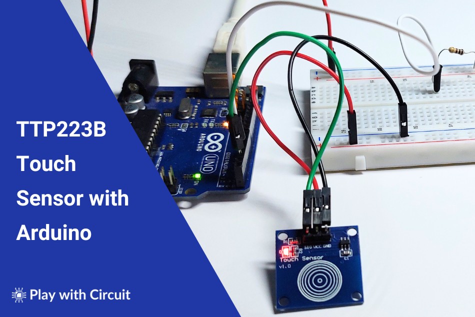
Capacitive touch sensors have become popular in various electronic projects due to their compact size, low power consumption, and versatility. The TTP223B capacitive touch sensor switch is a widely used module that can be easily interfaced with Arduino. It provides a convenient and efficient way to add touch-sensitive capabilities to your DIY Electronic projects.
In this tutorial, we will explore how to interface the TTP223B capacitive touch sensor switch with an Arduino Uno board. We will cover the necessary components, pin description, wiring connections, and Arduino code.
What is TTP223B Capacitive Touch Sensor?
The TTP223B is a 1-channel capacitive type Touch Sensor Module that is based on a touch-sensing IC TTP223-BA6. It consumes very low power and the operating voltage is between 2.0V to 5.5V. It provides a digital output signal, usually in the form of a logic HIGH or LOW, indicating the presence or absence of touch. An LED is present on the module that gives a visual indication of when the sensor is triggered.
Features of TTP223B Touch Sensor
- Low power consumption
- Four M2 screws positioning holes for easy installation
- Power supply from 2.0V to 5.5V DC
- Operating current at low power mode i.e., VDD = 3V is typically 1.5uA and max 3.0uA
- Can replace the traditional touch of a button
- Sensitivity can be adjusted by the external capacitor (0~50pF)
- Stable touching detection of the human body for replacing traditional direct switch key
- Provides direct mode or toggle mode by pad option (TOG pin), Q pin is the CMOS output
- All output modes can be selected active HIGH or active LOW by pad option (AHLB pin)
- Auto calibration for lifetime
Working of TTP223B Capacitive Touch Sensor
The TTP223B operates based on the principle of capacitive sensing. Every object, including our bodies, has some capacitance. When a conductive object, like a finger, approaches or touches the surface of the sensor, it detects changes in capacitance.
The sensor consists of capacitive sensing electrodes, which are connected to the sensing input pins of the sensor. When a finger approaches or touches the surface of the sensor, it changes the capacitance of the system. This change is detected by the oscillator circuit, then the oscillator circuit generates a digital output signal.
A control logic circuit then processes the signals from the oscillator circuit and determines touch events. An output mode & driver circuit then responds to touch events by toggling the state of its output pin, indicating the presence or absence of touch.
This complete processing and controlling is taken care by TTP223-BA6 IC present on the Touch Sensor.
TTP223-BA6 Pinout
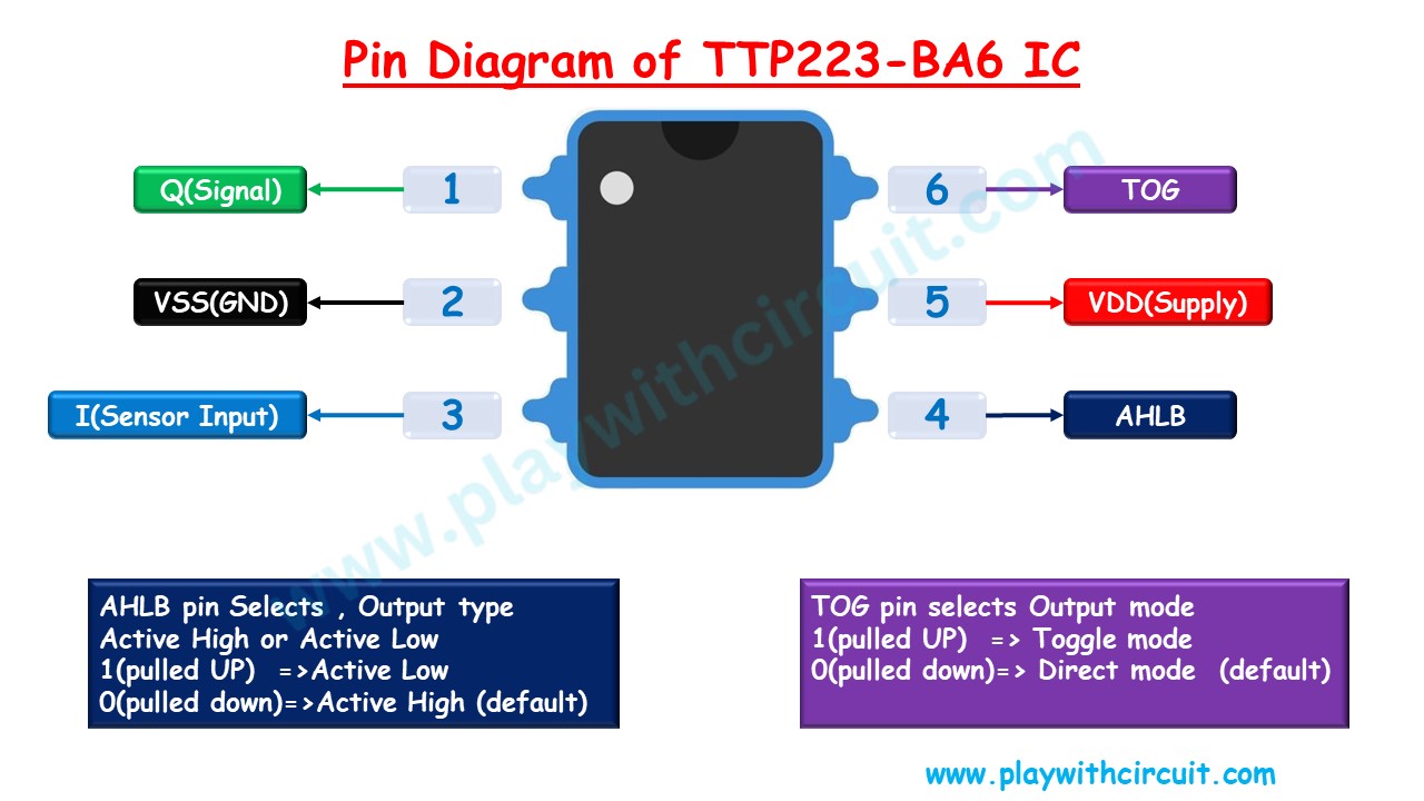
Signal(Q) This pin is the output pin of the IC.
VSS(GND) This pin should be connected to Ground.
Sensor Input(I) This pin senses the capacitance of the system. This is the input pin of the IC.
AHLB This pin is the output state selection pin. When this pin is LOW the output will always be Active HIGH. When this Pin is Pulled HIGH the output pin becomes Active LOW.
VDD(Supply) This pin is connected to the supply pin of the sensor. Supply can range from 2.0V to 5.5V DC.
TOG This pin is the output mode selection pin. When this pin is LOW, the output mode is direct. When this pin is Pulled HIGH the output mode is Toggle Mode.
To know more download the datasheets of TTP223-BA6 IC.
Toggle Mode of Operation
In toggle mode sensor toggles its output state each time it detects a touch. In this mode, the sensor behaves as a flip-flop, changing its output state when touch is detected. For example, if the initial state is LOW, the first touch will toggle it to HIGH. Subsequently, when the next touch is detected the output toggles from HIGH to LOW.
Operation Modes of TTP223-BA6 IC
There are four operation modes based on the pin configuration of the AHLB and TOG pin of TTP223-BA6 IC.
| TOG | AHLB | Operation Mode |
|---|---|---|
| LOW | LOW | Direct Mode and Output is Active HIGH |
| LOW | HIGH | Direct Mode and Output is Active LOW |
| HIGH | LOW | Toggle Mode and Power On state is LOW. |
| HIGH | HIGH | Toggle Mode and Power On state is HIGH. |
TTP223B Touch Sensor Pinout
Here is the pinout of the TTP223B sensor module:
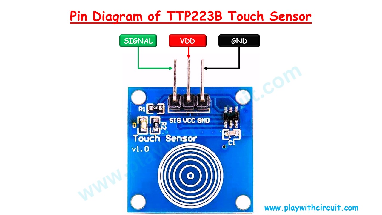
VDD This pin is used to supply power to the sensor module. It is typically connected to a 2.0V or 5V power source.
Signal This pin is the digital output of the sensor. It provides a signal indicating the presence or absence of a touch event. When a touch is detected, this pin goes HIGH (typically to the supply voltage), and when no touch is detected, it remains LOW (typically at ground).
(GND) This pin is connected to the ground of the power supply to complete the circuit.
Hardware Overview of TTP223B Capacitive Touch Sensor
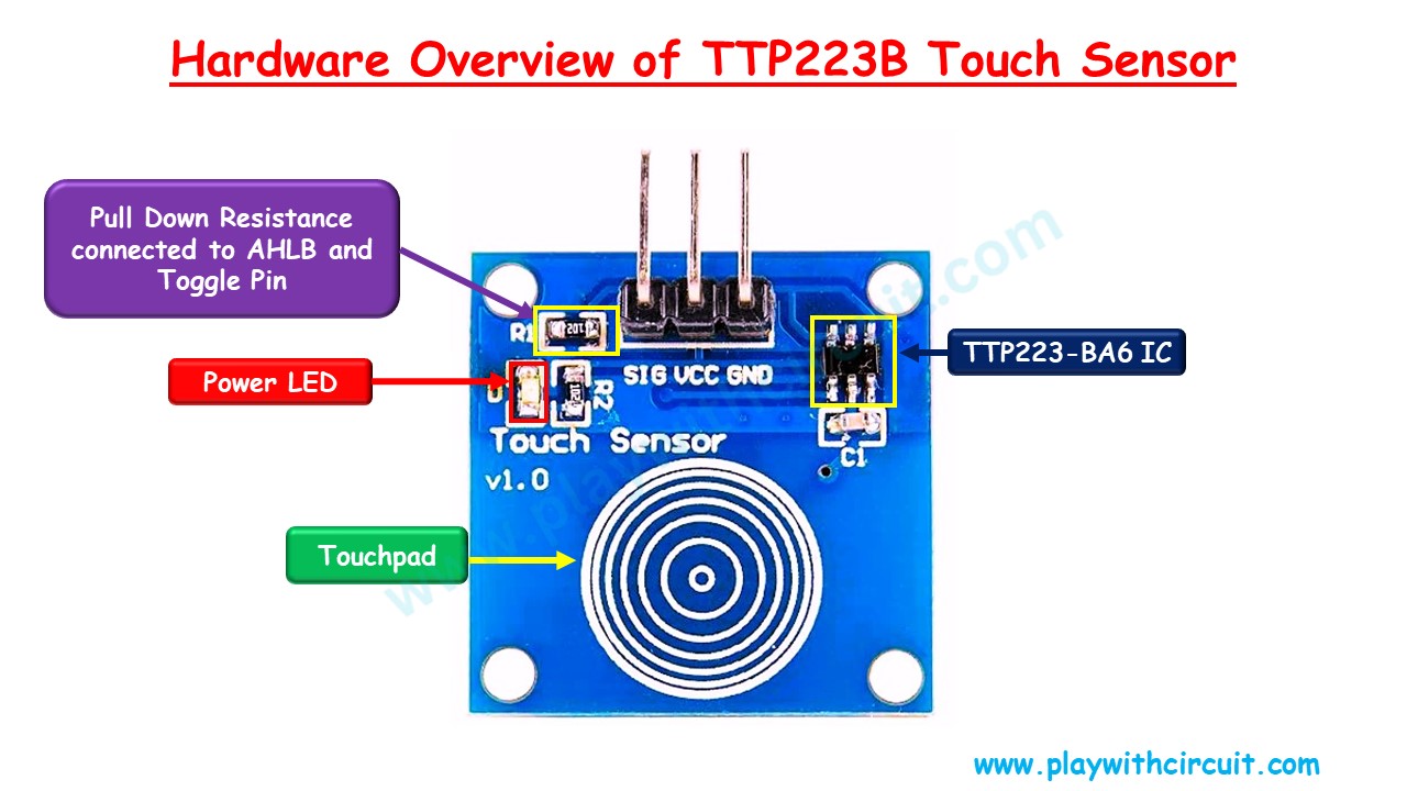
The touch sensor consists of a TTP223-BA6 IC which senses the change in capacitance when touch is detected at the concentric circles present on the sensor. The output pin of the IC changes the state which is connected to the SIG (signal) pin of the Sensor.
As soon as the power is connected at VCC pin and ground is connected at the GND pin, the Red Power LED turns ON.
Internal Circuit Diagram of TTP223B Touch Sensor
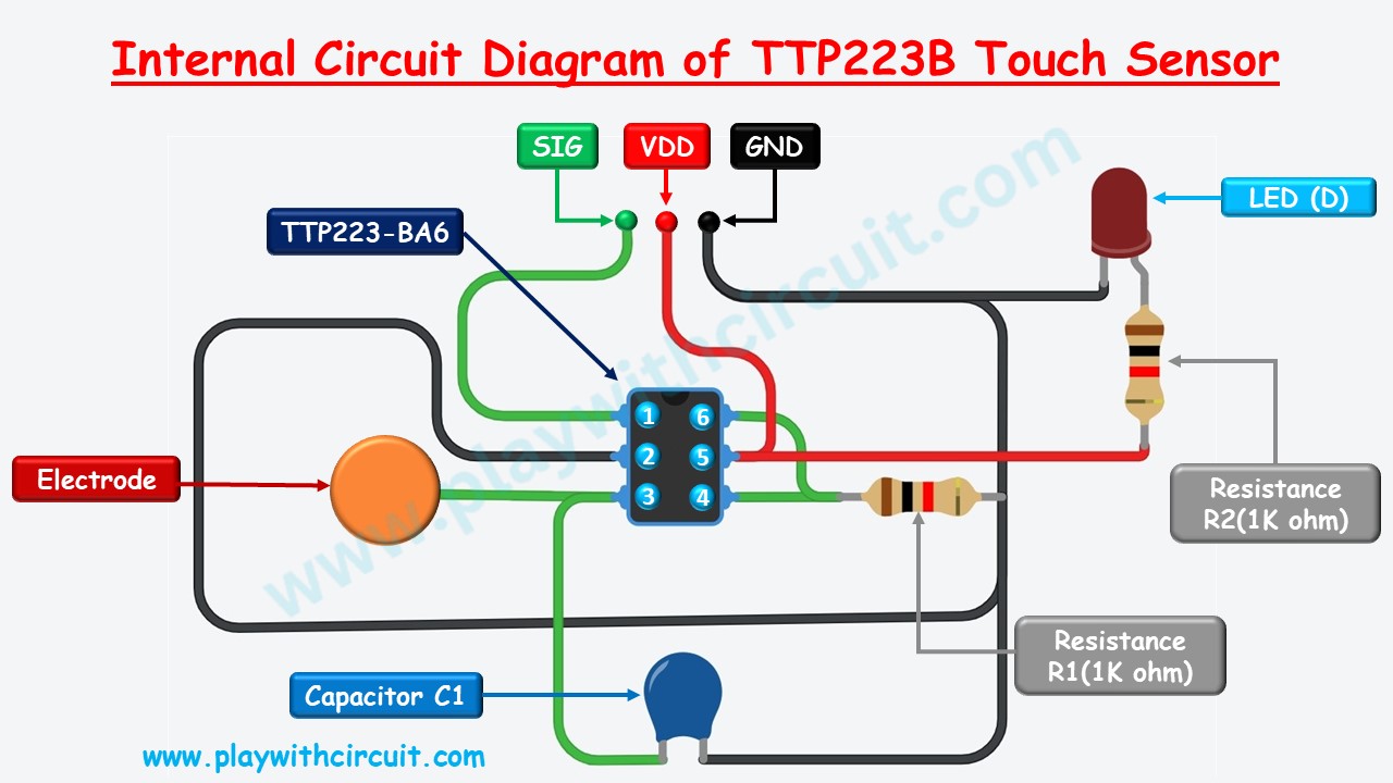
In TTP223B touch Sensor V1.0, the toggle pin (pin 6), and the AHLB pin (pin 4) are pulled to the ground using the 1 kΩ resistance. It means the touch sensor works in direct mode and the output signal is Active HIGH i.e., as soon as the touch is detected it changes its state from LOW to HIGH and remains in this state as long as touch is detected by the sensor.
Pin 1 of the IC is connected to the Signal pin.
Pin 2 of the IC is connected to the Ground.
Pin 3 of the IC is connected to the Electrode and parallelly it is connected to capacitor C1 which is connected to Ground at the other end.
Pin 4 and Pin 6 of the IC are pulled to the Ground, via 1 KΩ resistance R1.
Pin 5 is connected to the Supply pin VDD of the sensor.
An LED (D) is also present which turns ON when the power supply is given to the circuit. It is connected to the supply pin along with 1 KΩ resistance R2 in series.
Interfacing TTP223B Touch Sensor with Arduino
Let us interface TTP223B touch sensor with Arduino UNO.
Hardware Requirement
| Component Name | Quantity | Remarks | Where to Buy |
|---|---|---|---|
| Arduino UNO | 1 | Revision R3 | Amazon.com |
| Touch Sensor | 1 | TTP223B V1.0 | Amazon.com |
| LED | 1 | Red, 5mm diameter | Amazon.com |
| Resistance | 1 | 100 ohms | Amazon.com |
| Breadboard | 1 | Small size | Amazon.com |
| Connection wires | 5 | For circuit connections. | Amazon.com |
Software Requirement
Arduino IDE, Version 2.1.1 or above installed on your PC
Circuit Diagram for Interfacing Touch Sensor with Arduino
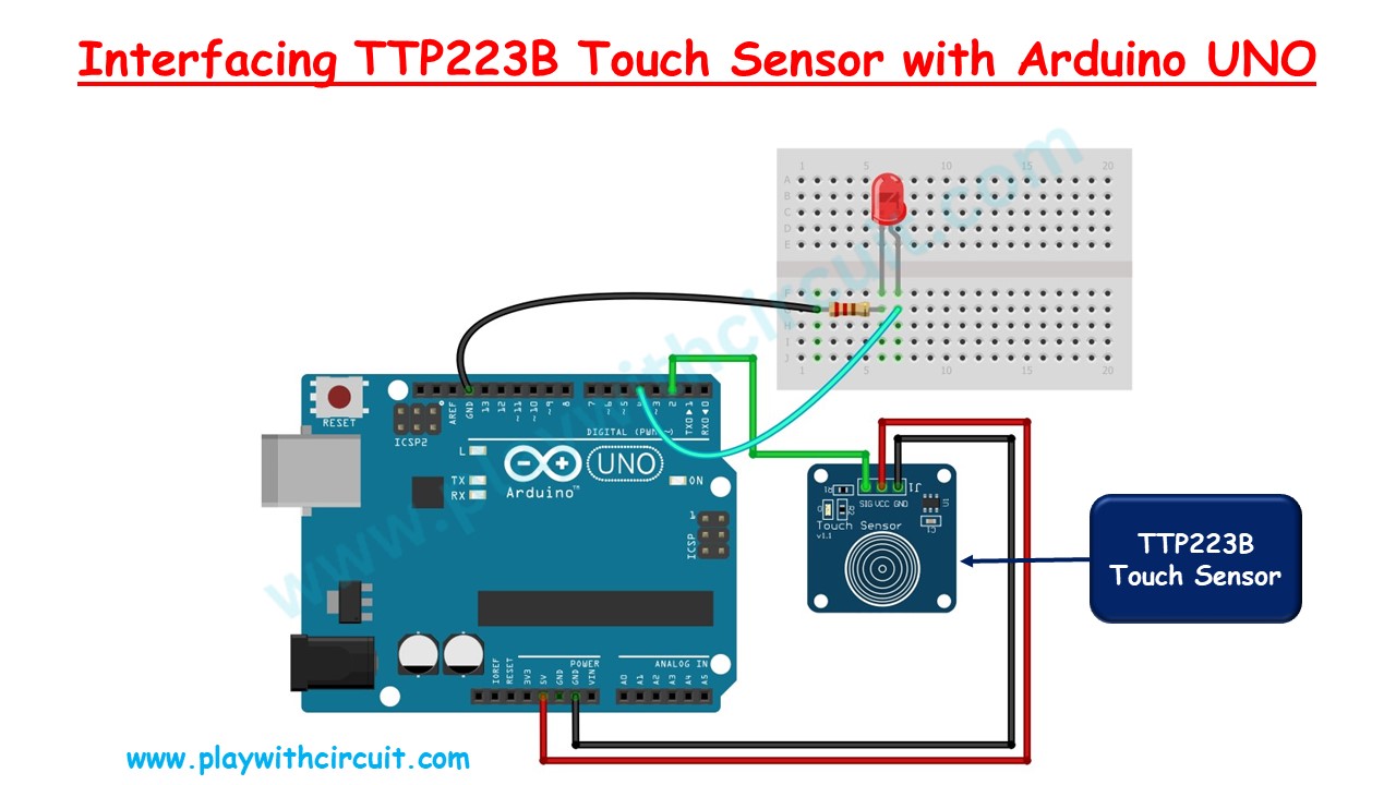
In the above wiring diagram, we can see a TTP223B touch sensor is connected with an Arduino UNO.
The power for the Touch Sensor is provided by Arduino 5V and GND pins. The Signal Output of the touch sensor is connected to the digital input pin 2 of the Arduino.
The Red LED is connected at pin 4 via 100 ohm resistance. When the Touch is detected, LED turns ON and Touch Detected is displayed on the Serial monitor window of Arduino IDE.
Code for interfacing Touch Sensor with Arduino
/*
Interfacing TTP223B Touch Sensor with Arduino
by www.PlaywithCircuit.com
*/
// Define pin numbers
const int touchPin = 2;  // Define the pin number for touch sensor
const int ledPin = 4;    // Define the pin number for LED

void setup() {
  // Initialize serial communication at 9600 baud
  Serial.begin(9600);

  // Set pin modes
  pinMode(touchPin, INPUT);  // Set touchPin as input
  pinMode(ledPin, OUTPUT);   // Set ledPin as output
}

void loop() {
  // Read the state of the touch sensor
  int touchState = digitalRead(touchPin);

  // Check if touch is detected
  if (touchState == HIGH) {
    // Turn on LED
    digitalWrite(ledPin, HIGH);

    // Print touch detected message
    Serial.println("Touch detected!");
    // Staty in the below loop as long as touch is detected.
    while (digitalRead(touchPin) == HIGH);
  } else {
    // Turn off LED
    digitalWrite(ledPin, LOW);
  }
}
Output
Code Explanation
Initially two constants are defined for the touch detection pin and the output pin using the below lines of code.
// Define pin numbers
const int touchPin = 2;  // Define the pin number for touch sensor
const int ledPin = 4;    // Define the pin number for LED
In the setup() function the Serial Output is initialized and pin mode is set for the touchPin and ledPin pin.
void setup() {
  // Initialize serial communication at 9600 baud
  Serial.begin(9600);

  // Set pin modes
  pinMode(touchPin, INPUT);  // Set touchPin as input
  pinMode(ledPin, OUTPUT);   // Set ledPin as output
}
In the loop() function the touchPin is checked if it is HIGH. As soon as it turns HIGH, the LED is turned ON, and “Touch Detected” is printed on the Serial Monitor Window. A while() loop is added after serial print to make sure printing on the serial monitor is done once for one touch event. This functionality is realized using below code lines.
void loop() {
  // Read the state of the touch sensor
  int touchState = digitalRead(touchPin);

  // Check if touch is detected
  if (touchState == HIGH) {
    // Turn on LED
    digitalWrite(ledPin, HIGH);

    // Print touch detected message
    Serial.println("Touch detected!");
    while (digitalRead(touchPin) == HIGH);
  } else {
    // Turn off LED
    digitalWrite(ledPin, LOW);
  }
}
