
Serial communication is essential when working with Arduino boards. It is a method for exchanging data between the Arduino board and other devices such as sensors, displays, or computers. Arduino boards typically have multiple serial communication ports, but Arduino UNO has only one serial com port.
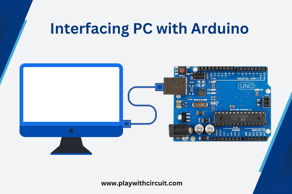
Interfacing a PC with an Arduino Uno using the serial port involves establishing a communication link between the two devices through a USB connection. With real-time communication between the two devices, the link between the PC and Arduino allows programs (sketches) to be sent to the Arduino. The process of effectively connecting an Arduino board to a PC will be covered in this tutorial.
One effective technique to transfer data between a personal computer/Laptop and Arduino is by using a serial connection. In serial communication, characters are packed inside a UART packet which is sent over the serial lines at a certain baud rate which is the same for PC as well as for Arduino. Here PC acts as a slave and sends data to its Master, the Arduino UNO board.
Serial UART communication with a PC requires a minimum of three lines Rx, Tx, and Gnd pin at Arduino’s Side and a USB port at the PC side.
Interfacing PC with Arduino Uno
Let’s understand how to interface PC with Arduino UNO
Hardware and Software Requirements
Hardware
- Arduino UNO
- USB Cable
- Computer with USB port
Software
- Arduino IDE installed on your PC
💡Must Read
Getting Started with Arduino
This article will give you an overview of the Arduino board and how to download and install the Arduino IDE Software.
Interfacing Arduino UNO with PC
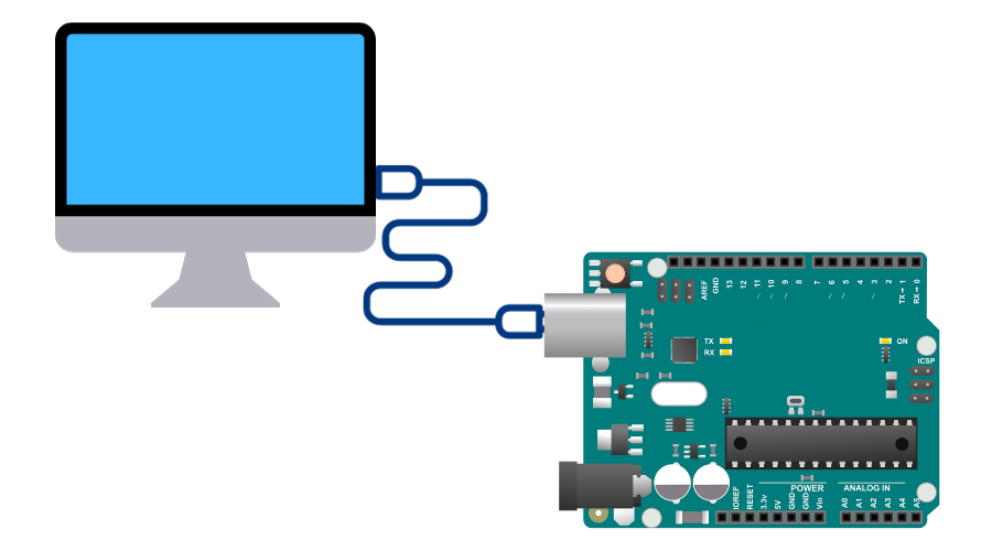
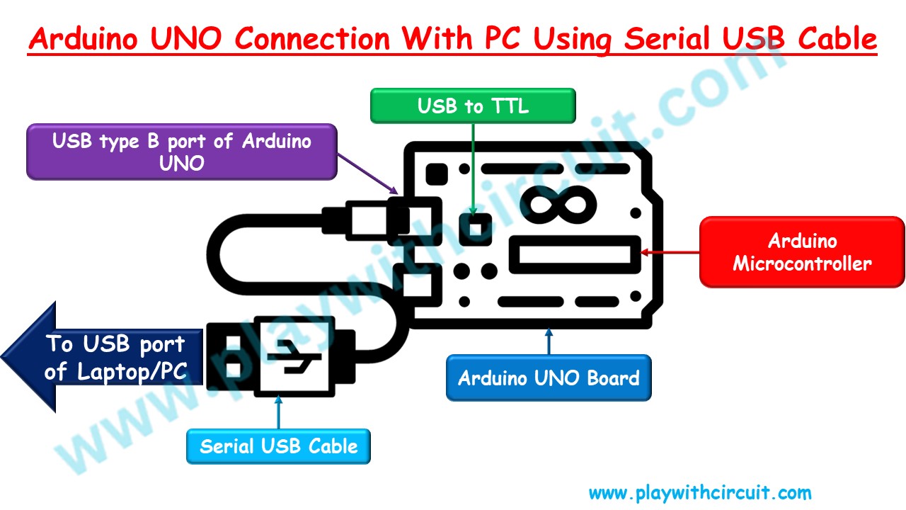
In the above wiring diagram, we can see an Arduino UNO board is connected to the PC via a serial USB cable which is connected to the USB port of the PC.
The Rx and Tx pin of the Arduino Uno is connected to the Tx and Rx of the USB to TTL (it works both ways) converter which converts UART protocol data into USB protocol data. The Serial cable transfers this USB protocol data to the PC USB port.
In some Arduino boards, USB to TTL is an ATMEGA controller and in some boards, it could be CH340 IC.
When IDE is installed on the PC then drivers of this CH340 chip also install with the IDE hence PC can detect the Arduino as a COM port.
Also, the Arduino codes are being written into the Arduino main controller, ATmega328p microcontroller through this connection.
Hence it is advisable to remove any connection with the Tx and Rx pin of the Arduino UNO board while the Arduino is being programmed via its COM port using PC.
Hence this connection serves two purposes:
- First is to program the board.
- Second is to communicate with the PC when the Serial UART port is activated in the code for communication.
Coding Examples
In the below example, we will write different programs to receive data from the PC using the Serial UART Rx pin and write the same data over the Tx pin.
Code 1
char serialInput;

void setup() {
  //Initialize serial and wait for port to open:
  Serial.begin(9600);
  while (!Serial) {
    ;  // wait for serial port to connect. Needed for native USB
  }
}
void printCRLF() {
  Serial.write(13);
  Serial.write(10);
}
void loop() {
  // put your main code here, to run repeatedly:
  printCRLF();
  Serial.print("Enter Something :");
  while (Serial.available() == 0);
  printCRLF();
  Serial.print("You Entered : ");
  do {
    serialInput = Serial.read();
    Serial.print(serialInput);
  } while (Serial.available() != 0);
}
Output:
Code Explanation
In this code first, we check if data is available using Serial.available() function it will wait in the infinite loop function. As soon as data is available it is read using the Serial.read() function and sent to the UART using Serial.print() function in do { } while(); loop as long as data is available.
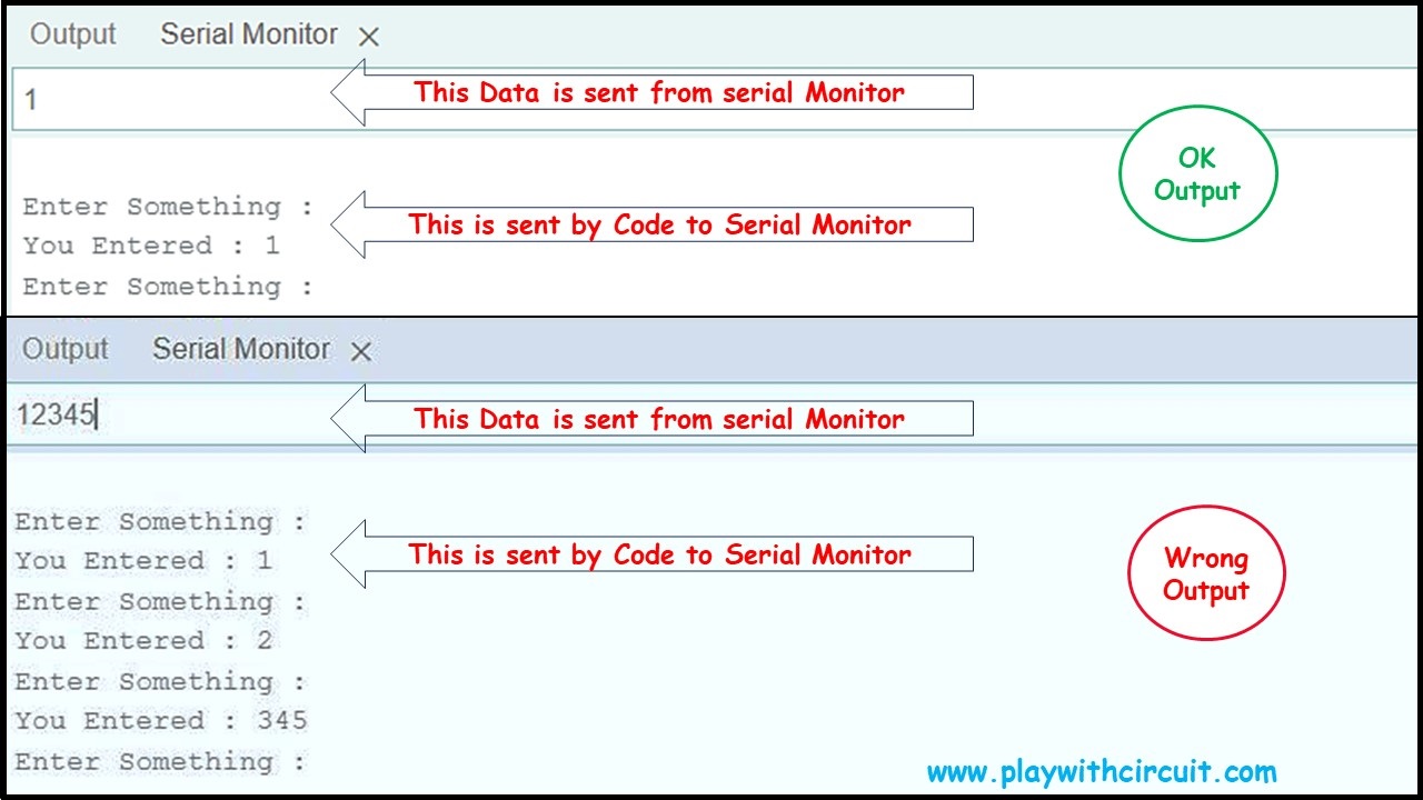
When we enter single-character data the program runs correctly. In the above example when ‘1’ is entered then ‘Enter Key’ is pressed in the Serial Monitor window of Arduino IDE. Then the output is OK.
But when we enter multiple character data like “12345” we expect that “12345” is printed on the UART window but the output is not as per expectations. Hence to get the expected output, another code is written to resolve this problem.
Code 2
char serialInput;

void setup() {
  //Initialize serial and wait for port to open:
  Serial.begin(9600);
  while (!Serial) {
    ;  // wait for serial port to connect. Needed for native USB
  }
}
void printCRLF(){
  Serial.write(13);
  Serial.write(10);
}
void loop() {
  // put your main code here, to run repeatedly:
  printCRLF();
  Serial.print("Enter Something :");
  while (Serial.available() == 0);
  printCRLF();
  Serial.print("You Entered : ");
  do {
    serialInput = Serial.read();
    Serial.print(serialInput);
    delay(10);
  } while (Serial.available() != 0);
}
Output:
Code Explanation
This code is the same as code 1 except, there is a delay of 10ms present in the do { } while(); loop. This code enables the Arduino to capture more bytes.
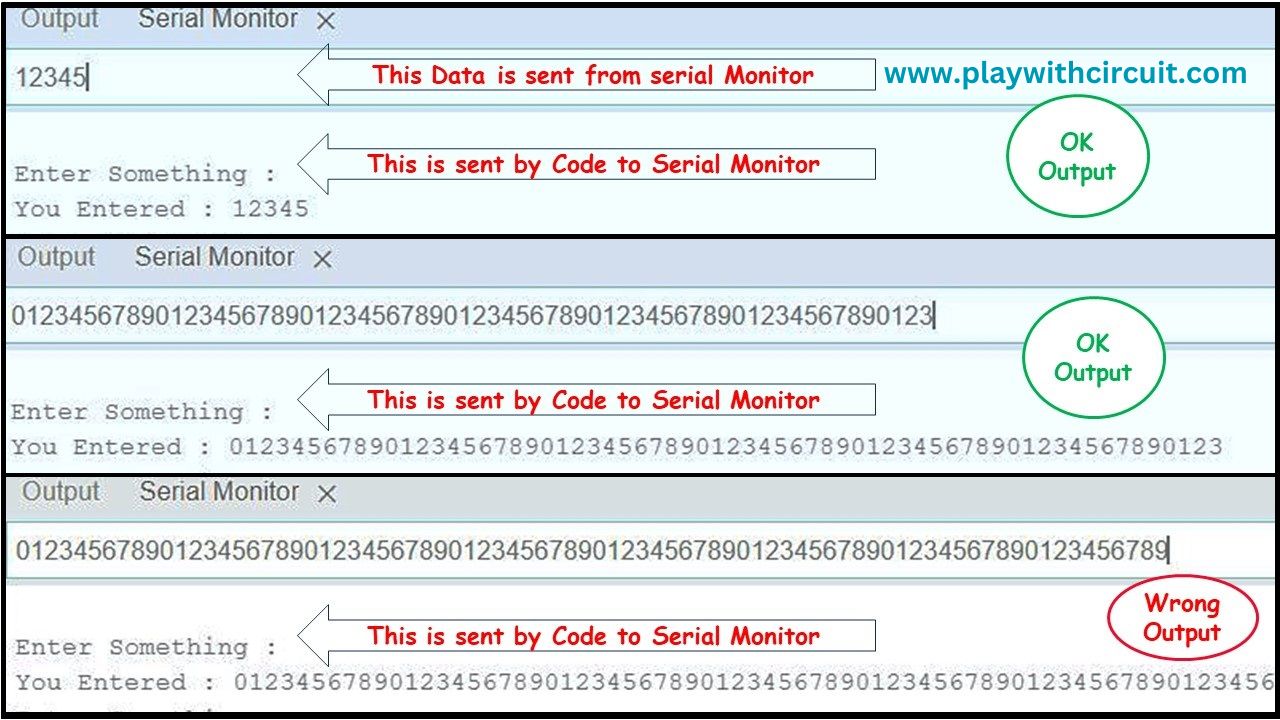
This change has led to a big improvement in the output. In the first picture, the input is “12345”. It’s getting printed correctly.
In the second picture, the input is “0123456789012345678901234567890123456789012345678901234567890123”. It is 64-byte long string; it’s getting printed correctly.
In the third pic, the input is “01234567890123456789012345678901234567890123456789012345678901234567890123456789”. It is an 80-byte long string. The string printed on the Serial Terminal is “012345678901234567890123456789012345678901234567890123456789012345678908”
It’s 72 bytes of data and the last two characters are wrong. It means only 70 bytes of data can be printed without any error. This has to do with something related to the Serial Rx buffer of the UART.
In Atmega328p the microcontroller of the Arduino UNO the hardware Rx buffer is of 64 bytes long. There is one more software buffer which is 64 bytes long and is implemented by this inbuilt serial library that we are using.
But we can get 70 bytes because as soon as Arduino receives data, it is also getting read, which also clears some space in the input buffer hence we can successfully receive and transmit 70 bytes of data without any error.
The limitations of this code will be removed in another coding example.
Code 3
char serialInputArray[1000];
int i = 0;
void setup() {
  //Initialize serial and wait for port to open:
  Serial.begin(9600);
  while (!Serial) {
    ;  // wait for serial port to connect. Needed for native USB
  }
}
void printCRLF() {
  Serial.write(13);
  Serial.write(10);
}
void loop() {
  // put your main code here, to run repeatedly:
  printCRLF();
  i=0;
  Serial.print("Enter Something :");
  while (Serial.available() == 0);
  do {
    Serial.readBytesUntil('#',serialInputArray,1000);
  } while (Serial.available() != 0);
  printCRLF();
  Serial.print("You Entered : ");
  Serial.print(serialInputArray);
  memset(serialInputArray,0x00,sizeof(serialInputArray));
}
Code Explanation
This code enables us to receive up to 1000 bytes of data from the Serial UART Rx input line.
In this code, we are using the function Serial.readBytesUntil(), to receive the data in serialInputArray[1000] which is 1000 bytes long array, until we get the end character which is ‘#’, in our code.
In the example if the input string is
“012345678901234567890123456789012345678901234567890123456789012345678901234567890123456789012345678901234567890123456789012345678901234567890123456789012345678901234567890123456789012345678901234567890123456789012345678901234567890123456789012345678901234567890123456789012345678901234567890123456789012345678901234567890123456789012345678901234567890123456789012345678901234567890123456789012345678901234567890123456789012345678901234567890123456789012345678901234567890123456789012345678901234567890123456789012345678901234567890123456789012345678901234567890123456789012345678901234567890123456789012345678901234567890123456789012345678901234567890123456789012345678901234567890123456789012345678901234567890123456789012345678901234567890123456789012345678901234567890123456789012345678901234567890123456789012345678901234567890123456789012345678901234567890123456789012345678901234567890123456789012345678901234567890123456789012345678901234567890123456789012345678901234567890123456789012345678#”
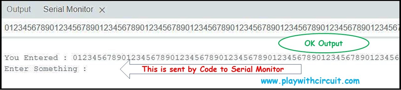
They are a total of 1000 characters including the ‘#’ character. The output on the serial port is
“012345678901234567890123456789012345678901234567890123456789012345678901234567890123456789012345678901234567890123456789012345678901234567890123456789012345678901234567890123456789012345678901234567890123456789012345678901234567890123456789012345678901234567890123456789012345678901234567890123456789012345678901234567890123456789012345678901234567890123456789012345678901234567890123456789012345678901234567890123456789012345678901234567890123456789012345678901234567890123456789012345678901234567890123456789012345678901234567890123456789012345678901234567890123456789012345678901234567890123456789012345678901234567890123456789012345678901234567890123456789012345678901234567890123456789012345678901234567890123456789012345678901234567890123456789012345678901234567890123456789012345678901234567890123456789012345678901234567890123456789012345678901234567890123456789012345678901234567890123456789012345678901234567890123456789012345678901234567890123456789012345678901234567890123456789012345678″
without a ‘#’ character.
Hence, we are successfully able to get 999 characters in one go when our Serial buffer is 1000 bytes long.
The limitation of this code is, that the buffer size is limited by the RAM of the Atmega328p chip which is 2048 bytes only.
The second limitation which is also present in the above codes is we are not able to do other tasks while we are receiving the data on the Serial Rx line.
This limitation can be overcome in the next example.
Code 4
char serialInput;
int dataIndex = 0;
char databuffer[1001] = { 0 };
bool dataRcvd = false;  // whether the string receiving is completed.

void setup() {
  //Initialize serial and wait for port to open:
  Serial.begin(9600);
  while (!Serial) {
    ;  // wait for serial port to connect. Needed for native USB
  }
  printCRLF();
  Serial.print("Enter Data :");
}

void printCRLF() {
  Serial.write(13);
  Serial.write(10);
}
void loop() {
  // put your main code here, to run repeatedly:
  if (dataRcvd == true) {
    printCRLF();
    Serial.print("Data Received :");
    Serial.print(databuffer);
    dataRcvd = false;
    memset(databuffer,0x00,sizeof(databuffer));
  }
}

/*
  SerialEvent occurs whenever new data comes in the hardware serial RX. This
  routine is run between each time loop() runs, so using delay inside loop can
  delay response. Multiple bytes of data may be available.
*/
void serialEvent() {
  while (Serial.available()) {
    // get the new byte:
    serialInput = Serial.read();
    databuffer[dataIndex++] = serialInput;
    // if the incoming character is a line feed character '\n', set a flag so the main loop can
    // do something about it:
    if (serialInput == '\n') {
      dataRcvd = true;
      dataIndex=0;
    }
  }
}
Output:
Code Explanation
One limitation of code 3 has been successfully overcome in code 4 is that this code uses serialEvent() function to get and store the data in the databuffer[1001].
The loop() function is only used to print the received data and while the data is being received and stored in the serialEvent() functionality the loop function can do other important tasks of the application.
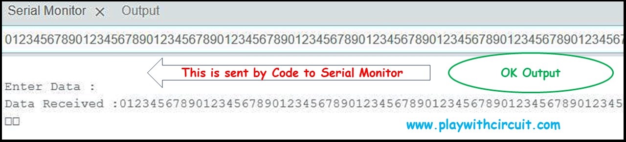
There is one more setting to be done in the serial monitor window of the IDE that every time data is sent a newline character is automatically sent with the actual data. This newline character ‘\n’ is received in the code and is considered as the end character so that the code comes to know that it has to stop searching for data.
The same 1000 character that was sent in the previous code has been sent as input from the Serial Monitor and gets the same output.
