
Boolean operators or logical operators enable you to control the flow of your code. These operators are essential for creating conditional statements, which are used to execute specific blocks of code only when certain conditions are met.
In this tutorial we will discuss about the 3 logical operators in Arduino IDE: OR (||), AND (&&), and NOT (!). We’ll also explore the structure and truth tables of each operator, and how they can be used to solve problems in your Arduino projects.
The following table provides all the logical operators that you will use in Arduino programming.
| Logical Operator | Symbol | Description | Example |
|---|---|---|---|
| And | && | Returns a true value only when both variables are true | a && b |
| Or | || | If any of the two variables is true then the condition becomes true. | a || b |
| Not | ! | Used to reverse the logical state of its operand. If a condition is true then the Logical NOT operator will make it false. | !a |
The OR (||) Operator
The Logic OR (||) operator is used to perform a logical OR operation between two or more conditions.
The easiest way to understand the behaviour of logical operations is with a truth table. This truth table shows how the OR operator works:
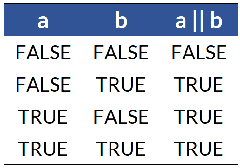
As you can see, the Logical OR (||) operation returns true (or 1 in binary logic) if at least one of the inputs is true. It returns false (or 0 in binary logic) only when both inputs are false.
For example,
int num1 = 7;
int num2 = 12;

void setup() {
  Serial.begin(9600);
  // Check if either num1 is equal to 5 OR num2 is greater than 10
  if (num1 == 5 || num2 > 10) {
    Serial.println("At least one condition is true.");
  } else {
    Serial.println("Both conditions are false.");
  }
}

void loop() {

}
Serial Output:
At least one condition is true.
Explanation of Code:
In the above program, we declare two integer variables, num1 and num2, and initialize them with the values 7 and 12, respectively. In the loop() function, we have a conditional statement using the logical OR operator (||) which checks two conditions:
- Condition 1: num1 == 5 checks if num1 is equal to 5.
- Condition 2: num2 > 10 checks if num2 is greater than 10.
If at least one of these conditions is true, it executes the code inside the if block. If both conditions are false, it executes the code inside the else block. Depending on the results of these conditions, it prints an appropriate message to the Serial Monitor.
The AND Operator (&&)
The AND operator (&&) is used to combine two or more conditions.
Truth Table for the AND Operator (&&):
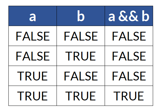
It returns true (or 1 in binary logic) only if all the conditions are true. If at least one condition is false (or 1 in binary logic), it returns false. Let’s illustrate this with a simple example:
int num1 = 5;  // First number
int num2 = 8;  // Second number

void setup() {
  Serial.begin(9600);  // Initialize serial communication
    // Check if both numbers meet a certain condition (e.g., both are even)
  if (num1 % 2 == 0 && num2 % 2 == 0) {
    Serial.println("Both numbers are even.");
  } else {
    Serial.println("At least one number is not even.");
  }
}

void loop() {

}
Serial Output:
At least one number is not even.
Explanation of Code:
In this Arduino code, we have two integer variables, num1 and num2, representing two numbers. Inside the loop() function, we use the AND (&&) operator in the if statement to check if both numbers meet a certain condition.
In this example, we’re checking if both numbers are even.
We use the modulo operator (%) to check if a number is even. If a number modulo 2 equals 0, it’s even. If both num1 and num2 are even, the program will print “Both numbers are even” to the serial monitor. If at least one of the numbers is not even, the program will print “At least one number is not even” to the serial monitor.
The NOT Operator (!)
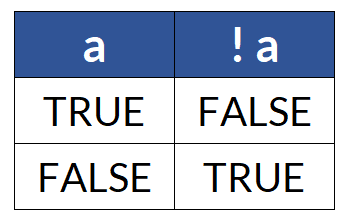
It’s used to reverse the logical state of a value. In simpler terms, if you have a true condition, applying the NOT operator will make it false, and vice versa.
Truth Table for the NOT Operator (!):
Here’s an Arduino code example that demonstrates the use of the NOT operator:
const int buttonPin = 2;  // Pin for the push button
const int ledPin = 13;    // Onboard LED pin

void setup() {
  pinMode(buttonPin, INPUT_PULLUP);  // Enable internal pull-up resistor for the button
  pinMode(ledPin, OUTPUT);           // LED pin as output
  Serial.begin(9600);                // Initialize serial communication
}

void loop() {
  // Read the state of the push button
  bool buttonState = digitalRead(buttonPin);

  // Use the NOT operator to invert the button state
  bool invertedButtonState = !buttonState;

  // Turn on/off the LED based on the inverted button state
  digitalWrite(ledPin, invertedButtonState);

  // Print the original and inverted button states to the serial monitor
  Serial.print("Button State: ");
  Serial.print(buttonState);
  Serial.print(" | Inverted Button State: ");
  Serial.println(invertedButtonState);

  delay(100);  // Delay for a short time to debounce the button
}
Serial Output when Button is not pressed:
Button State: 1 | Inverted Button State: 0
Serial Output when Button is pressed and connected to ground:
Button State: 0 | Inverted Button State: 1
Explanation of Code:
- We define a push button pin (buttonPin) and the onboard LED pin (ledPin).
- In the setup function, we set up the button pin as an input with an internal pull-up resistor and the LED pin as an output. We also initialize serial communication for debugging.
- In the loop function, we read the state of the push button and store it in the buttonState variable.
- We use the NOT operator (!) to invert the buttonState, and the result is stored in the invertedButtonState variable.
- We use the invertedButtonState to control the LED. When the button is pressed (LOW), the LED will turn ON, and when the button is not pressed (HIGH), the LED will turn OFF.
- We also print both the original and inverted button states to the serial monitor to demonstrate the inversion.
Combining Operators for Complex Conditions
In many real-world scenarios, you’ll need to combine multiple conditions to make complex decisions. You can use a combination of AND (&&) and OR (||) operators along with parentheses to control the order of evaluation.
Here’s an Arduino code example that uses a DHT11 or DHT22 humidity and temperature sensor to control a fan. The code will turn on the fan if the temperature exceeds a certain threshold (e.g., 30 degrees Celsius) and the humidity is below a certain threshold (e.g., 60% relative humidity). It will turn off the fan if either of these conditions is not met.
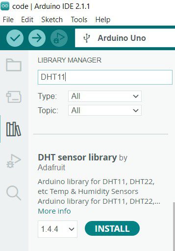
Please make sure you have the DHT library installed in your Arduino IDE to use this code.
If library is not installed then following error occurs:
#include <DHT.h>
compilation terminated.
exit status 1
Compilation error: DHT.h: No such file or directory
Hence go to library manager and install this library.
Code:
#include <DHT.h>

#define DHTPIN 2          // Define the digital pin where the DHT sensor is connected
#define DHTTYPE DHT11     // DHT11 or DHT22, change this according to your sensor

const float tempThreshold = 30.0;  // Temperature threshold in degrees Celsius
const int humidityThreshold = 60; // Humidity threshold in percentage

DHT dht(DHTPIN, DHTTYPE);

void setup() {
  Serial.begin(9600);
  dht.begin();             // Initialize the DHT sensor
}

void loop() {
  // Read temperature and humidity from the DHT sensor
  float temperature = dht.readTemperature();
  float humidity = dht.readHumidity();

  // Check if the sensor reading is valid (non-NaN)
  if (!isnan(temperature) && !isnan(humidity)) {
    Serial.print("Temperature: ");
    Serial.print(temperature);
    Serial.print(" °C, Humidity: ");
    Serial.print(humidity);
    Serial.println("%");

    // Check if the temperature exceeds the threshold and humidity is below the threshold
    if (temperature > tempThreshold && humidity < humidityThreshold) {
      Serial.println("Turn ON AC");
    } else {
      Serial.println("Turn OFF AC.");
    }
  } else {
    Serial.println("Failed to read from DHT sensor!");
  }

  delay(2000); // Delay for 2 seconds before the next reading
}
Output:
Explanation of Code
- We include the DHT library to work with the DHT temperature and humidity sensor.
- We define the digital pin to which the DHT sensor is connected (DHTPIN) and the DHT sensor type (DHTTYPE).
- In the setup function, we initialize serial communication and the DHT sensor.
- In the loop function, we read temperature and humidity from the sensor and check if the readings are valid (not NaN means “Not a Number”)
- If the readings are valid, we compare them to the defined thresholds. If the temperature is higher than the threshold and the humidity is lower than the threshold, then print on Serial “Turn ON AC” else print “Turn OFF AC”.
- Serial communication is used for debugging, and there’s a delay between readings as the sensor doesn’t change values so rapidly even if temperature/humidity changes.


