
Arduino is a great way to start learning and tinkering with electronics. Its simplicity, flexibility and affordability have made it a popular choice to build different DIY electronics projects.
Getting started with Arduino is very simple. This article covers everything you need to know for getting started with Arduino including an overview of the Arduino board, the IDE- programming language and use it to upload your first example sketch.
What is Arduino?
Arduino is an open-source electronics prototyping platform developed for students, hobbyists, programmers and anyone with an interest in electronics. Arduino refers to both a hardware and a software development environment. The hardware consists of a microcontroller board with various input/output pins, connectors, and components. The software, known as the Arduino IDE (Integrated Development Environment), allows users to write, compile, and upload code to the Arduino board.
There are different types of Arduino boards available, each with its own specifications and features. The most commonly used board is the Arduino Uno, which is suitable for a wide variety of projects. Other popular boards include Arduino Mega, Arduino Nano, and Arduino Leonardo. These boards differ in terms of size, number of input/output pins, memory capacity, and processing power. Additionally, Arduino boards can be enhanced with additional shields, which are expansion boards that provide extra functionality such as Wi-Fi connectivity, motor control, or LCD displays.
Arduino Uno Board
When you’re getting started with Arduino, it is recommended to start with the basic board like Arduino Uno. It is a versatile microcontroller board which is easy to use and inexpensive while providing all the basic functionality required for simple electronic projects.
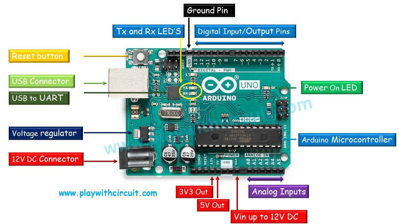
There are several key components of an Arduino Uno board:
Digital Input/Output Pins The Arduino Uno board has 14 digital input/output (I/O) pins labeled from 0 to 13. These 14 pins can be configured as either digital inputs or digital outputs. Out of 14 pins, 6 pins can be used as PWM (Pulse Width Modulation) output pins and 2 can be used as PWM (Pulse Width Modulation) input pins. PWM out pins are 3, 5, 6, 9, 10, and 11 and PWM in pins are 2 and 3.
Analog Input Pins The Arduino Uno board provides 6 analogue input pins labelled from A0 to A5. These pins are useful for reading values from sensors, such as temperature sensors, light sensors, and potentiometers.
Microcontroller This is the main controller IC on which Arduino Code is stored. It is Atmel ATMEGA328P microcontroller. It is the Brain of the Arduino Board. When Arduino board is powered up it executes the instructions stored in its 32KB flash memory.
USB Connector A USB connector allows users to connect it directly to a computer or other devices for programming and communication. It serves multiple purposes. Firstly, it provides a means to power the board during development and testing phases. Secondly, the USB connection allows users to upload code to the board and facilitates serial communication between the Arduino Uno and the computer, allowing data exchange and debugging.
12 V DC Connector The Arduino Uno board can also be powered by using batteries. The board features a DC power jack where users can connect an external power supply within the recommended voltage range(12V to 15V DC). Additionally, with the Vin pin on the Arduino Uno board we can supply power directly to the board by connecting it to an external regulated power source up to 12V, such as a battery.
GND This pin provides ground connection to the external circuit.
Pin 3.3V This pin provides 3.3V output voltage to external circuit/board.
Pin 5V This pin provides 5V output voltage to external circuit/board.
USB to UART converter The serial Tx and Serial Rx pin signals are converted into USB signals by USB to UART converter. This is an Atmel controller ATMEGA 16U2 which is also used to program Arduino microcontroller which is ATMEGA328P
Voltage Regulator It controls the voltage provided to the microcontroller and other onboard components.
Power LED Indicator This LED lights up when the board is plugged in a power source.
Tx/Rx LEDs Transmit and receive data indication LEDs.
Reset Button This button is used to reset Microcontroller present on the Arduino board.
Arduino Microcontroller This is the main controller IC on which Arduino Code is stored. It is Atmel ATMEGA328P microcontroller. It is the brain of the Arduino Board. When Arduino board is powered up, it executes the instructions stored in its 32KB flash memory.
Arduino Uno Board Specifications
| Microcontroller | ATmega328P |
| Operating voltage | 5V |
| Input voltage | 7-12V |
| Flash memory | 32KB |
| SRAM | 2KB |
| On chip EEPROM | 1KB |
| Number of analog inputs | 6 |
| Number of digital I/O | 14 (6 of them Pulse Width Modulation output pins) |
| Clock speed | 16 MHz |
Compatibility and Expandability
One of the key features of the Arduino Uno board is its compatibility with shields, which are add-on boards that expand the capabilities of the Arduino. Shields can provide functionalities such as motor control, display interfaces (LCD, OLED), wireless communication (Wi-Fi, Bluetooth), and more. These shields can be easily stacked on top of the Arduino Uno, allowing users to customise and enhance their projects without the need for complex wiring or soldering.

Basic Components You will need for the Project
Here is the list of the components you will need to get a project up and running:
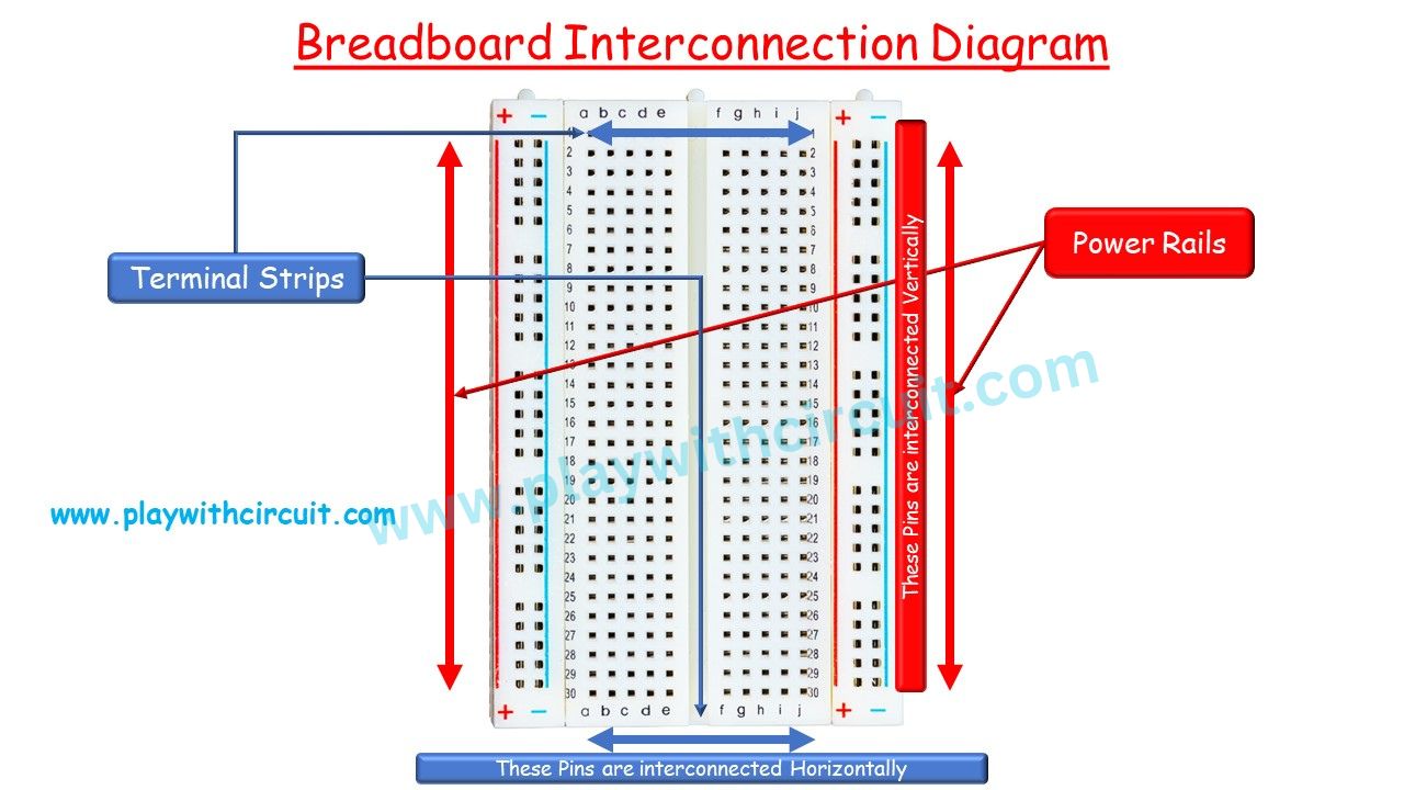
Breadboard
A breadboard is used for prototyping electronic circuits. It is a rectangular board with a grid of holes and metal clips that allow electronic components to be easily connected without the need for soldering. It is typically made of plastic, and the holes are arranged in a pattern of rows and columns.
It consists of two main sections: the terminal strips and the power rails. The terminal strips run horizontally across the breadboard and are used to connect components. Each terminal strip typically contains multiple interconnected holes in a row, and each hole within the row is electrically connected. The power rails, usually located on the sides of the breadboard, provide connections for power supply. These power rails run vertically along the breadboard and are also interconnected across multiple holes.
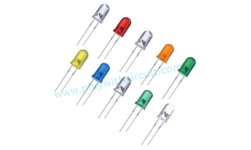
LEDs
LEDs(Light Emitting Diode) are electronic devices that emit light when electric current passes through them. They are often used as visual indicators to display status, for example, they can indicate power on/off, battery status, or signal presence.
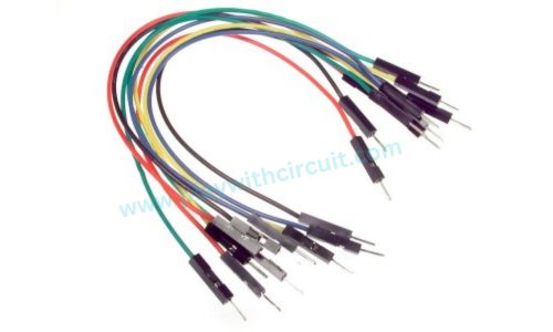
Jumper Wires
Jumper wires allow you to make temporary connections between different electronic components, such as microcontrollers, sensors, actuators, and breadboards. They are flexible wires with connectors on each end, typically with male-to-male, female-to-female, or male-to-female connectors.
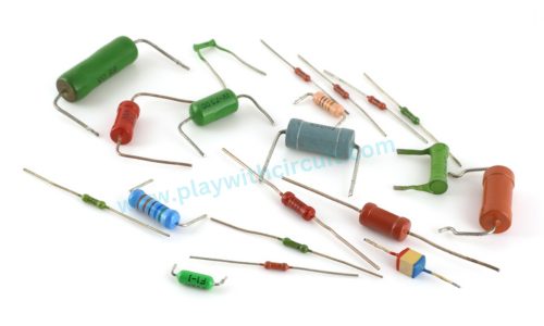
Resistors
Resistors are used to control the flow of current in a circuit, ensuring that components such as LEDs or sensors are not subjected to excessive current that could damage them. Understanding the role and proper selection of resistors is crucial for building safe, reliable, and functional Arduino projects.
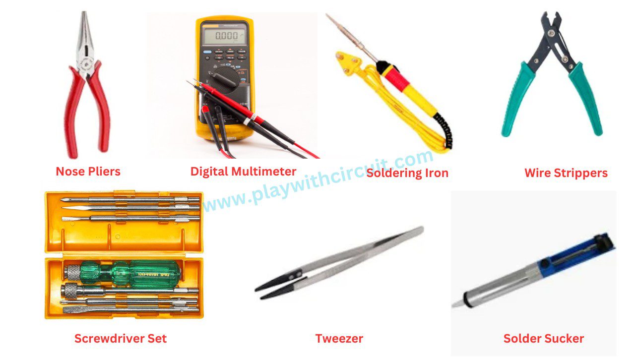
Tools Required
When working on Arduino projects, it is essential to have the necessary tools at hand. These tools will enable you to effectively work with Arduino boards:
- Nose Pliers
- Digital Multimeter
- Soldering Iron
- Wire Strippers
- Screwdriver Set
- Tweezer
- Solder Sucker
The Arduino IDE
The Arduino IDE is a software application used to write, compile, and upload code to the Arduino board. It provides a user-friendly interface for writing Arduino programs using the Arduino programming language, which is based on C/C++ which is very easy to learn.
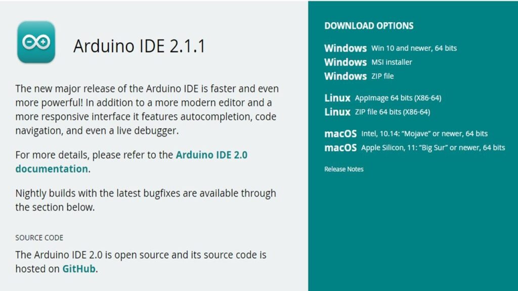
To write code for your Arduino project, download and install the Arduino IDE (Integrated Development Environment) from the official Arduino website. If you have a Windows system, download the Windows installer package and install the IDE on your computer just like any other program. If you don’t have permission to install programs on your computer, download the Windows ZIP file. Extract all the files and then you can open the software by clicking on the arduino.exe file inside the folder.
Linux users can download the file for 32 bit, 64 bit or ARM systems and Mac users can download and install the file for Mac OS X.
After installing open the Arduino IDE which will be like this:
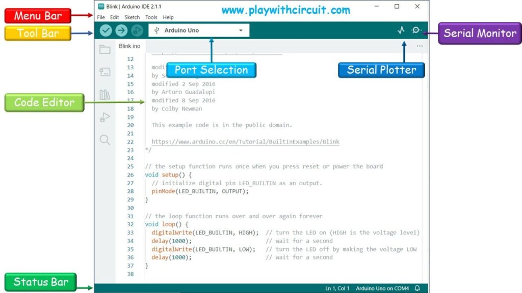
Here are major components of IDE:
Menu Bar The menu bar is located at the top of the Arduino IDE window. It contains various menus, including File, Edit, Sketch, Tools, and Help. These menus provide access to different commands and options for managing your Arduino projects.
Tool Bar The tool bar is located just below the menu bar and contains icons representing frequently used commands. It provides quick access to options such as verifying and uploading sketches, debugging. You can also select the appropriate board type in the toolbar.
Code Editor The code editor is the main workspace in the center of the Arduino IDE window. This is where you write your Arduino sketches (programs). The code editor provides syntax highlighting, auto-indentation, and other helpful features to assist with code writing.
Status Bar The status bar is located at the bottom of the Arduino IDE window. It displays useful information such as the current board and port selection, the status of the compilation and upload process, and any error or warning messages.
Serial Monitor The Serial Monitor is a tool integrated into the Arduino IDE that allows you to communicate with the Arduino board via the serial port. It can be opened from Tool Bar.
Serial Plotter The Serial Plotter is a built-in tool in the Arduino IDE that allows you to graphically represent data sent over the serial port. This tool is particularly useful when working with sensors, analog inputs, or any data that changes over time. It can be opened from Tool Bar.
Port Selection In the “Tools” menu, you can select the serial port to which the Arduino board is connected.
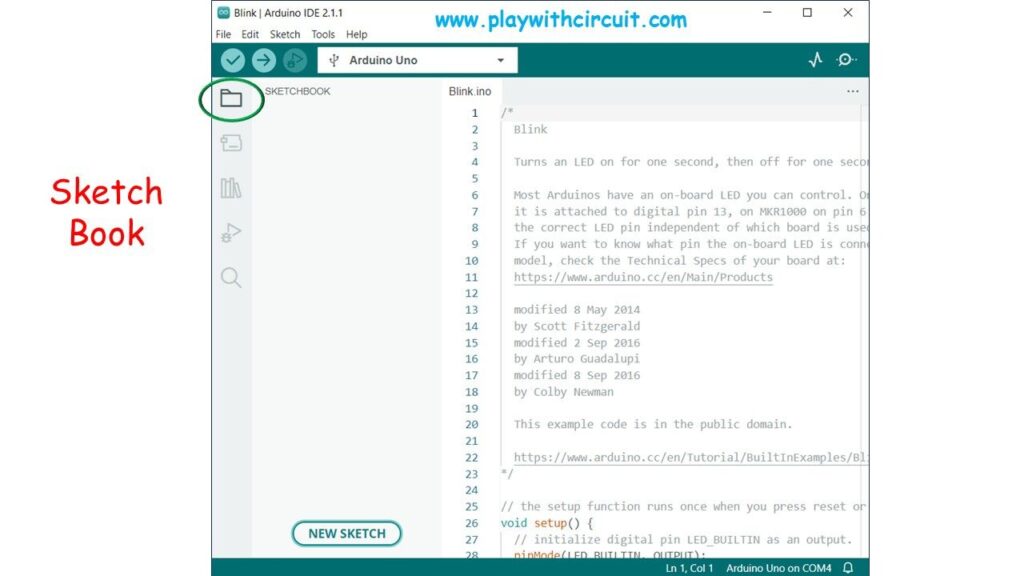
Sketch Book Sketch Book refers to a designated folder on your computer where you can store and organize your Arduino sketches (programs). When you install the Arduino IDE on your computer, it creates a default sketchbook folder where your sketches are saved by default. However, you can choose to use a different location for your sketchbook if you prefer. This can be particularly useful if you want to keep your sketches organized, back them up, or share them with others.
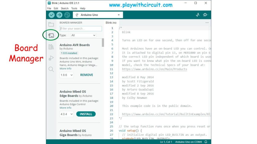
Board ManagerThe Board Manager is used to install different cores on your local computer. A core is written and designed for specific microcontrollers of Arduino boards. Core is essential for using a specific board.
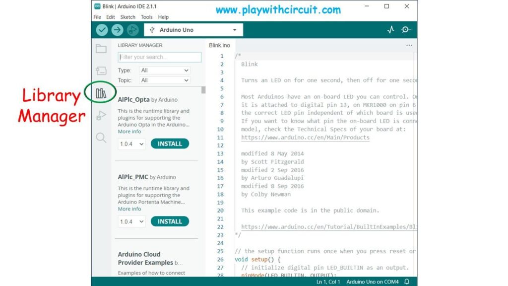
Library ManagerThe Library Manager in Arduino is a tool that simplifies the process of adding external libraries to your Arduino projects. Libraries are collections of pre-written code that can be easily integrated into your Arduino sketches. They provide ready-made functions and classes that you can use to accomplish various tasks without having to write the code from scratch. Using the Library Manager saves you time and effort by allowing you to easily access and integrate external code libraries into your projects.
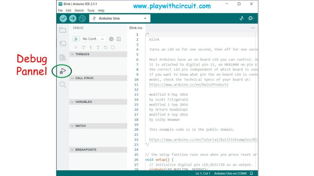
Debug PanelDebug panel allows you to monitor and visualise various aspects of your program’s behaviour, such as sensor readings, variable values, or the flow of program execution. It’s a valuable tool for diagnosing issues and understanding how your code is running.
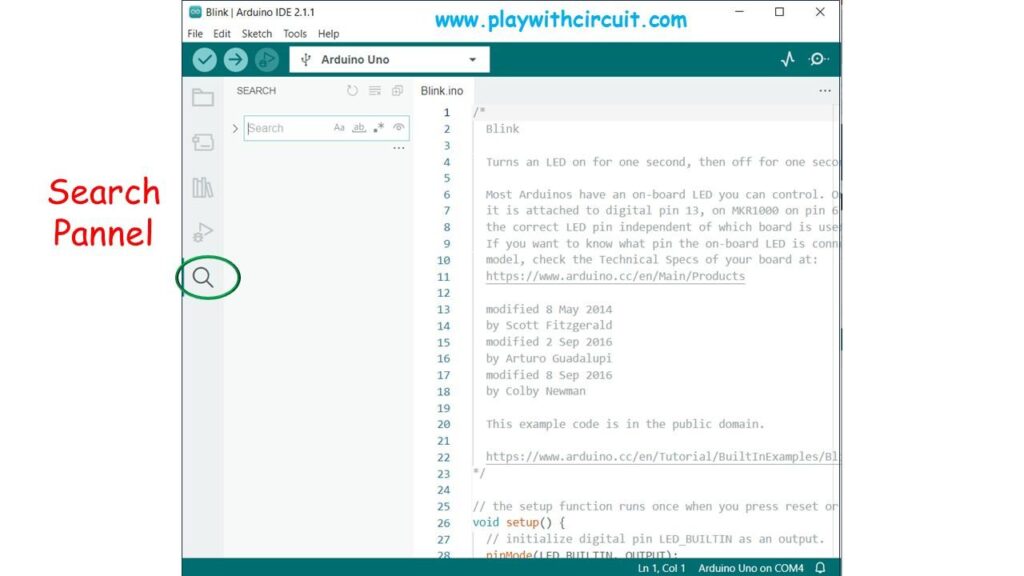
Search PanelSearch panel allows you to search for specific text within your code.
Configuring the Arduino IDE
After the installation of IDE, you need to select the board type from the toolbar. Setting the board type tells the software which microcontroller you are using so it can compile the program accordingly.
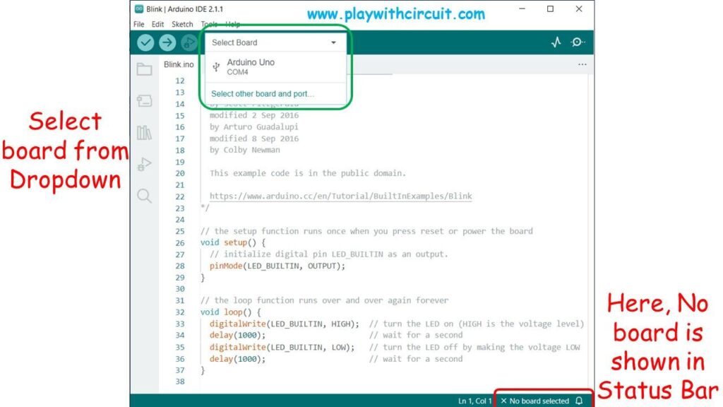
Now we need to select the serial port for sending data to the Arduino. But first the Arduino board needs to be connected to the computer with a USB cable. Once it’s connected, you will see an LED labelled ‘ON’ light up.
Now, Click on Select Board Dropdown List and select the COM port on which Arduino board is connected.
How to Execute the Arduino Code
Now that you have installed and configured the Arduino IDE, you can upload your first sketch in it. Here we will use the “Blink” sample application.
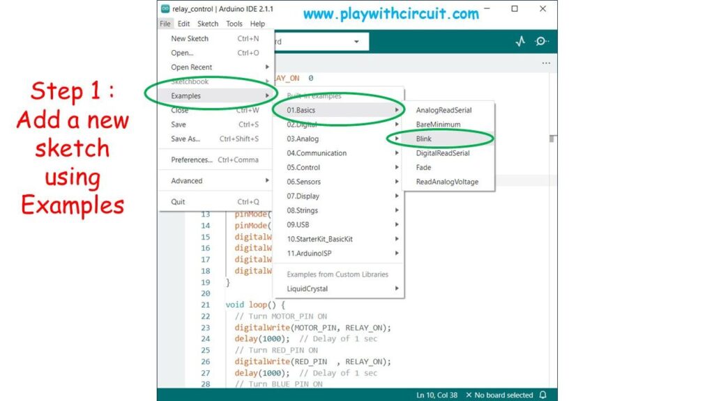
Step 1 Now, open the LED blink example sketch: File > Examples > 1.Basics > Blink. You should see the code for the application open:
Step 2The Blink sketch will appear. Don’t worry if you don’t understand the code, since you will learn about programming Arduino in the next tutorials. For now, just know that this program will make the LED marked “L” on the Arduino board to blink once every second. This LED is right next to the pin marked 13.
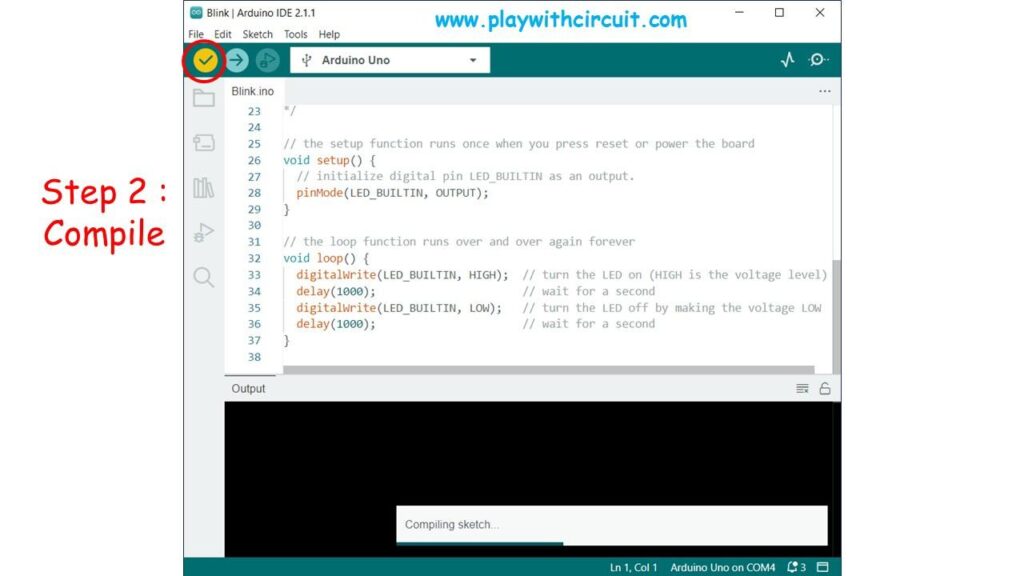
Now once you have code in your Editor. You have to compile it to check for any error. Since it’s a prewritten example code. Hence there will be no error in it. We can also skip this step for this time.
Step 3Finally, click the Upload button on the top left of the toolbar. The IDE will first compile and then upload the sketch to your connected Arduino board.
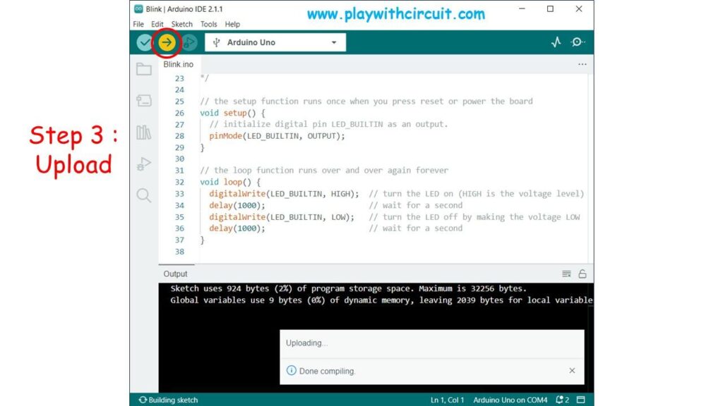
Wait for a few seconds, and you will see the Rx and Tx LEDs on the Arduino flashing. If the upload is successful, the message “Done uploading” will appear in the status bar.
A few seconds after the upload finishes, you should see the onboard LED connected to pin 13 starts to blink. Congratulations! You’ve got your Arduino up and running.
When the upload process finishes, have a look at the onboard LED connected at pin13. It starts blinking once per second. Congrats! You have successfully uploaded your first sketch.
You can see how easy it is. But this is just the start.
In our next tutorial, you’ll learn about how to program Arduino.


