
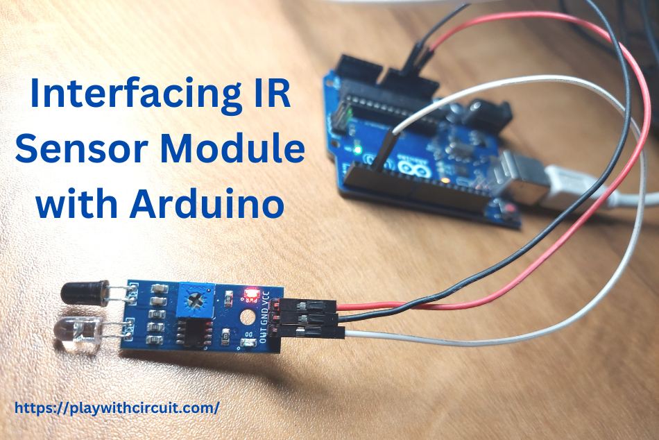
IR sensors are one of the most widely used sensors in robotics and automation projects. Whether it’s a line-following robot, an obstacle-avoiding robot or a product counting system on a conveyor belt, IR sensors helps to detect nearby objects without physical contact. Their low cost, fast response, and simple interfacing make them a popular choice among students, hobbyists, and engineers.
In this tutorial, we’ll understand how an IR sensor module works, explore its hardware and pinout, and learn how to interface it with Arduino to detect the presence of nearby objects.
What is an IR sensor?
Infrared sensor is an electronic device that detects and measures infrared radiation in its surroundings. IR sensors are commonly used to measure the heat of an object and detect the motion. The IR sensor offers several advantages, including low power consumption, a simplistic design, and convenient features.
Technical Specifications
| Distance | 2 ~ 10 cm |
| Operating Voltage | 3.3V to 5V |
| Detection angle | 35 ° |
| Power Supply | 3-5V DC |
| Board size | 3.1 cm * 1.5 cm |
What are the Types of IR Sensor?
IR sensors can be classified into two types: Active Infrared Sensor and Passive Infrared Sensor.
- Active Infrared (AIR) Sensor: AIR sensor includes both the transmitter and the receiver. In most of the applications, the LED is used as a source. These sensors emit infrared radiation and measure the reflected signal. They are often used for object detection, proximity sensing, and edge detection in applications like robotics.
- Passive Infrared (PIR) Sensor: PIR sensor includes only detectors and they don’t have a transmitter. These sensors use an object like a transmitter. They detect changes in infrared radiation emitted by living beings and hot objects. They are commonly used in motion detection systems, such as security alarms and automatic lighting systems.
How HC-SR501 PIR Sensor Works & How to Interface it with Arduino
Explore this tutorial to learn more about PIR Sensor and connecting it with Arduino Uno.
How Does an IR (Infrared) Proximity Sensor Module Work?
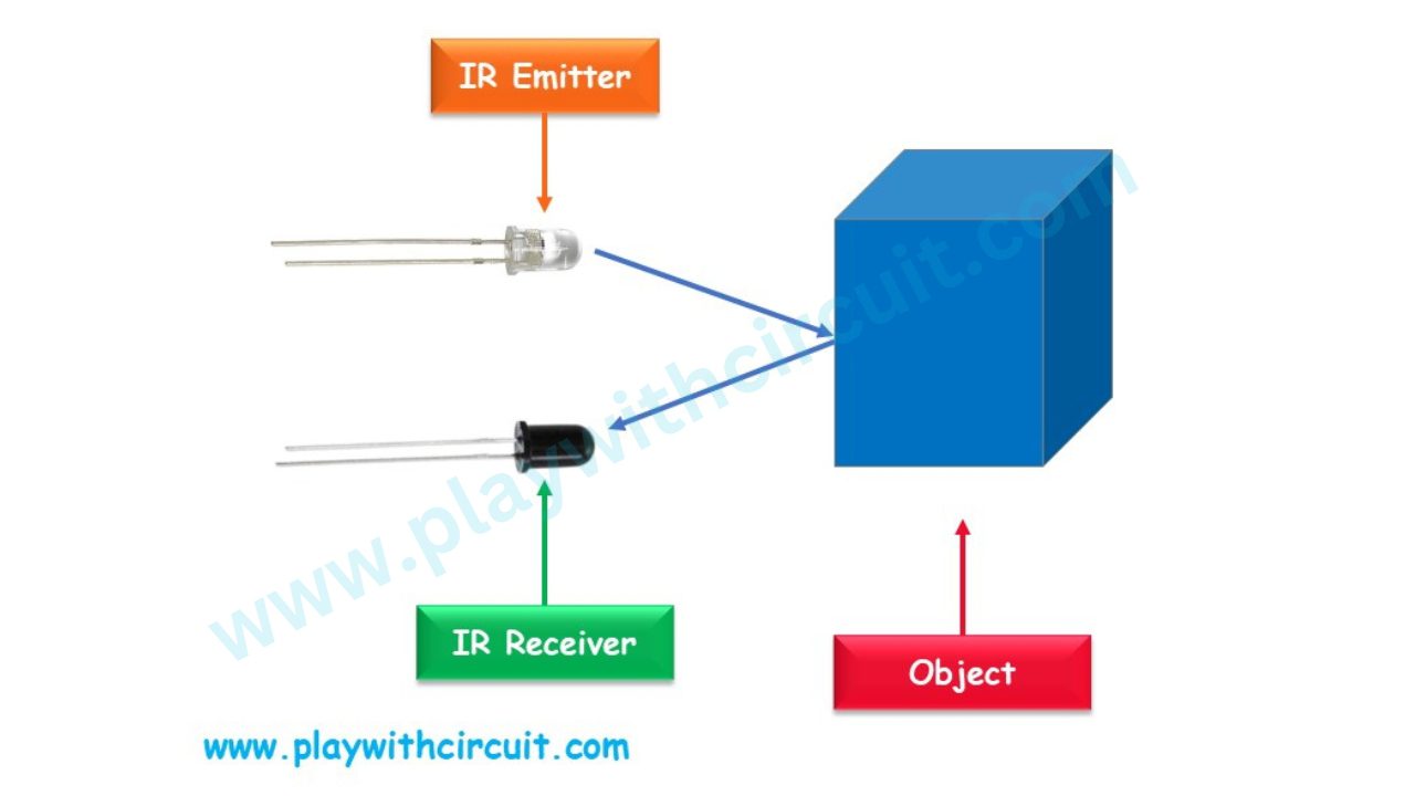
An Infrared Proximity sensor Module consists of two parts namely the transmitter & receiver. In it, IR LED is used as a transmitter and the photodiode is used as a receiver. The infrared photodiode is responsive to the infrared radiation that is produced by IR LED.
When we apply voltage to the IR LED, it emits infrared light. This light hits the object and after that the light gets reflected towards the photodiode sensor. The intensity of the reflected signal depends on the proximity of the object. If the object is closer, signal is strong and if the object is far away, signal is weak.
One exciting feature of this Module is that it consists of two built-in LEDs. One of these LEDs illuminates when power is supplied, while the other LED activates when the circuit is triggered.
IR Proximity Sensor Module Hardware Overview
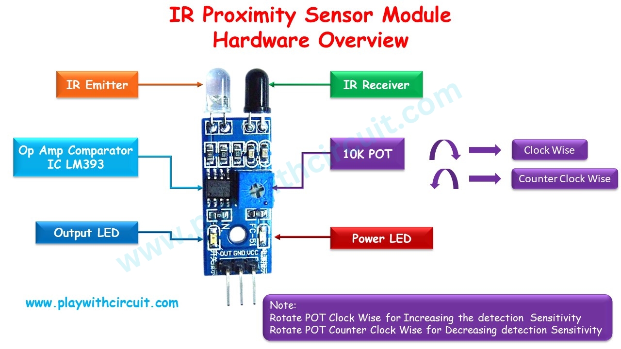
IR Emitter The IR emitter is an infrared light-emitting diode (LED) that emits infrared radiation. It acts as a source of infrared light.
IR Receiver The IR receiver is a component that detects the infrared radiation emitted by the IR emitter. It can be a photodiode or a phototransistor, which converts the received infrared light into an electrical signal.
Comparator Op-amp It is used to compare the voltage at IR receiver with reference voltage. It determines whether object is in close proximity with sensor based on the received signal strength compared to the reference voltage
Trim Pot Adjust Distance The Trim Pot refers to a potentiometer (variable resistor) used for adjusting the distance or sensitivity of the motion sensor module. By adjusting the potentiometer, you can modify the detection range or sensitivity of the module according to your requirements.
Output LED The output or signal LED is an indicator that shows object is Near or Far. When Object is near it glows.
Power LED The power LED is a light-emitting diode (LED) that indicates whether module is receiving power. It is usually connected to the power supply and lights up when the module is properly powered.
IR Sensor Module Pinout
The IR sensor has a 3-pin connector that interfaces it to the microcontrollers.
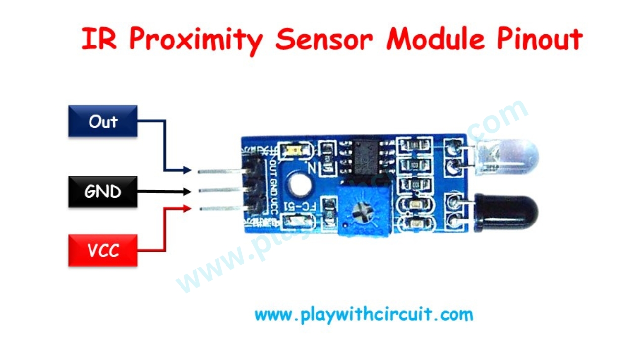
The connections are as follows:
Vcc This pin is used to provide power supply to the sensor. It is connected to the 5V pin on the Arduino.
GND This pin is the ground or reference voltage connection. It is typically connected to the ground of the Arduino.
OUT This pin is the output pin of the IR sensor. It provides digital LOW signal when object is near to sensor and digital HIGH signal when Object is far from sensor.
Circuit Diagram of IR Proximity Sensor Module
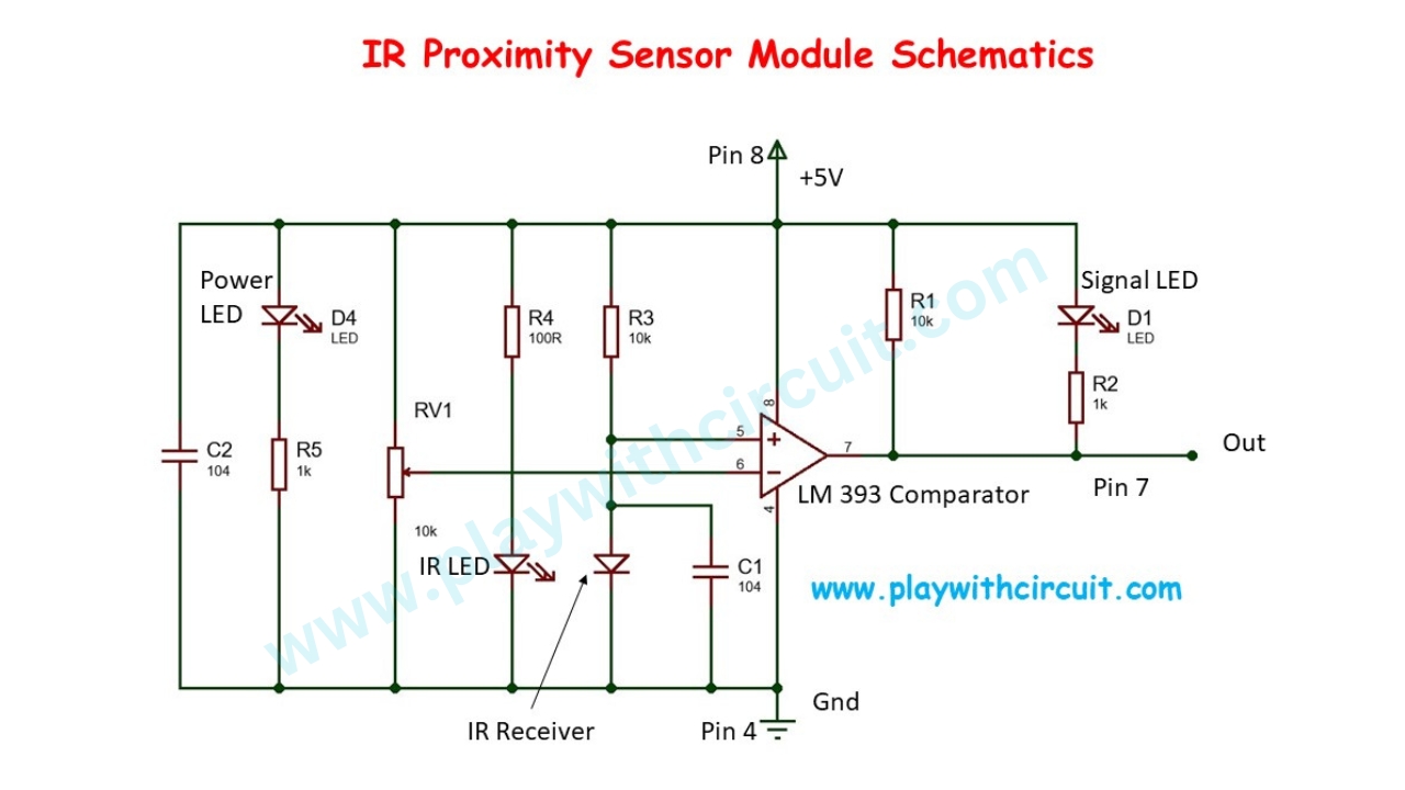
LM393 is a dual comparator IC in our proximity sensor we are using second comparator. The positive input of second comparator is at pin 5 and the negative input at pin 6 and based on the voltage at there two pins output is provided at pin 7 which is the out pin of our IR Sensor.
The basic principle of comparator is that when the voltage at positive input is greater than the voltage at negative input the output is HIGH. Similarly, when the voltage at positive input is less than the voltage at negative input the output is LOW.
What Happens when the Object is Far
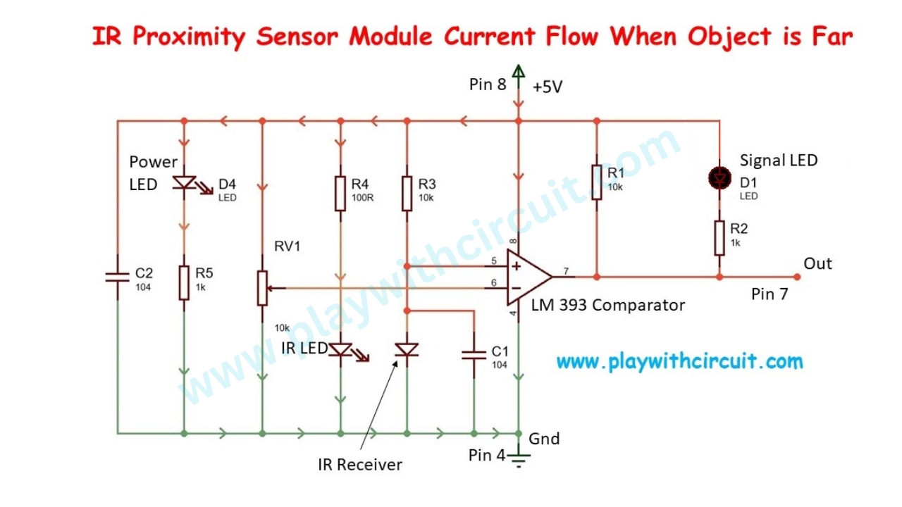
When the object is far from IR sensor then IR Receiver doesn’t get enough IR Radiations emitted by IR LED and reflected by object towards it, hence it acts as nearly open circuit which means potential at positive terminal is approximately equal to 5V which is greater than potential at negative terminal which leads to HIGH output at out pin 7 as well as OUT pin of our Module. Hence Signal LED doesn’t glow.
What Happens when the Object is Near
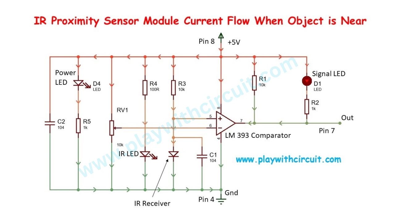
When the object is at close proximity from IR sensor then IR Receiver get enough IR Radiations which is emitted by IR LED and reflected by the object. Hence it acts as close circuit which means potential at positive terminal is becomes less than potential at negative terminal which leads to LOW output at out pin 7 as well as OUT pin of our Module. Hence current will flow through Signal which is shown in above picture and hence LED turns ON.
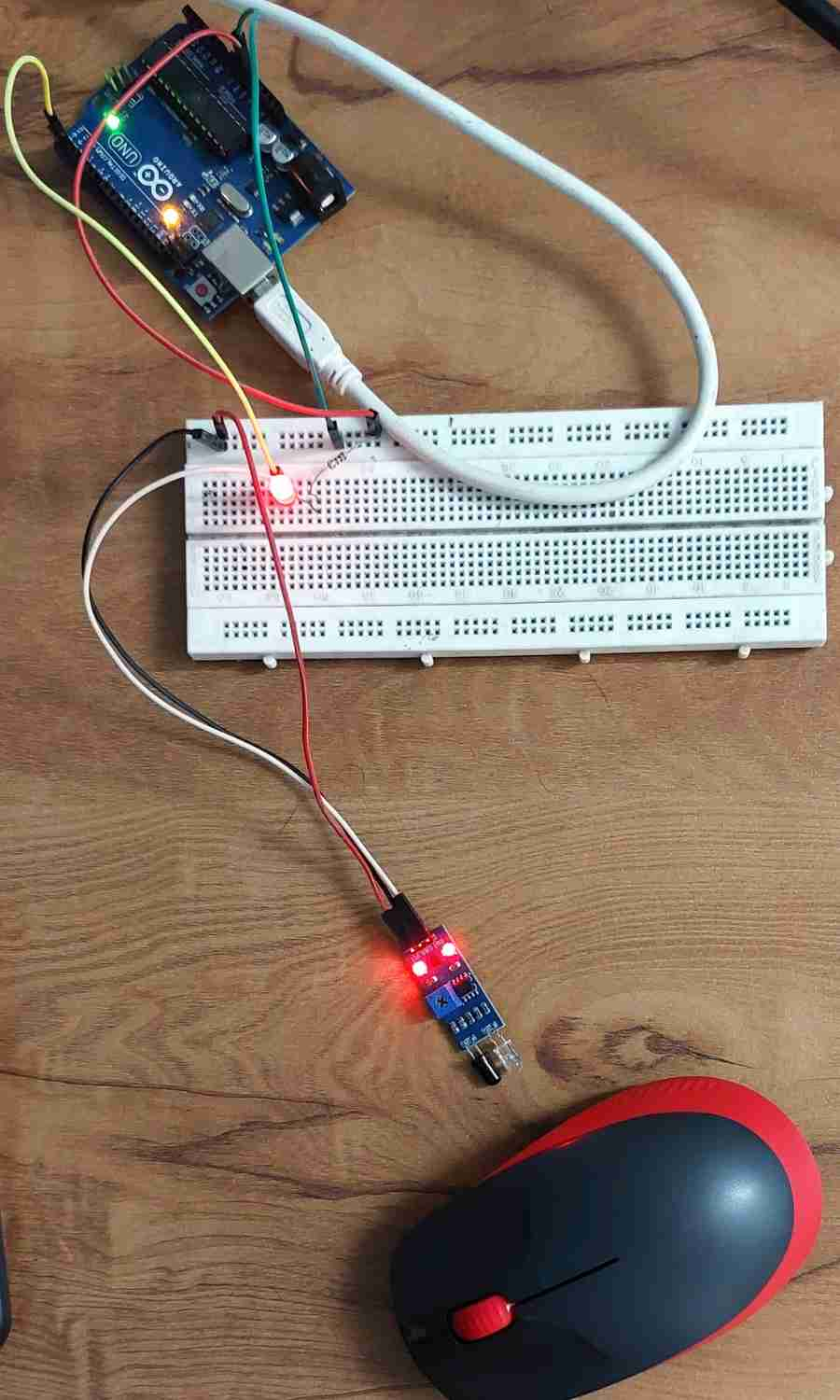
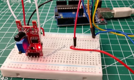
Wiring IR Sensor Module with Arduino
Now we have a clear understanding of how an IR sensor works, we can interface IR sensor to Arduino as shown below.
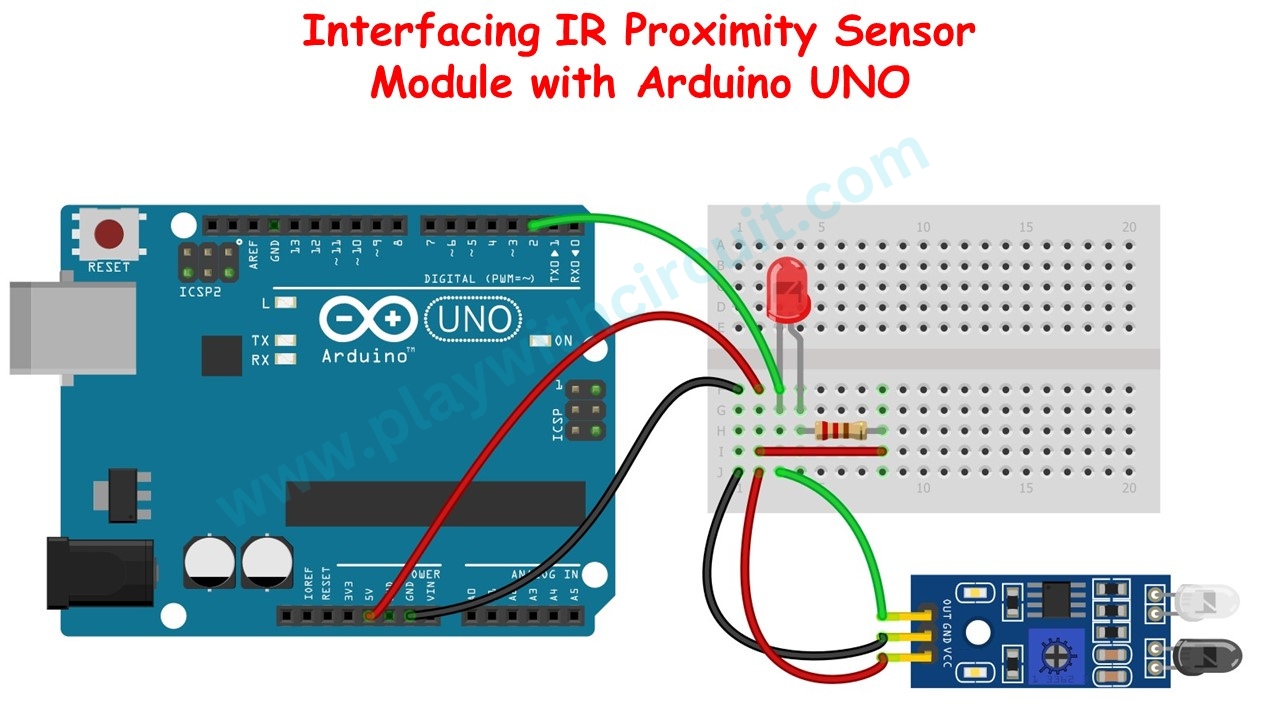
In the above wiring diagram, Arduino Uno is connected with the IR Proximity Sensor. The VCC pin of sensor is connected to the 5V pin on the Arduino. The GND pin is connected to the GND pin on the Arduino. The OUT pin, which provides the sensor’s digital output, is connected to negative terminal of RED LED and digital pin 2 on the Arduino.
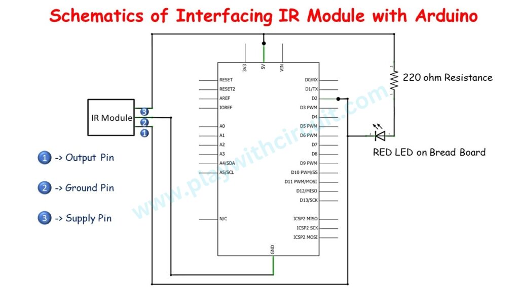
| IR Proximity Sensor | Arduino Side |
|---|---|
| Vcc | 5V Supply |
| GND | Ground Pin |
| OUT | Pin 2 |
The schematics of above connection is shown below:
Components Used
Arduino Code
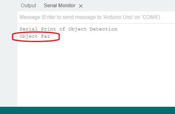
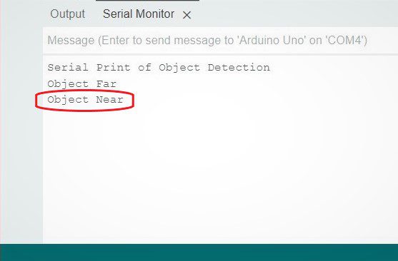
The Arduino Code is written like this, as soon as the object is detected by the Sensor then “Object Near ” will be printed on serial terminal at 9600 Baud-rate. When the object is moved away from the Sensor “Object Far” will be printed on the terminal.
/*
Interfacing IR Sensor Module with Arduino
by www.playwithcircuit.com
*/
int sensorInput = 2;  // Output for IR sensor input for controller
int sersorReturn = 0;
char printOnce = 0;

void setup() {
  // setup code here, run once
  pinMode(sensorInput, INPUT);  // declare sensor pin as input pin
  Serial.begin(9600);
  Serial.print("Serial Print of Object Detection\n");
}

bool checkSensor(int* sensorReturnValue) {
  int sersorValue1, sersorValue2;
  bool boolReturn;
  sersorValue1 = digitalRead(sensorInput);  // read input value
  delay(20);
  sersorValue2 = digitalRead(sensorInput);  // read input value
  if (sersorValue1 == sersorValue2) {
    boolReturn = true;
    *sensorReturnValue = sersorValue1;
  } else {
    boolReturn = false;
  }

  return boolReturn;
}

void loop() {
  bool boReturn = 0;
  // main code here, run repeatedly
  boReturn = checkSensor(&sersorReturn);

  if (boReturn == true) {
    if (sersorReturn == LOW) {   // When object is near then LOW is received at out pin
      if (printOnce == 1) {
        Serial.print("Object Near\n");
        printOnce = 0;
      }
    } else {
      if (printOnce == 0) {    // When object is Far then HIGH is received at out pin
        Serial.print("Object Far\n");
        printOnce = 1;
      }
    }
  }
}
Output
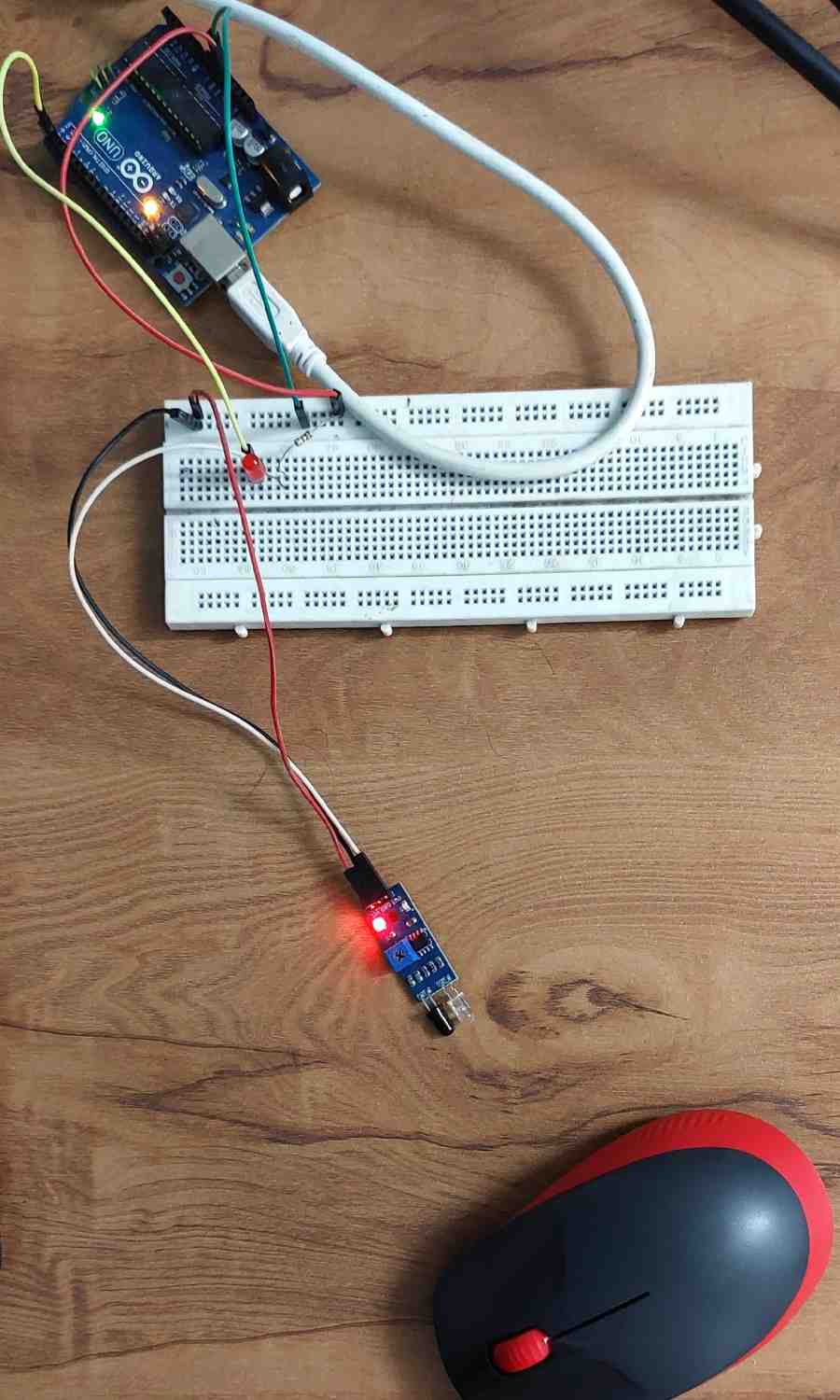
When the circuit is powered up then object is Far from the Sensor. Hence following output is present on serial terminal:
When the Object is placed near the sensor then
The Serial output is like this:
Code Explanation
Initially the initialization of sensor input pin and declaration of variables to save data is done in code using below code lines.
int sensorInput = 2;  // Output for IR sensor input for controller
int sersorReturn = 0;
char printOnce = 0;
Now the setup() function is written to set mode of pin 2 as input pin and pins pin 0 and pin 1 are initialized as Rxd and Txd pins for Serial Input and Serial Output. Currently we will be using only Txd pin to send data over serial port to the Terminal Software present in Arduino IDE.
void setup() {
  // setup code here, run once
  pinMode(sensorInput, INPUT);  // declare sensor pin as input pin
  Serial.begin(9600);
  Serial.print("Serial Print of Object Detection\n");
}
Now checkSensor() function is written, which returns the status of pin 2 in the function’s output pointer variable sensorReturnValue. The function is written such that to avoid any false triggering of the detection of object hence pin 2 is read at two difference time instance at a difference of 20 ms when both the instances shown same results then only it is confirmed that object is detected or not. Hence when the return value of checkSensor() function is TRUE the only the pointer variable sensorReturnValue should be checked.
bool checkSensor(int* sensorReturnValue) {
  int sersorValue1, sersorValue2;
  bool boolReturn;
  sersorValue1 = digitalRead(sensorInput);  // read input value
  delay(20);
  sersorValue2 = digitalRead(sensorInput);  // read input value
  if (sersorValue1 == sersorValue2) {
    boolReturn = true;
    *sensorReturnValue = sersorValue1;
  } else {
    boolReturn = false;
  }

  return boolReturn;
}
Now finally loop() function is written which calls checkSensor() function to check the status of pin 2 and its return value is saved in variable boReturn. Next part of code will only run when variable boReturn is TRUE. This is achieved using if statement.
When the sersorReturn is LOW then string “Object Near” will be sent to terminal and when its value is HIGH then string “Object Far” will be sent to terminal. This is achieved by using function Serial.print().
And the String is print only once that is taken care by printOnce variable along with another if else logic statement.
void loop() {
  bool boReturn = 0;
  // main code here, run repeatedly
  boReturn = checkSensor(&sersorReturn);

  if (boReturn == true) {
    if (sersorReturn == LOW) {   // When object is near then LOW is received at out pin
      if (printOnce == 1) {
        Serial.print("Object Near\n");
        printOnce = 0;
      }
    } else {
      if (printOnce == 0) {      // When object is Far then HIGH is received at out pin
        Serial.print("Object Far\n");
        printOnce = 1;
      }
    }
  }
}
Going Further
Now that you understand how an IR proximity sensor works and how to interface it with Arduino, you can explore some practical applications and related sensors to expand your knowledge.
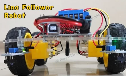
- Build a Line Following Robot Using IR Sensors and Arduino.
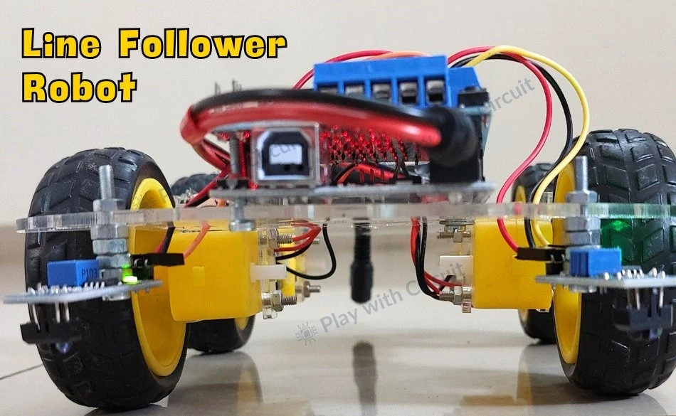
Line Following Robot using Arduino and IR Sensors
Line-following robots use IR sensors to distinguish between black and white surfaces and follow a predefined path. This project is one of the most popular applications of IR sensors in robotics.
- Experiment with Ultrasonic Sensors for Long-Range Object Detection and Distance Measurement.
How HC-SR04 Ultrasonic Sensor Works and Interface with Arduino
IR sensors are suitable for short-range object detection, while ultrasonic sensors provide longer detection distances with high accuracy. Explore this project to learn more.
FAQ’S
What is the range of an IR sensor module?
The detection range of a typical IR proximity sensor module is between 2 cm and 10 cm.
How do I change the range of my IR sensor?
You can modify the detection range or sensitivity of the module by adjusting the potentiometer. Turn the potentiometer clockwise to increase the range and counterclockwise to decrease it.
What is the Input Power of the IR Sensor?
IR sensor operates on 3.3V to 5 V dc.
Can IR sensors detect black objects?
Yes, but black objects absorb infrared radiation and reflect less light, which reduces the detection distance.
What is the difference between an IR sensor and a PIR sensor?
An IR proximity sensor actively emits infrared light and detects reflected signals from nearby objects, whereas a PIR sensor detects changes in infrared radiation emitted by warm objects such as humans and animals.
What is the difference between an IR sensor and an ultrasonic sensor?
IR sensors use reflected infrared light to detect objects, while ultrasonic sensors use sound waves. Ultrasonic sensors generally provide a longer sensing range and are less affected by object color.
Can multiple IR sensors be connected to Arduino?
Yes. Multiple IR sensors can be connected to different digital pins of Arduino and used simultaneously in robotics and automation projects.
