
In many embedded systems, a single microcontroller is often responsible for handling sensors, displays, communication modules, motors, and user inputs simultaneously. As a project becomes more complex, this approach can lead to increased processing overhead and a complicated software architecture. The solution is to divide tasks among multiple microcontrollers that communicate with each other.
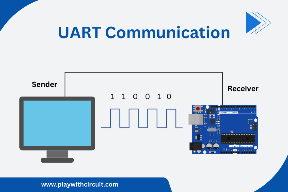
One of the simplest and most reliable ways to establish communication between microcontrollers is through UART (Universal Asynchronous Receiver/Transmitter). UART enables devices to exchange commands and data using only two communication lines, making it ideal for embedded applications where simplicity and efficiency are important.
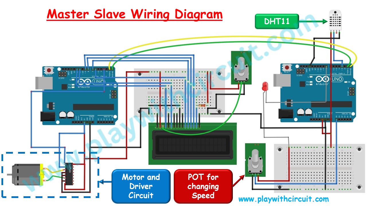
In this project, we will build a master-slave communication system using two Arduino Uno boards connected through UART serial communication. The Master Arduino will send control commands, while the Slave Arduino will handle data acquisition from a DHT11 temperature and humidity sensor and monitor an analog input. Based on the information received from the slave, the master will display real-time data on a 16×2 LCD, control the speed of a DC motor, and remotely switch an LED connected to the slave board.
Understanding Master-Slave Communication
In master-slave communication between two Arduino Boards, one Arduino acts as the Master while the other acts as the Slave. The Master Arduino controls the communication process by sending commands to the Slave Arduino to complete a certain task. Upon receiving a command, the Slave board performs the requested operation and sends the response back to the Master.
The task can be anything from turning ON an LED, getting the sensor value, or controlling the speed of a motor. While the master controls the slave using the commands, the slave does the rest of the computations to do the particular task. Here, communication between the two Arduino boards is established using the UART protocol. UART communication requires only three pins:
- TX (Transmit) – Used to send data
- RX (Receive) – Used to receive data
- GND (Ground) – Provides a common voltage reference for reliable communication
In this project, Master Arduino sends commands to the Slave Arduino via Serial Tx Pin and receives the response of the Slave Arduino using Serial Rx Pin.
The master will send the command:
- To get Temperature data from the Slave board.
- To get Humidity data from the Slave board.
- To get the Analog Value Read from the A0 input connected to the Slave board.
- To turn the LED ON/OFF based on the value of Analog Input.
The Slave Arduino is connected with a DHT11 sensor, an LED, and a 10 kΩ potentiometer. Slave Arduino board gets the temperature, humidity data from the DHT11 sensor and Analog values from the POT connected to one of the Analog Input pins of the Arduino. It continuously acquires sensor readings and stores the latest values. Whenever the Master requests data, the Slave retrieves the requested information and sends it back over the UART interface.
After receiving the responses, the Master Arduino processes the data and displays the temperature, humidity, motor speed, and LED status on a 16×2 LCD display. Based on the analog value received from the Slave, the Master also controls the speed of the DC motor and determines whether the LED connected to the Slave should be turned ON or OFF.
Hardware and Software Requirements
Hardware
| Component Name | Quantity | Remarks | Where to Buy |
|---|---|---|---|
| Arduino UNO R3 | 2 | Revision R3 | Amazon |
| LCD | 1 | 16 x 2, to be connected to Master | Amazon |
| Potentiometer | 2 | 10 kΩ | Amazon |
| Resistance | 1 | 220 Ω for using with LCD | Amazon |
| Breadboard | 2 | Full Size | Amazon |
| LED | 1 | Red(5mm OD) | Amazon |
| Resistance | 1 | 100 Ω for using in series with LED | Amazon |
| Temperature Sensor | 1 | DHT11 Temperature And Humidity Sensor | Amazon |
| Power adapter 12V | 2 | One for each Arduino UNO | Amazon |
| Power adapter 5V | 1 | For Supply of Motor using L293D IC | Amazon |
| L293D | 1 | For controlling speed of Motor | Amazon |
| Ceramic Capacitor | 1 | 104 pf for connection at power rails on bread-board | Amazon |
| Connecting Wires | multiple | Required as per breadboard connections | Amazon |
| DC Motor | 1 | 5V DC motor | Amazon |
| DC Fan | 1 | To be connected to Motor's rotor | Amazon |
| USB A/B cable | 1 | To program Arduino UNO | Amazon |
Software
- Arduino IDE, Version 2.1.1 or above installed on your PC
- DHT Sensor Library by Adafruit, Version 1.4.6 installed in Arduino IDE
- LiquidCrystal Library by Arduino, Version 1.0.7 installed in Arduino IDE
💡Must Read
To know about the basics of Serial UART Communication go to this Article.
What is UART and How it Works?
This article will give you more in-depth information about UART communication protocol and its configuration parameters.
To know about basic functions provided by Arduino related to UART serial communication go to this article.
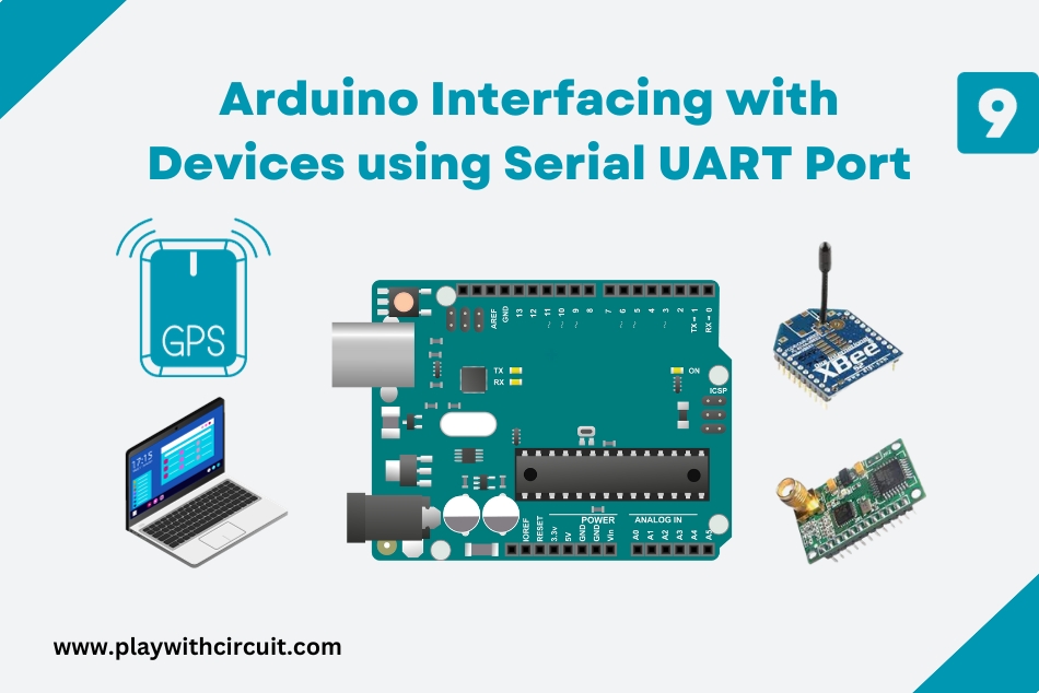
How to Use Serial UART Port of Arduino and Serial Monitor Tool in Arduino IDE
This article will give you information about Arduino UART Serial Communication and core library functions of the serial UART Port.
To know about how LCD works go to this article.
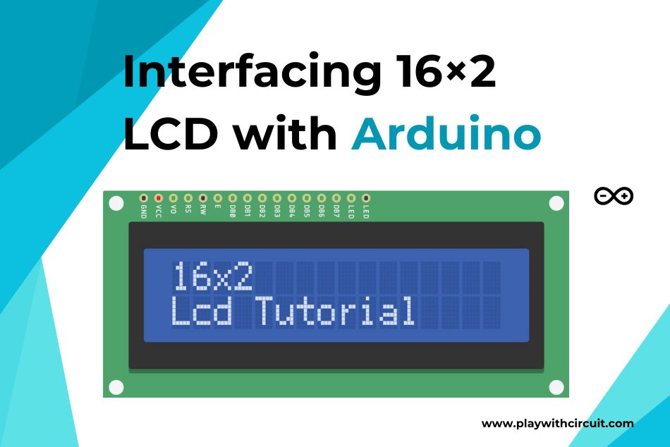
Interfacing 16×2 LCD with Arduino
In this tutorial, you will learn how to interface a 16×2 LCD with an Arduino UNO and how to Display custom characters on the LCD.
Project Simulation
Before working on the hardware, let’s simulate the project in simulation software.
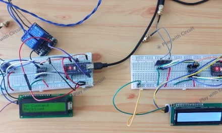
In the above simulation, we can see two Arduino boards communicating with each other via serial pins. When we change the temperature of the temperature sensor connected to the slave, it is shown in the LCD connected to the master board. Similarly, when the Humidity is changed, it is updated in the LCD connected to the master board.
When the value of the Variable resistor RV1 changes, it is immediately reflected on the LCD connected to the Master board. When the speed (SP) is greater than 50, then the Master board sends the command to the slave board to turn ON the Red LED connected to the slave board.
Schematic Diagram
Here we will discuss the schematic diagram of the project.
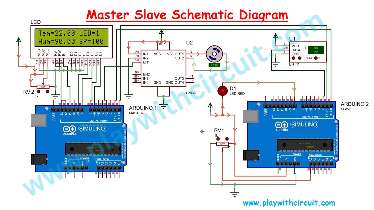
Master Side Connections
In the above schematic diagram, we can see a 16×2 LCD is connected to the Master Arduino Board. We will be using the LCD in 4-bit mode that is, only the last 4 data lines (D4 to D7) will be used for sending command/data to the LCD. A 10K POT is connected at pin 3 on the LCD to control VEE voltage. Data pins D0 to D3 are connected to GND.
| Pin No. | LCD Side Pin Name | Arduino 1 Side/Bread-board Connection |
|---|---|---|
| 1 | VSS/GND (Pin 1) | Connected to Ground |
| 2 | VDD/VCC (pin 2) | Connected to 5V |
| 3 | VEE/Vo (Pin 3) | Connected to Variable pin of 10k POT to Control Contrast of LCD |
| 4 | RS (Pin 4) | pin 12 |
| 5 | R/W (pin 5) | Connected to Ground |
| 6 | E (Pin6) | pin 11 |
| 7 | D0 (pin 7) | Connected to Ground |
| 8 | D1 (pin 8) | Connected to Ground |
| 9 | D2 (pin 9) | Connected to Ground |
| 10 | D3 (pin 10) | Connected to Ground |
| 11 | D4 (pin 11) | pin 9 |
| 12 | D5 (pin 12) | pin 8 |
| 13 | D6 (pin 13) | pin 7 |
| 14 | D7 (pin 14) | pin 6 |
| 15 | LED(+)(Pin 15) | Connected to VCC via 220ohm resistor |
| 16 | LED(-)(Pin 16) | Connected to Ground |
Pin3 of the Arduino Uno is used to control the Enable pin of the L293d IC, which in turn controls the Speed of the Motor connected to the IC.
The motor is connected to the Pin 3 and Pin 6 of the L293D IC. Another way to connect the motor is to connect one pin of the Motor to Pin 3 of the L293D IC and another to the GND both ways it work.
Please note that Vcc(5V) is connected to pin 16 of the L293D H-bridge motor driver IC. The motor is driven by the supply which is connected to the Pin 8 of the driver IC. Currently, we are using an external power adapter to supply power to the Motor.
❕Note
Do not use power from the Arduino board because when the Speed of the Motor increases, it draws a higher current which leads to the reset of Arduino UNO.
| Pin No. | L293D Pin Name | Connected To |
|---|---|---|
| 1 | Enable 1 | Pin 3 of Arduino 1 |
| 2 | Input 1 | Connected to 5V |
| 3 | Output 1 | Connected to Motor |
| 4 | Gnd | Connected to Ground |
| 5 | Gnd | Connected to Ground |
| 6 | Output 2 | Connected to Motor or It can be N/C |
| 7 | Input 2 | Connected to Ground |
| 8 | Motor Supply | Connected to 5V pin of External Power Adapter |
| 9 | Enable 2 | N/C |
| 10 | Input 3 | N/C |
| 11 | Output 3 | N/C |
| 12 | Gnd | N/C |
| 13 | Gnd | N/C |
| 14 | Output 4 | N/C |
| 15 | Input 4 | N/C |
| 16 | Vcc | Connected to Vcc Pin of Arduino 1 |
❕Note
There are two pins of motor. One pin should be connected to Pin 3 of L293D and another pin can either be connected to pin 6 of L293D IC or it could be connected to GND both way it works. When it is connected to GND then the speed of motor will be comparatively more.
Pin 0(Rx) of the Master Arduino is connected to the Pin 1(Tx) of the Slave Arduino and Pin 1 (Tx) of the Master Arduino is connected to the Pin 0 (Rx) of the slave Arduino.
Slave Side Connections
Slave is connected with the DHT11 sensor. The data pin of the Temperature sensor is connected to pin 2 of the slave Arduino board. A pot is connected to the A0 Analog Input pin of the slave board. Usually, Analog sensor is connected to A0 pin but here we use a 10k potentiometer to demonstrate the functionality. As the resistance changes voltage across the A0 pin changes and Analog counts in the software change.
An LED is connected to pin 8 of the Arduino UNO. It is controlled by the Master. The State of the LED changes as per command from the Master board.
| Arduino 2 Side pins | Connected To |
|---|---|
| pin 0 | pin 1 of Arduino 1 |
| pin 1 | pin 0 of Arduino 1 |
| pin 2 | Connected to Data pin of the Temperature Sensor |
| pin 8 | Negative Side of LED |
| A0 | Variable pin of POT |
| 5V | Positive pin of LED and One side of POT |
| Gnd | Another Side of POT |
❕Note
Connect the ground Pin of Arduino 1, Arduino 2 and ground pin of 5V power adapter.
DHT11 Temperature and Humidity Sensor
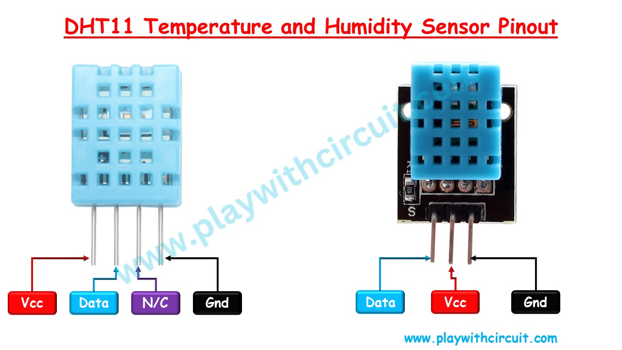
VccThis pin provides the power supply for the sensor. It typically operates within a voltage range of 3.3-5.5 volts.
DataThis pin is used for communication between the sensor and the microcontroller.
N/CNot Connected
GndThis pin should be connected to the ground of the microcontroller.
To know more download the datasheet of DHT11 sensor.
Software Overview
Master Side
In the Master’s code, firstly we will be initializing the Serial port to communicate with Slave Arduino and LCD pins to display data received from Salve Arduino.
Data is fetched from the Slave mode in command response format as explained below:
For fetching temperature, the format of command and response shall be
CMD: START_CHAR TEMP_CMD END_CHAR
RESP: START_CHAR TEMP_RSP STATUS BYTE1 BYTE2 BYTE3 BYTE4 END_CHAR
For fetching humidity, the format of command and response shall be
CMD: START_CHAR HUMIDITY_CMD END_CHAR
RESP: START_CHAR HUMIDITY_RSP STATUS BYTE1 BYTE2 BYTE3 BYTE4 END_CHAR
For fetching speed, the format of command and response shall be
CMD: START_CHAR SPEED_CMD END_CHAR
RESP: START_CHAR SPEED_RSP STATUS BYTE1 END_CHAR
To turn ON the LED connected to the slave Arduino
CMD: START_CHAR LED_ON_CMD END_CHAR
RESP: START_CHAR LED_ON_RSP STATUS END_CHAR
To turn OFF the LED connected to the slave Arduino
CMD: START_CHAR LED_OFF_CMD END_CHAR
RESP: START_CHAR LED_OFF_RSP STATUS END_CHAR
The commands shall be sent by the Master Arduino to the Slave Arduino and then the Master waits for the Slave to respond. As soon as the slave replies, the master Arduino updates the LCD.
Slave Side
In the Slave’s code firstly, we will be initializing the Serial port to communicate with the Master Arduino and DHT11 temperature and humidity sensor pin. Subsequently, the pins of the LED and Analog Input are also initialized.
On the Slave Side, the slave boards get the value of temperature and humidity from the DHT11 Temperature and Humidity Sensor and Analog Input cyclically. Similarly, the value of Analog Input is also read cyclically and saved in a global structure.
The commands will be received in the Serial Event generated when command bytes are received in Arduino. As soon as the complete command is received it is checked for integrity. If a valid command is received, a response is sent based on the command received.
Master Arduino Code
#include "master.h"

#define MOTOR_PIN 3

void setup() {
  // set up the LCD's number of columns and rows:
  lcd.begin(16, 2);
  // set the cursor to (column = 0,row = 0)
  lcd.setCursor(0, 0);
  lcd.print("Master Slave");
  lcd.setCursor(0, 1);
  // set the cursor to (column = 0,row = 1)
  lcd.print("Demo");
  // provide delay of 2 second
  delay(300);
  //Initialize serial and wait for port to open:
  Serial.begin(9600);
  while (!Serial) {
    ;  // wait for serial port to connect. Needed for native USB
  }
  pinMode(MOTOR_PIN, OUTPUT);  // declare Motor pin to be an output
}

void loop() {
  getTempearture();
  getHumidity();
  getSpeed();
  setMotorSpeed();
  lcdUpdate();
}

void setMotorSpeed() {
  if (paramerters.Status[SPD_STA_INDX] == STATUS_OK) {
    analogWrite(MOTOR_PIN, map(paramerters.Speed,0,100,0,255));  // set the Speed of Motor
  }
}

// For temperture
// CMD : START_CHAR TEMP_CMD END_CHAR
// RESP: START_CHAR TEMP_RSP STATUS BYTE1 BYTE2 BYTE3 BYTE4 END_CHAR
void getTempearture() {
  float temp;
  float *ptemp = &temp;
  unsigned char cmdBuffer[3] = { START_CHAR, TEMP_CMD, END_CHAR };
  unsigned char rspBuffer[10] = { 0 };
  unsigned char rspIndex = 0;
  Serial.write(cmdBuffer, 3);
  while (Serial.available() == 0)
    ;
  do {
    rspBuffer[rspIndex++] = Serial.read();
    // this delay is provided because it takes approx 10 ms to receiev a new character at 9600 baurdrate
    delay(10);
  } while (Serial.available() != 0);
  if ((rspBuffer[0] == START_CHAR) && (rspBuffer[1] == TEMP_RSP) && (rspBuffer[7] == END_CHAR)) {
    if (rspBuffer[2] == STATUS_OK) {
      ptemp = (float *)(rspBuffer + 3);
      paramerters.Temperature = *ptemp;
    }
    paramerters.Status[TEM_STA_INDX] = rspBuffer[2];
  }
}

// For humidity
// CMD : START_CHAR HUMIDITY_CMD END_CHAR
// RESP: START_CHAR HUMIDITY_RSP STATUS BYTE1 BYTE2 BYTE3 BYTE4 END_CHAR
void getHumidity() {
  float hum;
  float *phum = &hum;
  unsigned char cmdBuffer[3] = { START_CHAR, HUMIDITY_CMD, END_CHAR };
  unsigned char rspBuffer[10] = { 0 };
  unsigned char rspIndex = 0;
  Serial.write(cmdBuffer, 3);
  while (Serial.available() == 0)
    ;
  do {
    rspBuffer[rspIndex++] = Serial.read();
    // this delay is provided because it takes approx 10 ms to receiev a new character at 9600 baurdrate
    delay(10);
  } while (Serial.available() != 0);
  if ((rspBuffer[0] == START_CHAR) && (rspBuffer[1] == HUMIDITY_RSP) && (rspBuffer[7] == END_CHAR)) {
    if (rspBuffer[2] == STATUS_OK) {
      phum = (float *)(rspBuffer + 3);
      paramerters.Humidity = *phum;
    }
    paramerters.Status[HUM_STA_INDX] = rspBuffer[2];
  }
}

// For speed
// CMD : START_CHAR SPEED_CMD END_CHAR
// RESP: START_CHAR SPEED_RSP STATUS BYTE1 END_CHAR
void getSpeed() {
  int spd;
  int *pspd = &spd;
  unsigned char cmdBuffer[3] = { START_CHAR, SPEED_CMD, END_CHAR };
  unsigned char rspBuffer[10] = { 0 };
  unsigned char rspIndex = 0;
  Serial.write(cmdBuffer, 3);
  while (Serial.available() == 0)
    ;
  do {
    rspBuffer[rspIndex++] = Serial.read();
    // this delay is provided because it takes approx 10 ms to receiev a new character at 9600 baurdrate
    delay(10);
  } while (Serial.available() != 0);
  if ((rspBuffer[0] == START_CHAR) && (rspBuffer[1] == SPEED_RSP) && (rspBuffer[5] == END_CHAR)) {
    if (rspBuffer[2] == STATUS_OK) {
      pspd = (int *)(rspBuffer + 3);
      paramerters.Speed = *pspd;
    }
    paramerters.Status[SPD_STA_INDX] = rspBuffer[2];
  }
  if (paramerters.Status[SPD_STA_INDX] == STATUS_OK) {
    if (paramerters.Speed >= 50) {
      //it indicates high speed
      setLEDON();
    } else {
      //it indicates low speed
      setLEDOff();
    }
  }
}

// For led ON
// CMD : START_CHAR LED_ON_CMD END_CHAR
// RESP: START_CHAR LED_ON_RSP STATUS END_CHAR
void setLEDON() {
  unsigned char cmdBuffer[3] = { START_CHAR, LED_ON_CMD, END_CHAR };
  unsigned char rspBuffer[10] = { 0 };
  unsigned char rspIndex = 0;
  Serial.write(cmdBuffer, 3);
  while (Serial.available() == 0);
  do {
    rspBuffer[rspIndex++] = Serial.read();
    // this delay is provided because it takes approx 10 ms to receiev a new character at 9600 baurdrate
    delay(10);
  } while (Serial.available() != 0);
  if ((rspBuffer[0] == START_CHAR) && (rspBuffer[1] == LED_ON_RSP) && (rspBuffer[3] == END_CHAR)) {
    if (rspBuffer[2] == STATUS_OK) {
      paramerters.Led_state = 1;
    }
    paramerters.Status[LED_STA_INDX] = rspBuffer[2];
  }
}

// For led OFF
// CMD : START_CHAR LED_OFF_CMD END_CHAR
// RESP: START_CHAR LED_OFF_RSP STATUS END_CHAR
void setLEDOff() {
  unsigned char cmdBuffer[3] = { START_CHAR, LED_OFF_CMD, END_CHAR };
  unsigned char rspBuffer[10] = { 0 };
  unsigned char rspIndex = 0;
  Serial.write(cmdBuffer, 3);
  while (Serial.available() == 0)
    ;
  do {
    rspBuffer[rspIndex++] = Serial.read();
    // this delay is provided because it takes approx 10 ms to receiev a new character at 9600 baurdrate
    delay(10);
  } while (Serial.available() != 0);
  if ((rspBuffer[0] == START_CHAR) && (rspBuffer[1] == LED_OFF_RSP) && (rspBuffer[3] == END_CHAR)) {
    if (rspBuffer[2] == STATUS_OK) {
      paramerters.Led_state = 0;
    }
    paramerters.Status[LED_STA_INDX] = rspBuffer[2];
  }
}

void lcdUpdate() {
  lcd.clear();

  // DisplaY Temperature
  // set the cursor to (column = 0,row = 0)
  lcd.setCursor(0, 0);
  lcd.print("Tem=");
  if (paramerters.Status[TEM_STA_INDX] == STATUS_OK) {
    lcd.print(paramerters.Temperature);
  } else {
    lcd.print("NOK");
  }

  // DisplaY LED Status
  lcd.print(" LED=");
  if (paramerters.Status[LED_STA_INDX] == STATUS_OK) {
    lcd.write(paramerters.Led_state | 0x30);
  } else {
    lcd.print("NOK");
  }

  // Display Humidity
  // set the cursor to (column = 0,row = 1)
  lcd.setCursor(0, 1);
  lcd.print("Hum=");
  if (paramerters.Status[HUM_STA_INDX] == STATUS_OK) {
    lcd.print(paramerters.Humidity);
  } else {
    lcd.print("NOK");
  }

  // Display Speed
  lcd.print(" SP=");
  if (paramerters.Status[HUM_STA_INDX] == STATUS_OK) {
    lcd.print(paramerters.Speed);
    lcd.print('%');
  } else {
    lcd.print("NOK");
  }
}
Slave Arduino Code
#include "slave.h"

#define ALARM_LED 8
#define LED_ON 0
#define LED_OFF 1

char serialInput;
int dataIndex = 0;
char databuffer[10] = { 0 };
bool dataRcvd = false;  // whether the string receiving is completed.
unsigned char rspBuffer[10];

void setup() {
  Serial.begin(9600);          // initialize serial port
  dht.begin();                 // Initialize the DHT sensor
  pinMode(ALARM_LED, OUTPUT);  // Initialize alarm LED
  digitalWrite(ALARM_LED, LED_OFF);
}

void loop() {
  getTemphumidity();
  getSpeed();
  if (dataRcvd == true) {
    // Check for start and end character
    if ((databuffer[0] = START_CHAR) && (databuffer[2] = END_CHAR)) {
      // Check if its the temperature command
      // For temperture
      // CMD : START_CHAR TEMP_CMD END_CHAR
      // RESP: START_CHAR TEMP_RSP STATUS BYTE1 BYTE2 BYTE3 BYTE4 END_CHAR
      if (databuffer[1] == TEMP_CMD) {
        rspBuffer[0] = START_CHAR;
        rspBuffer[1] = TEMP_RSP;
        if (paramerters.Status[TEM_STA_INDX] == STATUS_OK) {
          rspBuffer[2] = STATUS_OK;
          memcpy((rspBuffer + 3), &(paramerters.Temperature), 4);
        } else {
          rspBuffer[2] = STATUS_NOT_OK;
          memset((rspBuffer + 3), 0x00, 4);
        }
        rspBuffer[7] = END_CHAR;
        Serial.write(rspBuffer, 8);
      }
      // Check if it is Humidity command
      // For humidity
      // CMD : START_CHAR HUMIDITY_CMD END_CHAR
      // RESP: START_CHAR HUMIDITY_RSP STATUS BYTE1 BYTE2 BYTE3 BYTE4 END_CHAR
      else if (databuffer[1] == HUMIDITY_CMD) {
        rspBuffer[0] = START_CHAR;
        rspBuffer[1] = HUMIDITY_RSP;
        if (paramerters.Status[HUM_STA_INDX] == STATUS_OK) {
          rspBuffer[2] = STATUS_OK;
          memcpy((rspBuffer + 3), &(paramerters.Humidity), 4);
        } else {
          rspBuffer[2] = STATUS_NOT_OK;
          memset((rspBuffer + 3), 0x00, 4);
        }
        rspBuffer[7] = END_CHAR;
        Serial.write(rspBuffer, 8);
      }
      // Check if it is Speed command
      // For speed
      // CMD : START_CHAR SPEED_CMD END_CHAR
      // RESP: START_CHAR SPEED_RSP STATUS BYTE1 END_CHAR
      else if (databuffer[1] == SPEED_CMD) {
        rspBuffer[0] = START_CHAR;
        rspBuffer[1] = SPEED_RSP;
        if (paramerters.Status[SPD_STA_INDX] == STATUS_OK) {
          rspBuffer[2] = STATUS_OK;
          memcpy((rspBuffer + 3), &(paramerters.Speed), 2);
        } else {
          rspBuffer[2] = STATUS_NOT_OK;
          memset((rspBuffer + 3), 0x00, 2);
        }
        rspBuffer[5] = END_CHAR;
        Serial.write(rspBuffer, 6);
      }
      // For led ON
      // CMD : START_CHAR LED_ON_CMD END_CHAR
      // RESP: START_CHAR LED_ON_RSP STATUS END_CHAR
      else if (databuffer[1] == LED_ON_CMD) {
        rspBuffer[0] = START_CHAR;
        rspBuffer[1] = LED_ON_RSP;
        digitalWrite(ALARM_LED, LED_ON);
        rspBuffer[2] = STATUS_OK;
        rspBuffer[3] = END_CHAR;
        Serial.write(rspBuffer, 4);
      }
      // For led OFF
      // CMD : START_CHAR LED_OFF_CMD END_CHAR
      // RESP: START_CHAR LED_OFF_RSP STATUS END_CHAR
      else if (databuffer[1] == LED_OFF_CMD) {
        rspBuffer[0] = START_CHAR;
        rspBuffer[1] = LED_OFF_RSP;
        digitalWrite(ALARM_LED, LED_OFF);
        rspBuffer[2] = STATUS_OK;
        rspBuffer[3] = END_CHAR;
        Serial.write(rspBuffer, 4);
      }
    }
    dataRcvd = false;
    memset(databuffer, 0x00, sizeof(databuffer));
  }
}

void getTemphumidity() {
  static unsigned long int previousTick = 0;
  static unsigned long int currentTick;

  float temperature;
  float humidity;

  currentTick = millis();
  if ((currentTick - previousTick) >= 100) {
    previousTick = currentTick;
    // Read temperature and humidity from the DHT sensor
    temperature = dht.readTemperature(false);
    humidity = dht.readHumidity();

    // Check if the sensor reading is valid (non-NaN)
    if (!isnan(temperature)) {
      paramerters.Temperature = temperature;
      paramerters.Status[TEM_STA_INDX] = STATUS_OK;
      // Serial.print("Temperature: ");
      // Serial.print(temperature);
    } else {
      paramerters.Status[TEM_STA_INDX] = STATUS_NOT_OK;
    }

    if (!isnan(humidity)) {
      paramerters.Humidity = humidity;
      paramerters.Status[HUM_STA_INDX] = STATUS_OK;
      // Serial.print(" °F, Humidity: ");
      // Serial.print(humidity);
      // Serial.println("%");
    } else {
      paramerters.Status[HUM_STA_INDX] = STATUS_NOT_OK;
    }
  }
}

void getSpeed() {
  int analogPin = A0;  // potentiometer wiper (middle terminal) is connected to analog pin 0
  int analogVal = 0;   // variable to store the value read
  analogVal = analogRead(analogPin);  // read the Analog input pin
  paramerters.Speed = map(analogVal, 0, 1023, 0, 100);
  paramerters.Status[SPD_STA_INDX] = STATUS_OK;
}
/*
  SerialEvent occurs whenever a new data comes in the hardware serial RX. This
  routine is run between each time loop() runs, so using delay inside loop can
  delay response. Multiple bytes of data may be available.
*/
void serialEvent() {
  while (Serial.available()) {
    // get the new byte:
    serialInput = Serial.read();
    databuffer[dataIndex++] = serialInput;
    // if the incoming character is a line feed character '\n', set a flag so the main loop can do something about it
    if (serialInput == END_CHAR) {
      dataRcvd = true;
      dataIndex = 0;
    }
  }
}
Output:
Code, Schematic and Proteus Simulation files Download
FAQ’S
How to communicate between two Arduinos using UART?
Communicating between two Arduinos using UART (Universal Asynchronous Receiver-Transmitter) involves establishing a serial communication link between the two microcontrollers. UART is a popular communication protocol that uses two wires, one for transmitting data (TX) and the other for receiving data (RX). To implement UART communication, both Arduinos should have UART-enabled hardware, such as the Serial communication ports commonly available on Arduino boards.
How to transmit data in UART?
Transmitting data over UART (Universal Asynchronous Receiver-Transmitter) using Arduino involves using the Serial library to send data through the TX (transmit) pin.
Can UART communication support multiple slave devices?
UART communication is primarily used for point-to-point communication between two devices. To communicate with multiple devices, additional hardware or communication protocols such as I2C, SPI, RS485, or CAN Bus are generally preferred.
What are the advantages of using a master-slave architecture?
A master-slave architecture helps distribute tasks among multiple microcontrollers, reduces processing load on a single device, improves system scalability, and simplifies the design of complex embedded systems.

