
RGB LED is an electronic component that consists of three LEDs—Red, Green, and Blue, integrated into a single package. You can produce a wide spectrum of colours through the combination of these primary colours.
RGB LED’s integration with microcontroller platforms like Arduino allows for precise control and customization, making them a favourite among hobbyists and electronics enthusiasts. In this article, we’ll explore the RGB LEDs, their functionality, and how to interface them with Arduino to create captivating lighting effects and colourful projects.
Understanding RGB LED
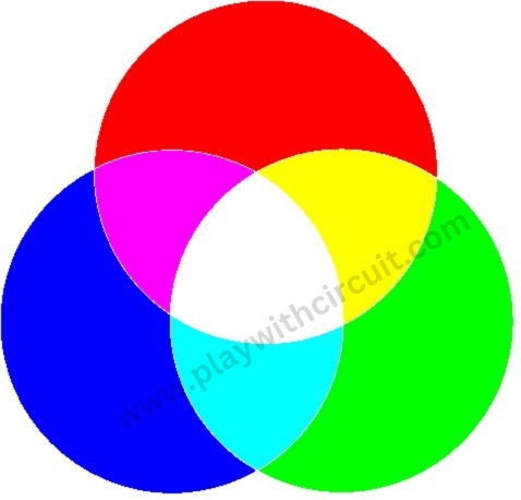
RGB LED can produce an extensive range of colours by adjusting the intensity of each internal LED (Red, Green, and Blue). For instance, combining the full intensity of red and green LEDs creates the colour yellow, while other colours are achieved by different combinations of these primary colours. This capability to generate millions of colours makes RGB LEDs an excellent choice for decorative lighting, LED matrix displays, and creative projects.
RGB LED Hardware Overview
RGB LED consists of 4 terminals, where the first terminal is “R” the second terminal can be “Anode +” or “Cathode –”, the third terminal is “G” and the fourth terminal is “B” as shown below.
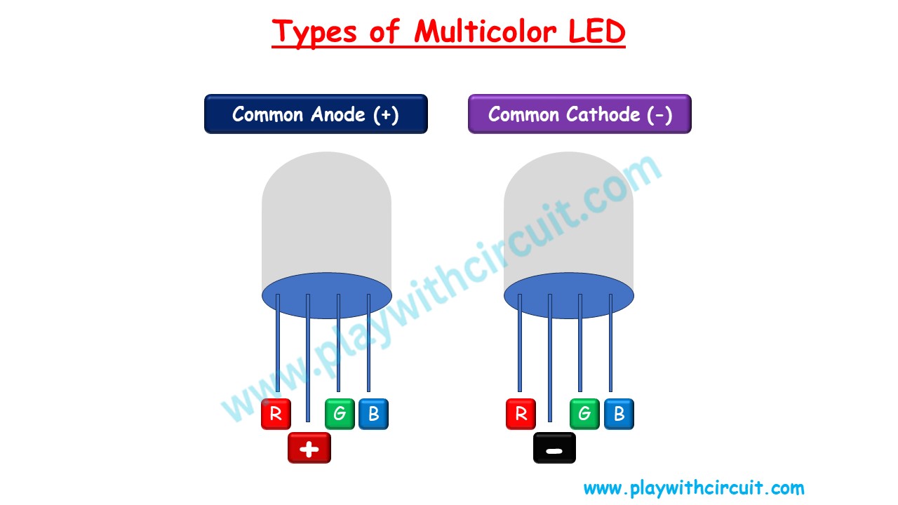
Thus, RGB LED can either have a common anode or a common cathode configuration. These configurations determine how the individual red, green, and blue LEDs within the RGB LED are connected and how you control their colour output.
Common Anode RGB LED
In a common anode RGB LED configuration:
- The anodes (positive terminals) of the red, green, and blue LED chips are all internally connected and lead out as a single common anode pin.
- Each of the three cathodes (negative terminals) is connected to a separate pin, allowing you to control them independently.
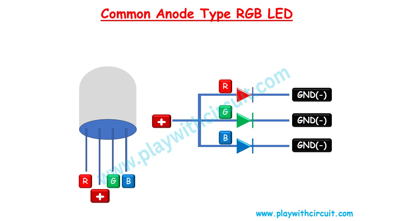
To control the colours in a common anode RGB LED, we connect the common anode pin to the positive voltage supply, typically 3.3V or 5V, and then apply a LOW (0V) signal to the individual cathode pins to activate the corresponding colour. By varying the intensity of each of the red, green, and blue LEDs, you can create a wide range of colours.
Common anode RGB LEDs are popular because they are often easier to control with microcontrollers and integrated circuits.
Common Cathode RGB LED
In a common cathode RGB LED configuration:
- The cathodes (negative terminals) of the red, green, and blue LEDs are all internally connected and lead out as a single common cathode pin.
- Each of the three anodes (positive terminals) is connected to a separate pin for independent control.
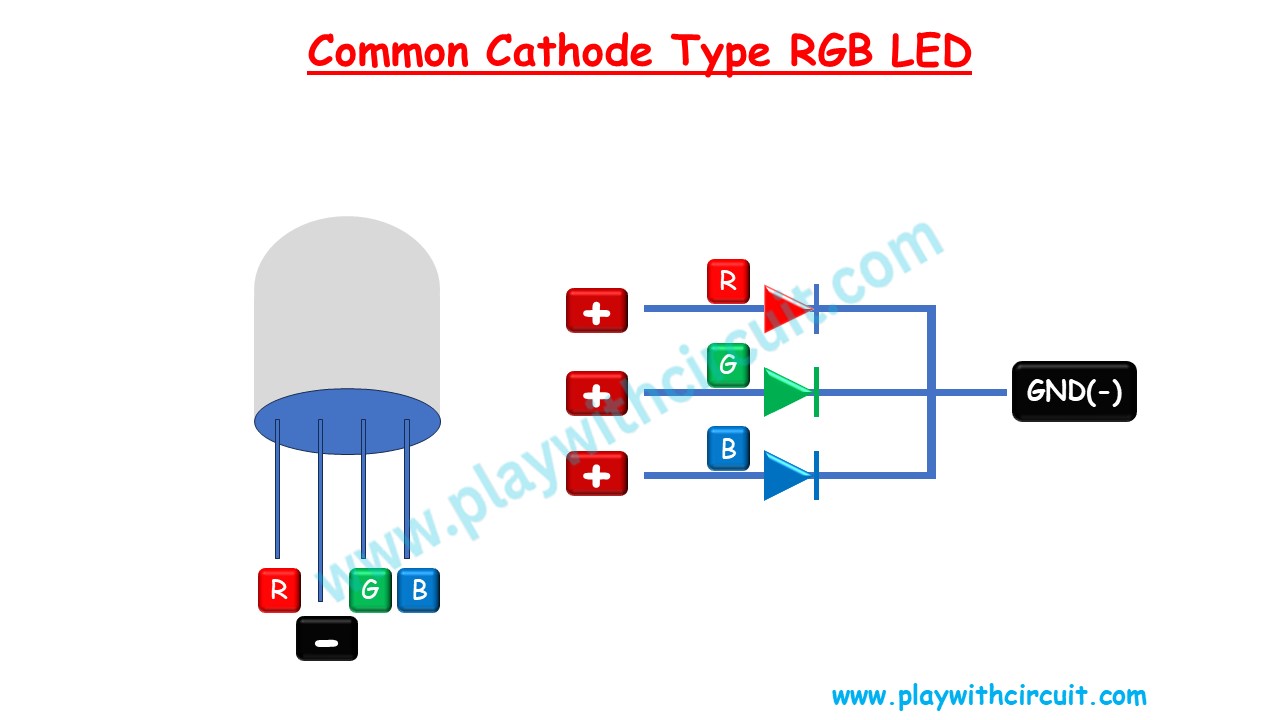
To control the colours in a common cathode RGB LED, you connect the common cathode pin to a negative (0V) voltage supply and apply a HIGH voltage (3.3V or 5V) to the individual anode pins. Like with common anode LEDs, you can vary the intensity of each LED to produce different colours.
❕Note
Make sure to connect a suitable resistance, so that you do not accidentally burn out the LED due to high current.
How to determine whether RGB LED is a common anode or common cathode?
To determine whether an RGB LED is a common anode or a common cathode, you can use a multimeter. To do this, set your multimeter to the diode test mode, which is often represented by a diode symbol. Then, touch the multimeter’s probes to the leads of the LED.
In a common anode RGB LED, you will get a positive voltage reading on the longer lead (the common anode) when the red probe is on the common anode and the black probe is on any of the individual cathodes.
In a common cathode RGB LED, you will get a positive voltage reading on the longer lead (the common cathode) when the red probe is on the common cathode and the black probe is on any of the individual anodes. This method allows you to determine the LED’s configuration by identifying the common connection using the multimeter.
Interfacing one RGB LED with the Arduino UNO
In this circuit, we will be interfacing one RGB LED with Arduino Uno. We will be controlling the different colours of the common cathode LED. We will also mix two different colours to create new colours.
Hardware and Software Requirements
Hardware Requirement
| Component Name | Quantity | Remarks | Where to Buy |
|---|---|---|---|
| Arduino UNO | 1 | Revision R3 | Amazon |
| Resistance | 100 ohms | to connect between common cathode and Gnd | Amazon |
| Bread board | 1 | Full Size | Amazon |
| Multicolour LED | 1 | Common Cathode | Amazon |
| Jumper Wires | 5 | For Breadboard connections | Amazon |
| USB Cable Type A to B | 1 | for programming Arduino UNO | Amazon |
| 12V Supply Adapter | 1 | For providing power to Arduino | Amazon |
Software Requirement
Arduino IDE, Version 2.1.1 or above installed on your PC
Wiring Diagram for Interfacing one RGB LED with the Arduino UNO
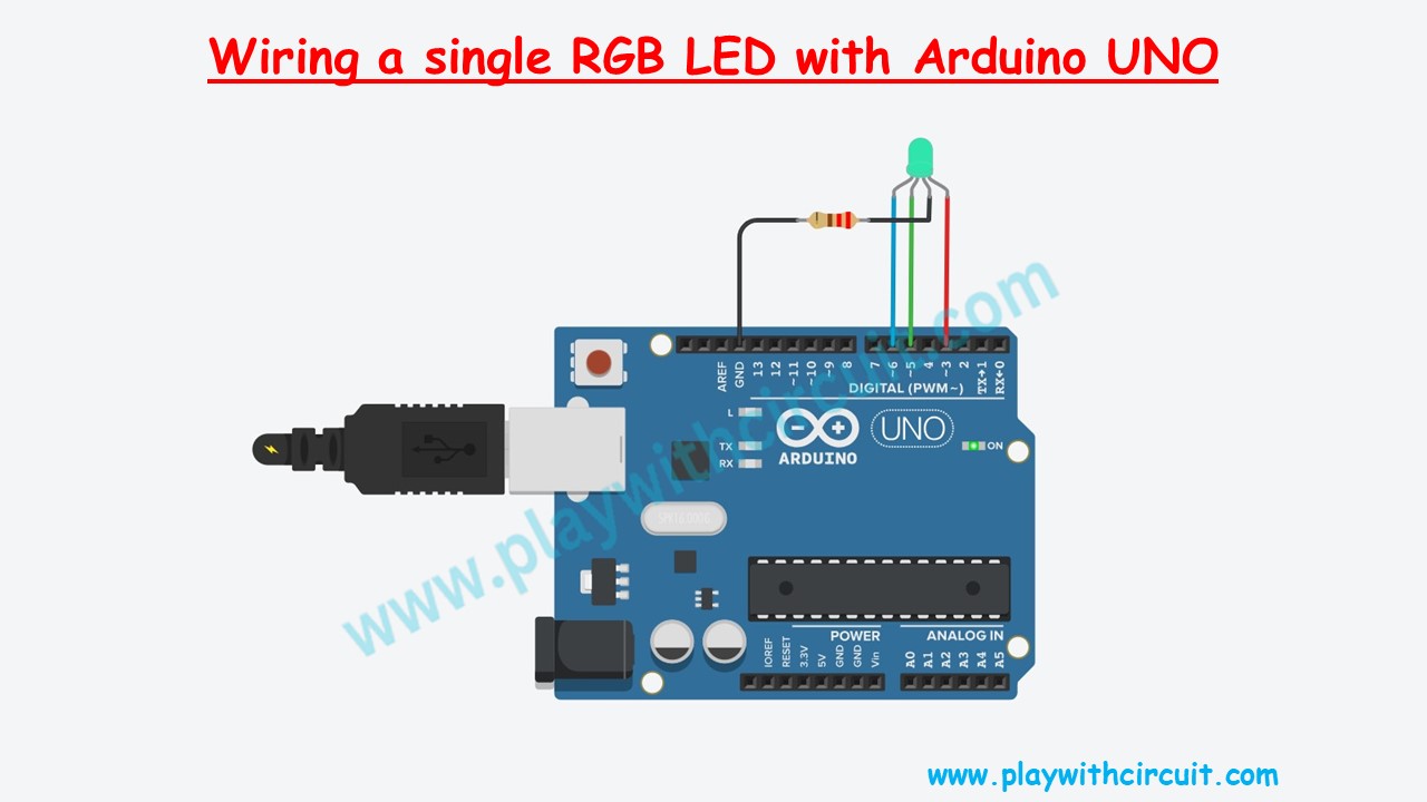
In the above circuit, Arduino UNO board is connected to common cathode RGB LED.
The Red terminal of LED is connected to the pin 3, Green terminal with the pin 5 and Blue terminal with the pin 6 of the Arduino. The Common cathode is connected to the Ground via 220 ohm resistance.
Code
/*
Interfacing RGB LED with Arduino Uno
by www.PlaywithCircuit.com
*/
// Pin definitions
const int redPin = 3;    // Red LED connected to digital pin 3
const int greenPin = 5;  // Green LED connected to digital pin 5
const int bluePin = 6;   // Blue LED connected to digital pin 6

void setup() {
  // Initialize digital pins as outputs pins
  pinMode(redPin, OUTPUT);
  pinMode(greenPin, OUTPUT);
  pinMode(bluePin, OUTPUT);
}

void loop() {
  // Set red color
  digitalWrite(redPin, 1);    // Red ON
  digitalWrite(greenPin, 0);  // Green OFF
  digitalWrite(bluePin, 0);   // Blue OFF
  delay(1000);                // 1 second delay

  // Set green color
  digitalWrite(redPin, 0);    // Red OFF
  digitalWrite(greenPin, 1);  // Green ON
  digitalWrite(bluePin, 0);   // Blue OFF
  delay(1000);                // 1 second delay

  // Set blue color
  digitalWrite(redPin, 0);    // Red OFF
  digitalWrite(greenPin, 0);  // Green OFF
  digitalWrite(bluePin, 1);   // Blue ON
  delay(1000);                // 1 second delay

  // Set purple color
  digitalWrite(redPin, 1);    // Red ON
  digitalWrite(greenPin, 0);  // Green OFF
  digitalWrite(bluePin, 1);   // Blue ON
  delay(1000);                // 1 second delay

  // Set yellow color
  digitalWrite(redPin, 1);    // Red ON
  digitalWrite(greenPin, 1);  // Green ON
  digitalWrite(bluePin, 0);   // Blue OFF
  delay(1000);                // 1 second delay

  // Set cyan color
  digitalWrite(redPin, 0);    // Red OFF
  digitalWrite(greenPin, 1);  // Green ON
  digitalWrite(bluePin, 1);   // Blue ON
  delay(1000);                // 1 second delay

  // Set white color
  digitalWrite(redPin, 1);    // Red ON
  digitalWrite(greenPin, 1);  // Green ON
  digitalWrite(bluePin, 1);   // Blue ON
  delay(1000);                // 1 second delay
}
Code Explanation
In the above code firstly, all three pins of RGB LED are defined as a constant.
In the setup() function the three pin are made output pins. In this code we are using these pins as digital I/O pins.
In the loop() functions firstly the single color is turned ON, firstly red, then green then blue in RGB LED. In the next lines, the combination of two colors is turned ON. Firstly Red and blue colours turned ON to form a purple colour, then red and green to form a yellow color and in the end, green and blue to form a cyan colour. At the end of the loop() function, all three colors are turned ON to produce white light. This can be better understood by the following figure:
Output:
Creating LED Show using Arduino UNO
In this circuit, we will be interfacing multiple RGB LEDs with an Arduino. We will be controlling the brightness of different sections of the RGB LED using Arduino UNO. We will use Pulse Width Modulation technique to change the brightness of the LED and get the desired colours. Pulse Width Modulated signals with different duty cycles are given below.
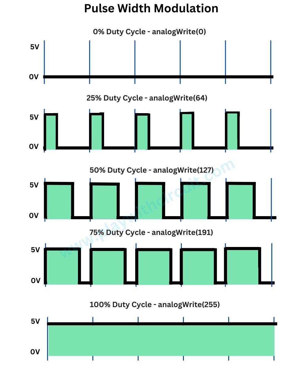
Using PWM we can control the brightness of the RED colour from 0 to 255, hence number of possibilities are 256 similarly using PWM technique number of possibilities of Blue and Green are 256. Hence, total number of combinations could be 256x256x256 = 1,67,77,216. In the below code we will be using pin 3, pin 5 and pin 6 as PWM pins.
In the following code example we will not show all the colours but we will surely create a very good light show.
Hardware and Software Requirements
Hardware Requirement
| Component Name | Quantity | Remarks | Where to Buy |
|---|---|---|---|
| Arduino UNO R3 | 1 | Revision R3 | Amazon |
| Resistance | 100 ohms | to connect between common cathode and Gnd | Amazon |
| Bread board | 1 | Full Size | Amazon |
| Multicolor LED | 3 | Common Cathode | Amazon |
| BC547 | 3 | To connect between Arduino Pins and LED | Amazon |
| Jumper Wires | 15 | For Bread Board Connections | Amazon |
| USB Cable Type A to B | 1 | for programming Arduino UNO | Amazon |
| 12V Supply Adapter | 1 | For providing power to Arduino | Amazon |
Software Requirement
Arduino IDE, Version 2.1.1 or above installed on your PC
Wiring Diagram of Interfacing Multiple RGB LED with Arduino
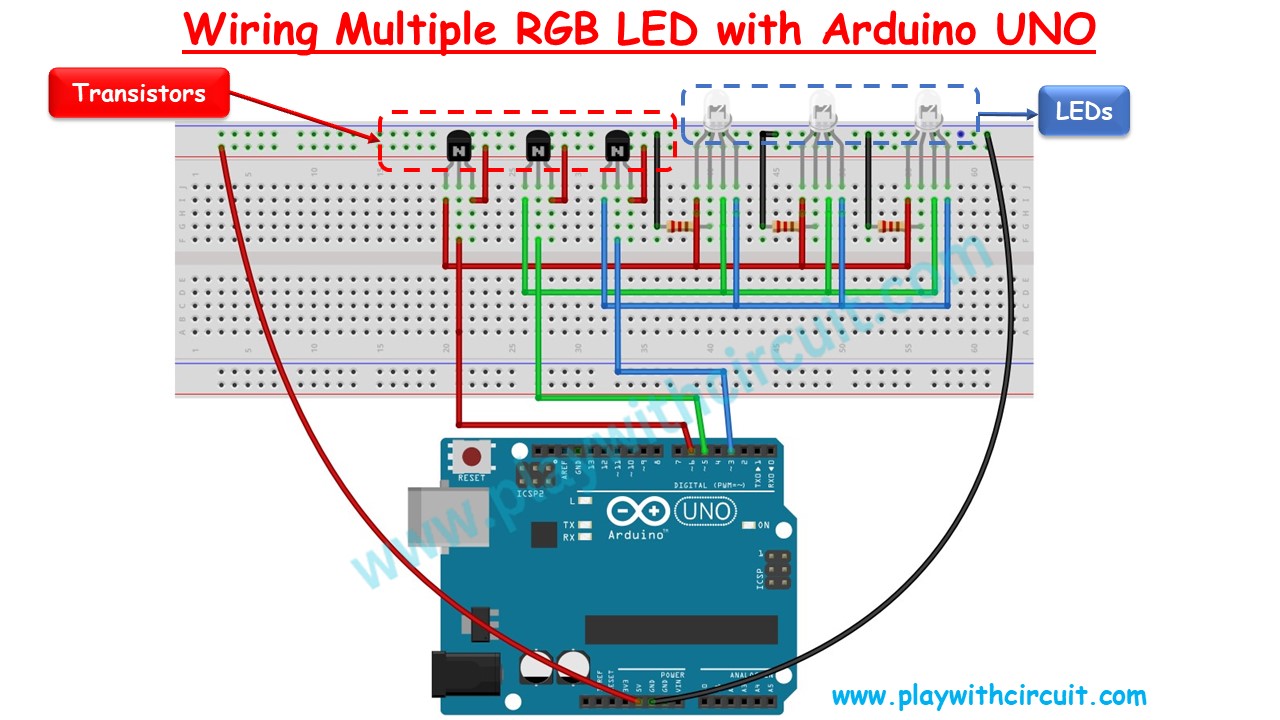
Schematic Diagram
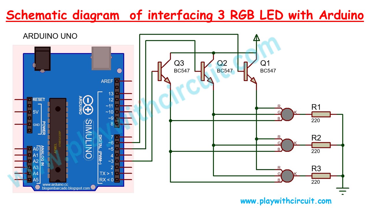
In the above schematic diagram, we can see an Arduino Uno along with three NPN transistors BC547, which controls the current flowing though Red, Green and Blue Terminals of the RGB LEDs.
Pin 6 of the Arduino is connected to the base of Q1 transistor which controls the current though red terminals of all LEDs.
Pin 5 of the Arduino is connected to the base of Q2 transistor which controls the current though green terminals of all LEDs.
Pin 3 of the Arduino is connected to the base of Q3 transistor which controls the current though blue terminals of all LEDs.
All the transistors are connected in common emitter configuration.
- The Emitter pin of the transistor Q1 is connected to Red terminal of all the LEDs.
- The Emitter pin of the transistor Q2 is connected to Green terminal of all the LEDs.
- The Emitter pin of the transistor Q3 is connected to Blue terminal of all the LEDs.
- The Collector pin of all the transistors is connected to the Vcc(5V) of the Arduino board.
❕Note
All the cathodes of the individual LEDs are connected to Gnd Via 220 ohm resistance. This resistance is very important as without it high current will flow through LED which can burn the LED.
We could connect all the LEDs to the Arduino pins directly but Arduino can’t provide enough current for all the LEDs. Hence, we have used the transistors to provide enough current for all the LEDs to glow.
In the above schematics, if you want to add more LEDs, two changes must be made in the above circuit:
-
A base resistance must be added to limit the current through the Arduino pin. In the current configuration also you can add a 1k base resistance.
-
Choose an NPN transistor of a higher current rating to run multiple LEDs. No changes in code are required for multiple LED’s.
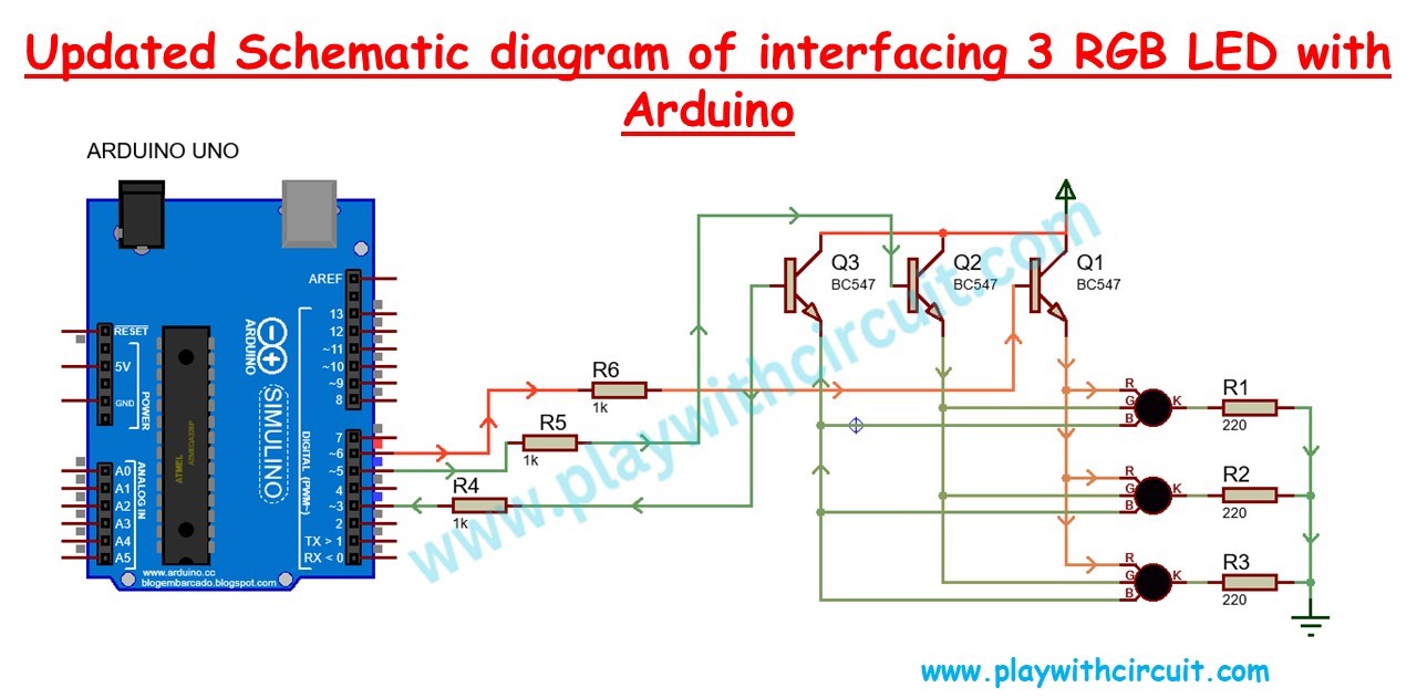
Max current through the emitter of one transistor >= max current through one terminal of LED * number of LED.
The value of the resistance at the cathode of the LEDs can be decreased to increase the brightness of the LED but not too less, else due to high current LED will burn out.
To know more about how current can be controlled using the resistance, go to this article: How do Resistors work?
/*
Interfacing RGB LED with Arduino Uno
by www.PlaywithCircuit.com
*/
// Pin definitions
const int redPin = 6;    // Red LED connected to pwm pin 6
const int greenPin = 5;  // Green LED connected to pwm pin 5
const int bluePin = 3;   // Blue LED connected to pwm pin 3

void setup() {
  // Initialize PWM pins as outputs
  pinMode(redPin, OUTPUT);
  pinMode(greenPin, OUTPUT);
  pinMode(bluePin, OUTPUT);
}
void loop() {
  int i, j;
  analogWrite(redPin, 255);  // Red
  for (i = 0; i < 256; i++) {
    for (j = 0; j < 256; j++) {
      analogWrite(greenPin, i);  // Green
      analogWrite(bluePin, j);   // Blue
    }
  }
  analogWrite(greenPin, 255);  // Green
  for (i = 0; i < 256; i++) {
    for (j = 0; j < 256; j++) {
      analogWrite(redPin, i);   // Red
      analogWrite(bluePin, j);  // Blue
    }
  }
  analogWrite(bluePin, 255);  // Blue
  for (i = 0; i < 256; i++) {
    for (j = 0; j < 256; j++) {
      analogWrite(greenPin, i);  // Green
      analogWrite(redPin, j);    // Red
    }
  }
}
Code Explanation
In the above code firstly all three pins of RGB LED are defined as a constant. At the same time, pin numbers are also assigned.
In the setup function the three pins are made output pins. In this code, we are using these pins as PWM pins. It means the brightness of the individual colors can be controlled.
In the loop function, firstly red color is set at full brightness and blue and green colors are varied, in the next few lines green color is set at full brightness and blue and red colors are varied and later at the end of loop function blue color is set at full brightness and blue and green colors are varied.
The brightness can be varied from 0 to 255 using function analogWrite(pinnumber, value);
Here pinnumber is the pin at which LED terminal is connected to Arduino and value varies from 0 to 255. 0 means colour is turned OFF and 255 means full brightness. The brightness of the colors is varied using the nested for loops like in the code below:
for (i = 0; i < 256; i++) {
    for (j = 0; j < 256; j++) {
      analogWrite(greenPin, i);  // Green
      analogWrite(redPin, j);    // Red
    }
Output
Codes Download
FAQ’S
What are the 4 pins of an RGB LED?
An RGB LED, or Red-Green-Blue Light Emitting Diode, typically features four pins that play distinct roles in controlling the emitted light’s color. The Red (R), Green (G), and Blue (B) pins individually regulate the intensity of their respective colors, allowing for a combination of these primary colors to produce a diverse range of hues. The fourth pin is the common connection, either the positive (anode) or negative (cathode) terminal shared by all colors. By adjusting the voltage on the individual color pins relative to the common pin, you can control the intensity of each color.
Does RGB LED need PWM?
RGB LEDs commonly require Pulse Width Modulation (PWM) to control the intensity of each color (Red, Green, and Blue) individually. PWM is a technique in which an LED is rapidly switched on and off, and the average power delivered determines the perceived brightness of the LED. By adjusting the duty cycle of the PWM signal for each color channel, you can control the brightness levels effectively. PWM offers significant advantages in terms of precise color control, improved power efficiency, and smoother brightness transitions.
How do you make different colors with RGB LED?
To create different colors with an RGB LED, you can adjust the intensity of each primary color: Red, Green, and Blue. The RGB color model is additive, meaning that combining different intensities of these three colors creates various hues.
How many colors can you produce with the RGB LED?
An RGB LED can produce a vast range of colors by combining different intensities of its three primary colors: Red, Green, and Blue. In theory, with each color element having 256 possible intensity levels (commonly used for digital control), an RGB LED could potentially produce 256 ^ 3 = 16,777,216 different color combinations.


