
Whether you want to build a robotic arm or automated door understanding how to control a DC motor’s speed and direction is essential.
DC motors are inexpensive and easy to use. But why can’t we connect the motor directly to an Arduino and start controlling it through code? The reason is that an Arduino’s I/O pins can provide only a small amount of current, while even a small DC motor typically requires much more current to start and run. In addition, motors generate back EMF, when they stop or change direction, which may damage the Arduino.
This is where the L293D Motor Driver IC comes into play. Think of it as a bridge between the Arduino and the motor. Arduino sends low-current control signals to the L293D, and the motor driver safely supplies the higher current needed by the motor.
In this tutorial, you will learn how DC motors work, and how to control DC motor using the L293D motor driver IC and Arduino Uno.
How does a DC Motor Work?
A DC motor operates on the principle of electromagnetic induction that converts electrical energy into mechanical motion. It consists of two main components: the stator (stationary part) and the rotor or armature (moving part). The rotor is generally located on the inside of the motor, while the stator is located on the outside. The rotor consists of coil windings and the stator has either permanent magnets or electromagnetic windings.
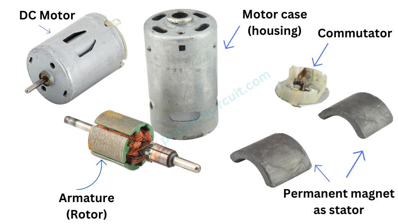
When the DC is applied to the motor, a magnetic field forms within the stator, attracting and repelling the magnets on the rotor. This initiates rotor rotation. To keep the rotor rotating, the motor has a commutator which keeps the polarity of the field flipping.
Controlling a DC Motor
Controlling a DC motor involves regulating its speed and direction of rotation. Here we will use two methods to achieve full control over the motor:
- Pulse Width Modulation (PWM) for speed control
- H-bridge for control over the direction of rotation
PWM – for Motor Speed Control
One method often used to control the speed of a DC motor is Pulse Width Modulation (PWM). In this technique, the average power provided to the motor is modified by delivering voltage given to the motor in a sequence of pulses. The voltage provided to the motor is proportionate to the pulse width generated by a microcontroller.
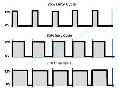
The percentage of time the signal is in the ON state within each pulse period is represented as the Duty Cycle. By regulating the duty cycle, we can effectively control the average power supplied to the DC motor. If the duty cycle is higher, the average power supplied to the DC motor is also higher so the motor rotates faster. If the duty cycle is shorter, the average power supplied to the DC motor is also lower thus the motor rotates at low speed.
This dynamic method of adjusting voltage allows for precise and efficient control of motor speed. The following image shows the PWM method with different duty cycles:
💡Must Read
How to Use Pulse Width Modulation on the Arduino
This article will provide more in-depth information on what is Pulse Width Modulation and how it works?
H-Bridge – for Motor Direction Control
To control the direction of rotation of a motor, we need to reverse the polarity of the voltage applied to the motor. This can be done by using an H-bridge circuit configuration. It consists of four switching elements, typically transistors, arranged in a configuration that resembles the letter “H.” These switches allow the current to flow through the motor in either direction, enabling control over its rotation. By turning ON and OFF two opposite switches, the H-bridge can reverse the polarity of the voltage applied to the motor, effectively changing its direction.
In the below figure we have used four BC547 transistors to make an H-bridge and a motor has been connected between the two pairs.
The ‘1’ in Red represents the transistor is ON and a ‘0’ in blue represents the transistor is OFF.
In the first figure, the Motor is running in a clockwise direction, and in the second figure, the motor is running in a counter-clockwise direction.
L293D Motor Driver IC
The L293D is a popular integrated circuit (IC) used as a motor driver in electronic circuits. Specifically designed for driving small DC motors, it provides two H-bridge configurations within a single chip. The H-bridge arrangement allows the L293D to control the direction of motor rotation. This IC can drive two DC motors simultaneously and the direction of these two motors can be controlled independently.
The L293D also features built-in protection diodes, which help prevent damage to the circuitry from the back electromotive force generated by the motors.
Technical Specifications
- Supply Voltage for Motors (VCC2): 4.5V to 36V
- Supply Voltage for IC (VCC1): 4.5 to 7V
- Logic Input HIGH: 2.3V to VCC1
- Logic Input LOW: –0.3V to 1.5V
- Output Current: 600mA per channel
- Peak Output Current: 1.2A per channel
L293D Motor Driver IC Pinout
The L293D motor driver IC typically has a 16-pins, and the pinout is as follows:
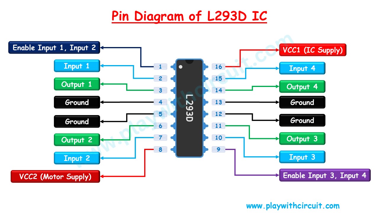
Power Pins: The L293D IC has two input power pins – VCC1 and VCC2
VCC1 This pin provides power to the IC. So, this pin should be connected to 5V.
VCC2 This pin is connected to the motor supply voltage. It is the voltage that gives power to the internal H-Bridge of the IC to drive the motors. The voltage is usually in the range of 4.5V to 36V, depending on the specifications of the IC and the motors.
Ground Pins 4, 5, and 12, 13 are the ground pins of the IC. All 4 Ground pins are internally connected and also act as a heat sink for the IC.
Output Pins: The L293D has four output pins: Output 1 , Output 2 , Output 3, and Output 4 . These pins are used to connect to the terminals of the DC motors. Output 1 and Output 2 can be used to control one motor. The Output 3 and Output 4 can be used to control another motor. So, with this IC, you can control two 4.5 – 36V DC motors respectively.
Direction Control Pins: The L293D has two sets of input pins for controlling the direction of the motors: Input 1/ Input 2 for motor 1 and Input 3/ Input 4 for motor 2. The combination of logic levels applied to these pins determines the direction of rotation (clockwise or counterclockwise) for the connected motors.
| IN1 | IN2 | Spinning Direction |
|---|---|---|
| HIGH(1) | HIGH (1) | Motor OFF |
| LOW (0) | LOW (0) | Motor OFF |
| HIGH (1) | LOW(0) | Forward |
| LOW (0) | HIGH (1) | Backward |
Speed Control Pins: The speed of the motors can be controlled by varying the input voltage on the Enable pins: Enable 1 for Motor 1 and Enable 2 for Motor 2. Applying a PWM (Pulse Width Modulation) signal to these pins allows you to control the average voltage supplied to the motors, thereby adjusting their speed.
To know more download the datasheet of L293D IC:
Working modes of L293D IC
L293D works in two modes:
- Four Motor control without speed and direction control.
- Two Motor control with Direction and Speed control.
Controlling Four Motors with L293D IC
In the above circuit, we can see four DC motors are connected at each output of the L293D IC. The other end of the motors connected to Output 1 and Output 3 is connected to Ground and the motors that are connected to Output 2 and Output 4 are connected to the 24 Volts Supply.
According to the internal working of the L293D IC, it is required that Input 2 and Input 4 should be inverted and hence they are inverted before being given to the IC pins. Pin 16 is connected to the 5V supply and the supply for the motor (24V) is connected to Pin 8 of the IC.
As soon as the logic at the Input pin is set to ‘1’ i.e. HIGH, the motor starts rotating. The rpm of the motor can be seen increasing and after some time rpm becomes stable.
The motors connected to the Output 1 and Output 3 are rotating in the clockwise direction and the motors connected to the Output 2 and Output 4 are rotating in the counterclockwise direction
Controlling Two Motors with L293D IC
In the above circuit, L293D IC is controlling the direction and speed of the two DC motors connected to its outputs.
The first motor is connected between Output 1 and Output 2 whose direction is controlled by Input 1 and Input 2 and the speed is controlled by Enable 1 pin. The second motor is connected between Output 3 and Output 4 whose direction is controlled by Input 3 and Input 4 and the speed is controlled by Enable 2 pin.
When the Duty cycle of the Pulse connected to the enable pin is less, the average power delivered to the motor is less and hence the speed of the motor is less. The power can be seen at the wattmeter connected to the motors in series.
Initially pulse at 50 Hz and duty cycle 50% is given to the Enable pin. Later when the duty cycle is increased to 100% the speed of the motor is increased and the power delivered to the motor is doubled thereby the power consumption of the motor is almost doubled.
When the polarity of all four Inputs is reversed, then first the speed of both the motors is decreased then the direction is reversed, and their speed increases in opposite direction.
Interfacing L293D Motor Driver IC with an Arduino
In this section, we will be interfacing an Arduino UNO with an L293D IC. Two DC motors will be simultaneously controlled using code. The speed of both motors will be controlled using the POT connected to the Analog Input A0. The higher the voltage at A0, higher will be the speed of the motors.
Hardware Requirement
| Component Name | Quantity | Remarks | Where to Buy |
|---|---|---|---|
| Arduino UNO R3 | 1 | Revision R3 | Amazon |
| L293D IC | 1 | 16 Pin DIP Package | Amazon |
| 9V Battery | 1 | For Powering Motor | Amazon |
| 12V DC Motor | 2 | For connection with L293D IC | Amazon |
| POT | 1 | 10k ohm and it will be used to change the speed of DC Motor. | Amazon |
| Breadboard | 1 | Big size | Amazon |
| Connection wires | 25 | For breadboard and Arduino connections | Amazon |
| 12V Supply Adapter | 1 | For providing power to Arduino | Amazon |
Software Requirement
Arduino IDE, Version 2.1.1 or above installed on your PC.
Circuit Diagram
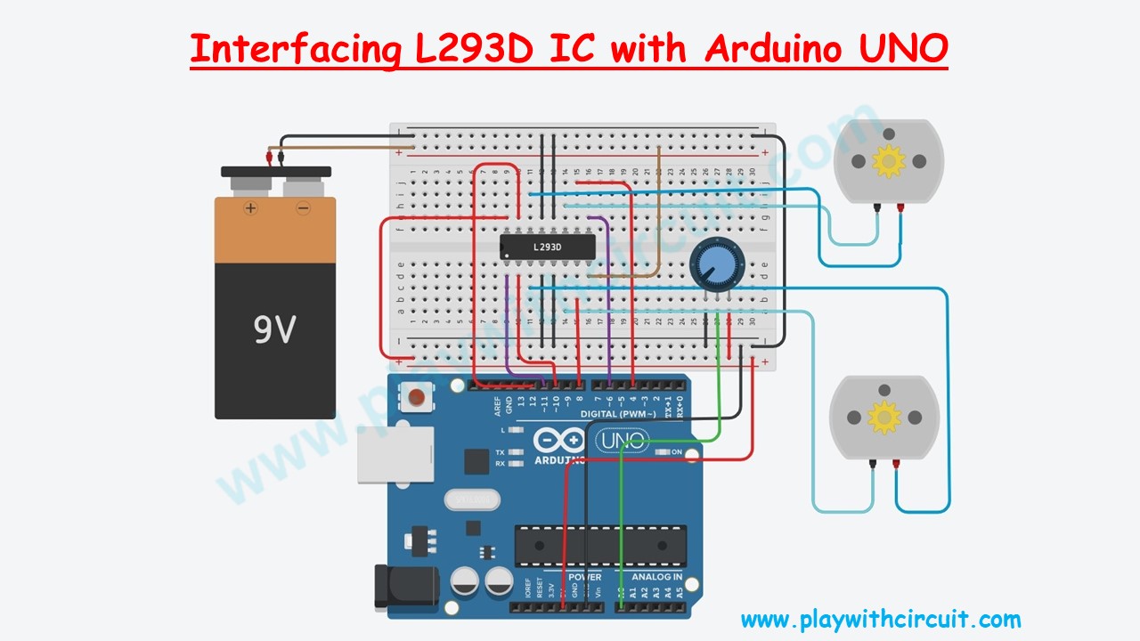
The circuit consists of three main parts: the Arduino Uno, the L293D Motor Driver IC, and two DC motors.
We’ll begin by connecting Pin 16 (VCC1) to the Arduino’s 5V pin to power the IC’s internal logic, and connect Pin 8 (VCC2) to the positive terminal of the 9V Battery. Next, we’ll connect all four GND pins (Pins 4, 5, 12, and 13) of the L293D to the common ground shared by the Arduino and the battery.
Now we’ll connect the two DC motors to the L293D output pins. The positive terminal of the first motor is connected to Output 1 (Pin 3) and negative terminal to Output 2 (Pin 6). The positive terminal of the second motor is connected to Output 4 (Pin 14) and negative terminal to Output 3 (Pin 11).
The direction of each motor is controlled using the L293D input pins, which receive digital signals from the Arduino. We’ll connect Input 1 (Pin 2) to Pin 10 of Arduino and Input 2 (Pin 7) to Pin 8 of Arduino to control the direction of Motor 1. Then, Input 3 (pin 10) to Pin 12 of Arduino and Input 4 (Pin 15) to Pin 4 of Arduino to control the direction of Motor 2. The Arduino changes these pins HIGH or LOW according to the program. The combination of these logic levels determines whether the motor rotates forward, reverse, or stops.
The speed of each motor is controlled through the Enable pins of the L293D. We’ll connect the Enable 1 (Pin 1) to Arduino Pin 11 and Enable 2 (Pin 9) to Arduino Pin 6.
Finally, we’ll connect the 10 kΩ potentiometer to the Arduino’s A0 analog input. Rotating the potentiometer changes the analog voltage read by the Arduino, which is used to increase or decrease the speed of both motors simultaneously.
Here’s a quick reference table for the pin connections:
| IC Side Pin | Connected To |
|---|---|
| Enable In1, In2 (Pin 1) | Pin 11 of Arduino |
| Input 1 (pin 2) | Pin 10 of Arduino |
| Output 1 (Pin 3) | The positive terminal of the First Motor |
| GND (Pin 4) | GND Pin of Arduino |
| GND (pin 5) | GND Pin of Arduino |
| Output 2 (Pin6) | The negative terminal of the First Motor |
| Input 2 (pin 7) | Pin 8 of Arduino |
| Motor Supply (pin 8) | The positive terminal of the 9V Battery |
| Enable Input3, Input4 (Pin 9) | Pin 6 of Arduino |
| Input 3 (pin 10) | Pin 12 of Arduino |
| Output 3 (pin 11) | The negative terminal of the Second Motor |
| GND (pin 12) | GND Pin of Arduino |
| GND (pin 13) | GND Pin of Arduino |
| Output 4 (pin 14) | The positive terminal of the Second Motor |
| Input 4 (Pin 15) | Pin 4 of Arduino |
| IC Voltage Supply (Pin 16) | VCC Pin (5V) of Arduino |
❕Note
The Gnd pin of Arduino and Gnd of the 9V supply should be connected.
Arduino Code
This Arduino sketch controls the speed of two DC motors using the L293D Motor Driver IC. It continuously reads the position of the potentiometer, converts it into a PWM signal, and applies it to both motors. As the potentiometer is rotated, the speed of both motors increases or decreases simultaneously while their direction remains unchanged.
/*
Controlling DC Motors with L293D Motor Driver IC and Arduino
by www.PlaywithCircuit.com
*/
// Define the pins connected to the L293D IC
#define MOTOR_A_EN 11   // Enable pin for Motor A
#define MOTOR_B_EN 6    // Enable pin for Motor B
#define MOTOR_A_IN1 10  // Input 1 for Motor A
#define MOTOR_A_IN2 8   // Input 2 for Motor A
#define MOTOR_B_IN3 12  // Input 3 for Motor B
#define MOTOR_B_IN4 4   // Input 4 for Motor B

// Define the analog pin connected to the potentiometer
#define POT_PIN A0

void setup() {
  // Initialize motor control pins as outputs
  pinMode(MOTOR_A_EN, OUTPUT);
  pinMode(MOTOR_A_IN1, OUTPUT);
  pinMode(MOTOR_A_IN2, OUTPUT);
  pinMode(MOTOR_B_EN, OUTPUT);
  pinMode(MOTOR_B_IN3, OUTPUT);
  pinMode(MOTOR_B_IN4, OUTPUT);

  // Set initial motor speed to zero
  analogWrite(MOTOR_A_EN, 0);
  analogWrite(MOTOR_B_EN, 0);
}

void loop() {
  // Read the analog value from the potentiometer
  int potValue = analogRead(POT_PIN);

  // Map the potentiometer value (0-1023) to motor speed (0-255)
  int motorSpeed = map(potValue, 0, 1023, 0, 255);

  // Control Motor A
  digitalWrite(MOTOR_A_IN1, HIGH);
  digitalWrite(MOTOR_A_IN2, LOW);
  analogWrite(MOTOR_A_EN, motorSpeed);

  // Control Motor B
  digitalWrite(MOTOR_B_IN3, HIGH);
  digitalWrite(MOTOR_B_IN4, LOW);
  analogWrite(MOTOR_B_EN, motorSpeed);
}
Output:
Explanation of Code
The program begins by defining constants for all the Arduino pins connected to the L293D Motor Driver IC and the potentiometer.
// Define the pins connected to the L293D IC
#define MOTOR_A_EN 11   // Enable pin for Motor A
#define MOTOR_B_EN 6    // Enable pin for Motor B
#define MOTOR_A_IN1 10  // Input 1 for Motor A
#define MOTOR_A_IN2 8   // Input 2 for Motor A
#define MOTOR_B_IN3 12  // Input 3 for Motor B
#define MOTOR_B_IN4 4   // Input 4 for Motor B
// Define the analog pin connected to the potentiometer
#define POT_PIN A0
Inside the setup()pinMode()0, ensuring that both motors remain stopped when the Arduino is powered on.
void setup() {
  // Initialize motor control pins as outputs
  pinMode(MOTOR_A_EN, OUTPUT);
  pinMode(MOTOR_A_IN1, OUTPUT);
  pinMode(MOTOR_A_IN2, OUTPUT);
  pinMode(MOTOR_B_EN, OUTPUT);
  pinMode(MOTOR_B_IN3, OUTPUT);
  pinMode(MOTOR_B_IN4, OUTPUT);

  // Set initial motor speed to zero
  analogWrite(MOTOR_A_EN, 0);
  analogWrite(MOTOR_B_EN, 0);
}
The loop()A0 using the analogRead()
Since the analogWrite()map()
// Read the analog value from the potentiometer
int potValue = analogRead(POT_PIN);

// Map the potentiometer value (0-1023) to motor speed (0-255)
int motorSpeed = map(potValue, 0, 1023, 0, 255);
The digitalWrite()
Finally, the calculated PWM value is applied to the Enable pins of both motors using the analogWrite()
// Control Motor A
digitalWrite(MOTOR_A_IN1, HIGH);
digitalWrite(MOTOR_A_IN2, LOW);
analogWrite(MOTOR_A_EN, motorSpeed);

// Control Motor B
digitalWrite(MOTOR_B_IN3, HIGH);
digitalWrite(MOTOR_B_IN4, LOW);
analogWrite(MOTOR_B_EN, motorSpeed);
Project Demonstration
FAQ’S
How many DC motors can the L293D control?
The L293D can independently control two DC motors. It can also drive four DC motors connected in two pairs, but each pair will always rotate together at the same speed and direction.
Why is a motor driver required with an Arduino?
Arduino I/O pins can provide only a limited amount of current, which is insufficient to drive most DC motors. A motor driver allows the Arduino to control the motor while supplying the required current from an external power source.
Can L293D control a 12V motor?
Yes. The L293D supports motor supply voltages from 4.5 V to 36 V, making it compatible with many 12V DC motors, provided the motor current remains within the IC’s specifications.
What is the difference between the L293D and L298N motor drivers?
Both ICs control DC motors using H-bridge circuits. However, the L298N supports higher current, while the L293D is smaller, simpler, and better suited for low-power educational and hobby projects.
