
Motion sensing technology has become a part of our everyday lives. Whether it’s a security light turning ON as someone approaches, an alarm system detecting an intruder, or a smart light that turns ON automatically when someone enters a room. These systems rely on sensors that can detect movement and enable electronic devices to react intelligently.
One of the most widely used PIR sensors is the HC-SR501 that allows you to detect motion and presence of any subject in their field of view. PIR sensor is often referred to as PIR, “Passive Infrared”, “Pyroelectric”, or “PIR motion” sensor.
In this Arduino tutorial, we will learn how a HC-SR501 PIR Sensor works and how to interface it with the Arduino for detecting motion.
How does a PIR sensor work?
The working principle of a PIR sensor is based on the detection of heat emitted by objects in the form of infrared radiation. PIR sensor does not radiate any energy to space, it detects infrared radiation from the environment. Every object above -273°C (absolute zero) emits heat energy in the form of infrared radiation and in the same way the human body emits infrared radiation due to body heat which the PIR sensor detects.
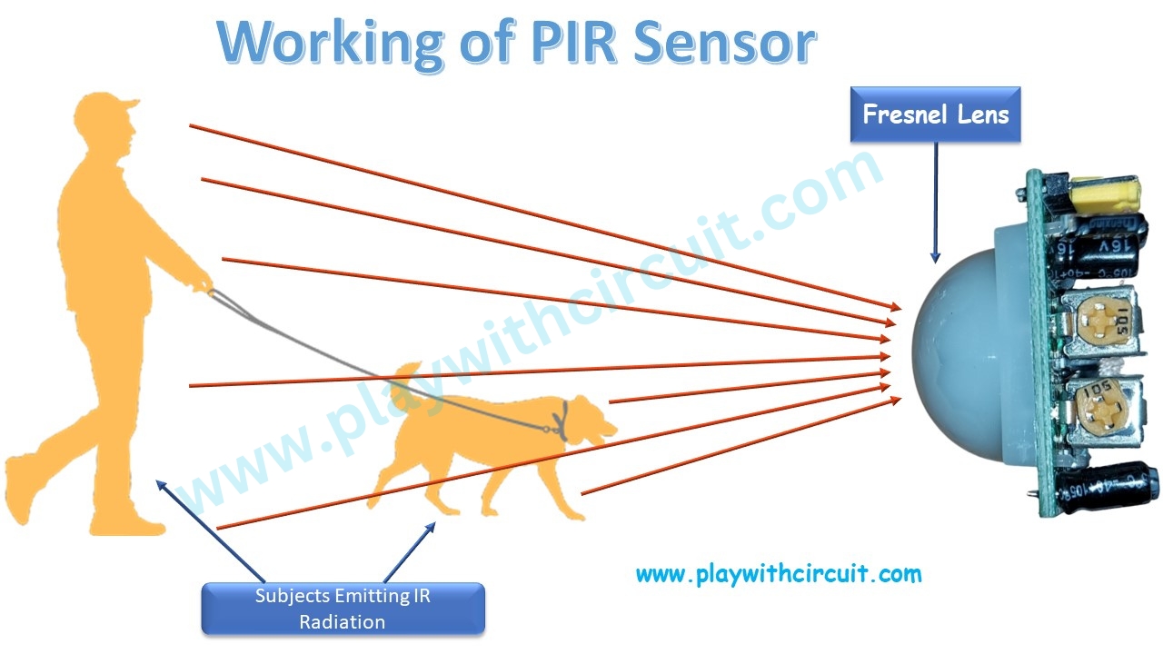
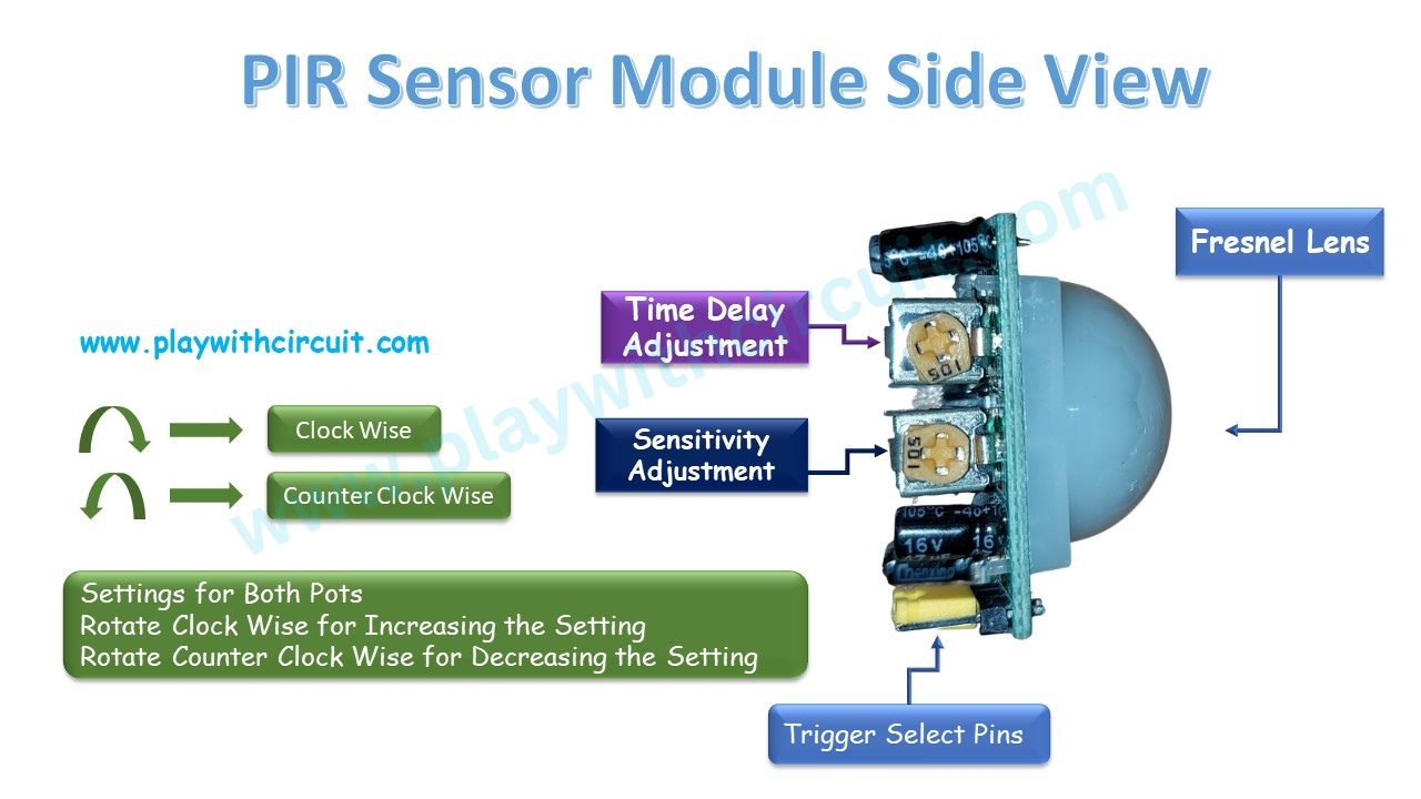
There are two important components present in the PIR sensor, one is Pyroelectric sensor which can detect changes in infrared radiation emitted by objects in its field of view and the other is Fresnel lenses which focus the infrared radiation on the pyroelectric sensor and widen the range of the sensor.
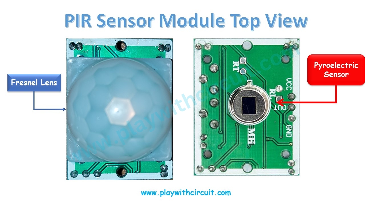
Pyroelectric Sensor
Pyroelectric sensor consists of a pyroelectric material, such as a crystal, that is sensitive to infrared radiation. When a subject moves within the sensor’s range, it causes a temperature change, and the pyroelectric material generates an electric charge. The sensor then converts the Infrared Energy change into a voltage signal that triggers the alarm.
The pyroelectric sensor has two rectangular slots that allow infrared radiation to pass through. two independent infrared sensor electrodes, one providing a positive output and the other a negative output, are linked in such a way that they cancel out each other. This is because they cancel out the ambient radiation and detect any changes in the radiation pattern. So, when one part sees more or less radiation than the other, we get output.
When there is no movement detected around the sensor, the slots detect the same levels of infrared radiation. Thus, the output signal is zero.
But when a human passes by, one-half of the PIR sensor is intercepted first, causing a positive differential change between the two parts of the sensor. The sensor generates a negative differential change when a human intercepts the other half of the sensor. By reading the changes in voltage levels, motion is detected.
Fresnel Lens
A Fresnel lens is a type of optical lens that consists of a series of concentric grooves carved into the plastic. This design allows the lens to focus light in a similar manner to a traditional lens while reducing its thickness and weight.
Light passing through the grooves is refracted, and the grooves act as individual refracting surfaces that gather the light to a specific focal point. This enables the lens to create a wide-angle field of view.
HC-SR501 PIR Motion Sensor Module Pinout
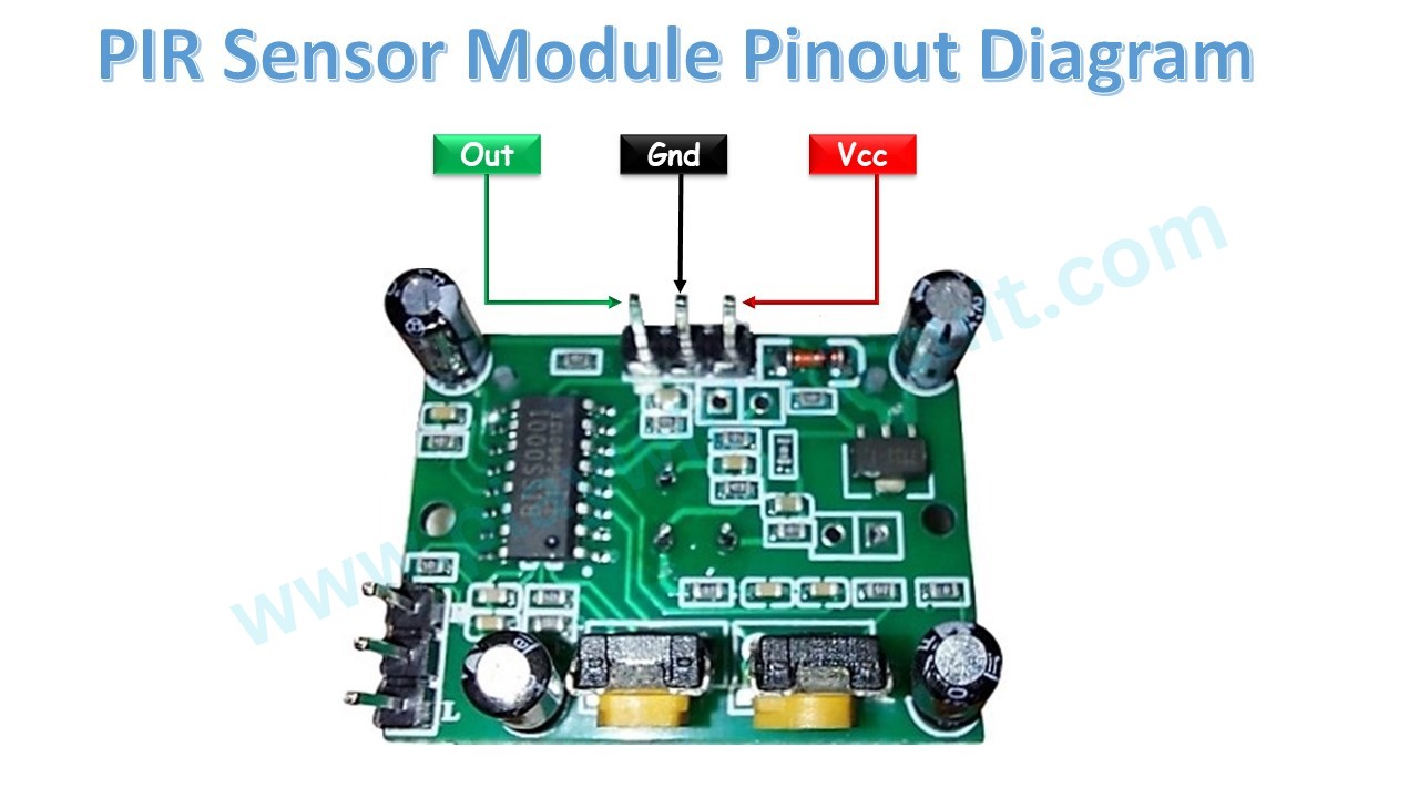
The HC-SR501 module typically has three pins for connection:
Vcc This pin is used to provide power to the sensor module. It supports input of 4.5V to 12 volts, but generally it is connected to a 5V power source.
GND This pin is the Ground pin and should be connected to the ground (0V) of the power source.
OUT This pin is the output of the sensor module. It provides a digital signal indicating the presence or absence of motion. When motion is detected, the OUT pin will go high (typically 3.3V or 5V). When motion is not detected, the OUT pin remains low (0V).
HC-SR501 PIR Sensor Module Hardware Overview
The HC-SR501 sensor consists of various components as shown below:
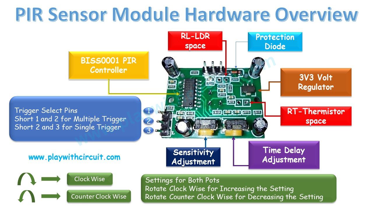
BISS0001 PIR Controller BSS0001 controller is the signal processing IC. It takes the raw data from the sensor and processes it to detect motion and provide digital output. It also amplifies and filters the signals to remove noise and interference.
RT and RL PIR motion sensor provides two solder pads for components labelled as RT and RL at the backside of the board. We can use these pads to solder thermistor and LDR to increase the adaptability of our sensor.
RL is used for soldering a light dependent resistor (LDR) or a photoresistor. Adding this allows the sensor to operate in dark places.
RT is used for soldering a thermistor or temperature sensitive resistor. Adding this will allow the sensor to be used in extreme temperatures. It also increases the accuracy of the movement detection.
Protection Diode This sensor module contains a protection diode to protect the circuit from reverse voltage and current.
3.3V Voltage Regulator This allows the PIR sensor to be used with different microcontrollers of various logic levels with ease. We can use DC voltage in between 4.5V-12V to power this sensor due to the presence of the voltage regulator.
Trigger Selection Jumper There are two trigger modes in HC-SR501 PIR sensor- Single Trigger mode and Multiple trigger mode.
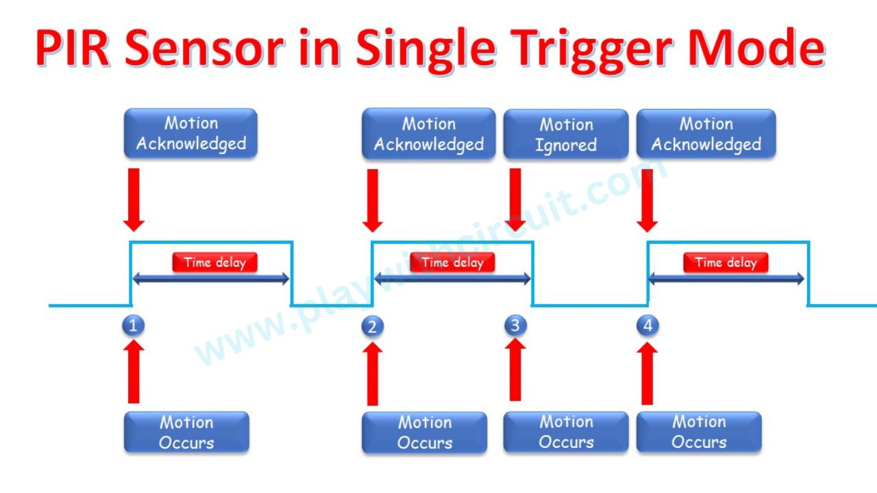
Single Trigger mode: If the jumper is positioned at Lower side, i.e., when pin 2 and pin 3 is shorted, the output signal will be HIGH, when a motion is detected. In this duration while the Output is HIGH, sensor ignores another instance of Motion. It will only trigger another HIGH Pulse at another motion instance, when previous HIGH pulse at Output Pin goes LOW.
For Example, in below image, motion occurred at time instance 1, 2 and 4 is acknowledged. But the motion Occurred at time instance 3 is ignored by sensor.
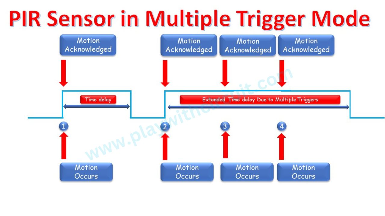
Multiple Trigger Mode: If the jumper is positioned at Higher side, i.e., when pin 1 and pin 2 is shorted, the output signal will be HIGH when a motion is detected. In this duration while the Output is HIGH, when sensor detects the next instance of motion, it resets the HIGH time of Output Pulse.
For Example, in below image motion occurred at time instance 3 is not ignored by sensor and Time delay is Extended.
Sensitivity Adjustment We can adjust the sensitivity of the sensor by rotating the potentiometer or variable resistors available on the sensor. It enables us to adjust the range (3m – 7m) for motion detection. Rotating the potentiometer clockwise increases the sensitivity and rotating it counterclockwise decreases the sensitivity.
Time-Delay Adjustment The other potentiometer on the sensor allows us to adjust the time period for which the output will remain high when motion is detected. Rotating the potentiometer clockwise increases the delay, and rotating it counter-clockwise decreases the delay.
HC-SR501 Specifications
| Operating voltage | 5V – 20V |
| Quiescent current | 50 μA |
| Level output | HIGH 3.3 V / LOW 0 V |
| Time delay | 3 – 300 s |
| Blocking time | 2.5 s (default) |
| Trigger | Single trigger / Multiple trigger |
| Detection Distance | 3 – 7 m |
| Detection angle | < 110° |
| Operating temperature | -15 – 70 °C |
| Fresnel lens dimensions | 15 mm x 23 mm diameter |
Using the HC-SR501 PIR Motion Sensor as a Standalone Unit
PIR sensor is a versatile sensor and for most applications, you can just use it as a standalone unit without any microcontroller. You can use the output signal to trigger things like LEDs and relays. With this setup, we can easily test the functionality of the sensor. You can also play around with the sensitivity, time-delay settings, and trigger modes.
Required Components
The wiring for this setup is very easy:
- Connect the VCC and GND of the sensor to a battery.
- Connect the cathode pin of a red LED to ground, and the anode pin to output through the 100 Ohm resistor.
- Now when movement is detected, the output pin goes HIGH and the LED turns ON.
Note that once you power up the circuit, wait for a few moments for the PIR sensor to adjust to the IR waves in the surrounding.
The working for this setup is shown below:
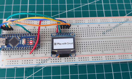
Interfacing HC-SR501 PIR Sensor to Arduino
Now let us learn how to interface the HC-SR501 PIR motion sensor with an Arduino UNO microcontroller.
Components Used
Circuit Diagram for Interfacing HC-SR501 PIR Sensor to Arduino
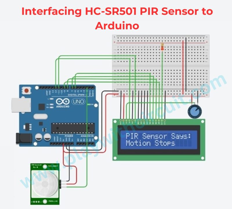
In the above wiring diagram, you can see connecting the HC-SR501 PIR sensor to the Arduino is very straight forward. The PIR sensor is powered directly from the Arduino’s 5V and GND pins, while its OUT pin is connected to digital pin 2 of the Arduino. Whenever the sensor detects motion, it drives the OUT pin HIGH, allowing the Arduino to determine whether movement is present.
A 16×2 LCD operates in 4-bit mode, reducing the number of Arduino pins required for communication. The control pins RS and E are connected to Arduino pins 12 and 11, respectively, while data pins D4–D7 are connected to pins 6, 7, 8, and 9. A 10kΩ potentiometer is connected to the VEE pin of the LCD to adjust the display contrast, and a 220Ω resistor is used to limit the current through the LCD backlight.
The connections between Arduino Uno and PIR Sensor are as follows:
| PIR Sensor | Arduino Side |
|---|---|
| Vcc | 5V Supply |
| Gnd | Ground Pin |
| OUT | Pin 2 |
The connections between Arduino Uno and LCD are as follows:
| Lcd Side Pin | Arduino Side / Bread Board Connection |
|---|---|
| VSS/GND (Pin 1) | Connected to Ground |
| VDD/VCC (pin 2) | Connected to 5V |
| VEE/Vo (Pin 3) | Connected to Variable pin of 10k POT to Control Contrast of LCD |
| RS (Pin 4) | 12 |
| R/W (pin 5) | Connected to Ground |
| E (Pin6) | 11 |
| D0 (pin 7) | Pulled to Ground, No connection with Arduino |
| D1 (pin 8) | Pulled to Ground, No connection with Arduino |
| D2 (pin 9) | Pulled to Ground, No connection with Arduino |
| D3 (pin 10) | Pulled to Ground, No connection with Arduino |
| D4 (pin 11) | 6 |
| D5 (pin 12) | 7 |
| D6 (pin 13) | 8 |
| D7 (pin 14) | 9 |
| LED(+) (Pin 15) | Connected to Vcc via 220 ohm resistor |
Arduino Code
This Arduino sketch reads the digital output of the HC-SR501 PIR sensor and displays the motion detection status on a 16×2 LCD. Whenever motion is detected, the Arduino updates the LCD with an appropriate message in real time.
/*
How to Interface HC-SR501 PIR Sensor with Arduino
by www.playwithcircuit.com
*/
#include <LiquidCrystal.h> // We are using JHD 16x2 alphanumeric LCD using HD44780 controller for its controller

LiquidCrystal lcd(12, 11, 6,7,8,9);

int sensorInput = 2;   // Output for PIR sensor input for controller
int sersorReturn=0;
void setup() {
  pinMode(sensorInput, INPUT);   // declare sensor pin as input pin
  // set up the LCD's number of columns and rows:
  lcd.begin(16, 2);
  // set the cursor to (column = 0,row = 0)
  lcd.setCursor(0, 0);
  lcd.print("PIR Sensor Says:");
  // set the cursor to (column = 0,row = 1)
  lcd.setCursor(0, 1);
}

void loop() {
  sersorReturn = digitalRead(sensorInput);  // read input value

  if(sersorReturn == HIGH)
  {
    // set the cursor to (column = 0,row = 1)
    lcd.setCursor(0, 1);
    lcd.print("Motion Occurs");
  }
  else
  {
    // set the cursor to (column = 0,row = 1)
    lcd.setCursor(0, 1);
    lcd.print("Motion Stops ");
  }
}
Simulation
Output
Explanation of Code
The code has been written to detect a Motion. This Motion is detected by PIR sensor which gives a HIGH Pulse, which is sensed by Arduino UNO and it gets Displayed on LCD.
In above code firstly header “LiquidCrystal.h” is included for using functions related to LCD. And using “LiquidCrystal” library we created object called “lcd”.
#include “LiquidCrystal.h”
LiquidCrystal lcd(12, 11, 6,7,8,9);
Here, 12th pin and 11th pin of Arduino act as R/S pin and Enable pin of LCD and R/W pin is directly connected to GND.
In this code we are using lcd in 4-bit mode i.e., we will be using D4, D5, D6, D7 data lines of lcd to display characters on it by using 6, 7, 8, 9 pins of Arduino board.
Then we define Pin2 of Arduino as sensorInput also we define one variable sersorReturn to store the state of Pin2.
int sensorInput = 2;   // Output for PIR sensor input for controller
int sersorReturn=0;
In the setup() function sensorInput pin is initialized as Input pin to Arduino and LCD is initialized for number of rows and columns using function lcd.begin(16, 2). In the later part of setup function lcd print function is used to display text on lcd using function lcd.print().
void setup() {
  pinMode(sensorInput, INPUT);     // declare sensor pin as input pin
  // set up the LCD's number of columns and rows:
  lcd.begin(16, 2);
  // set the cursor to (column = 0,row = 0)
  lcd.setCursor(0, 0);
  lcd.print("PIR Sensor Says:");
  // set the cursor to (column = 0,row = 1)
  lcd.setCursor(0, 1);
}
In the loop() function sensorInput pin is read and using function digitalRead() and its status is stored in variable sersorReturn and based on the value stored in sersorReturn LCD displays either Motion has occurred on not, using if else Logic.
void loop() {
sersorReturn = digitalRead(sensorInput); // read input value
if(sersorReturn == HIGH)
{
// set the cursor to (column = 0,row = 1)
lcd.setCursor(0, 1);
lcd.print("Motion Occurs");
}
else
{
// set the cursor to (column = 0,row = 1)
lcd.setCursor(0, 1);
lcd.print("Motion Stops ");
}
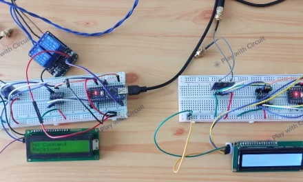
}Project Demonstration
FAQ’S
Why is PIR sensor used?
PIR sensors are widely used due to their ability to detect presence or movement of humans or animals. They work by detecting changes in infrared radiation emitted by objects within their detection range. This makes them highly suitable for applications such as security systems. They can effectively detect unauthorized entry or movement and trigger alarms or alert systems.
How do I adjust the sensitivity on my PIR sensor?
You can use the Sensitivity Adjust knob of the PIR sensor. The sensitivity adjustment knob determines the distance of motion detection of the sensor. It can be made to vary between 3 metres and 7 metres.
What is the output of PIR sensor?
A PIR sensor typically provides output high (ON) or low (OFF), indicating the presence or absence of infrared radiation emitted by objects within its detection range. When the sensor detects infrared radiation, it generates a high-level signal, indicating motion or the presence of a heat source. Conversely, when there is no infrared radiation detected, the sensor outputs a low-level signal, indicating no motion or the absence of a heat source.
What is the frequency range of PIR sensors?
The specific frequency range of PIR sensors is typically between 8 to 14 micrometers (µm), which corresponds to the wavelengths associated with the thermal radiation emitted by most common objects.
What are the advantages of PIR sensor?
- PIR sensors are energy-efficient.
- Quick detection of motion or heat sources.
- PIR sensors are generally affordable.
- PIR sensors are easy to install.
- PIR sensors have a wide detection range.

