
Liquid crystal displays (LCDs) are commonly used to display data in various devices such as calculators, microwave ovens, and others. LCD displays are available in various sizes 16×1, 16×2, 20×4, and 40×2.
These LCDs can be used to display data from the Arduino or any sensor connected to it. For example, you can create a speed detector system with Arduino which displays the speed on LCD. Depending on what you want to build, an LCD is a highly useful output device for your Arduino.
In this tutorial, we will learn about how to interface a 16×2 LCD with an Arduino UNO and how to display custom characters on the LCD. We will also look at 8-bit mode and 4-bit mode of LCD connection.
What is 16×2 LCD Module?
There are many ways to display characters, strings, numbers like serial port, GLCD, TFT displays. Among them, the most convenient, portable and easiest way is to use a 16×2 LCD display. Here we will learn about the 16×2 LCD module which uses Hitachi’s LCD controller chip, HD44780.
LCD screens consist of multiple layers, including two polarized panels with a liquid crystal solution sandwiched in between. The liquid crystals can manipulate the light passing through them when an electric current is applied. By controlling the electric current, different segments of the screen can be selectively activated or deactivated, allowing the display to create icons or text.
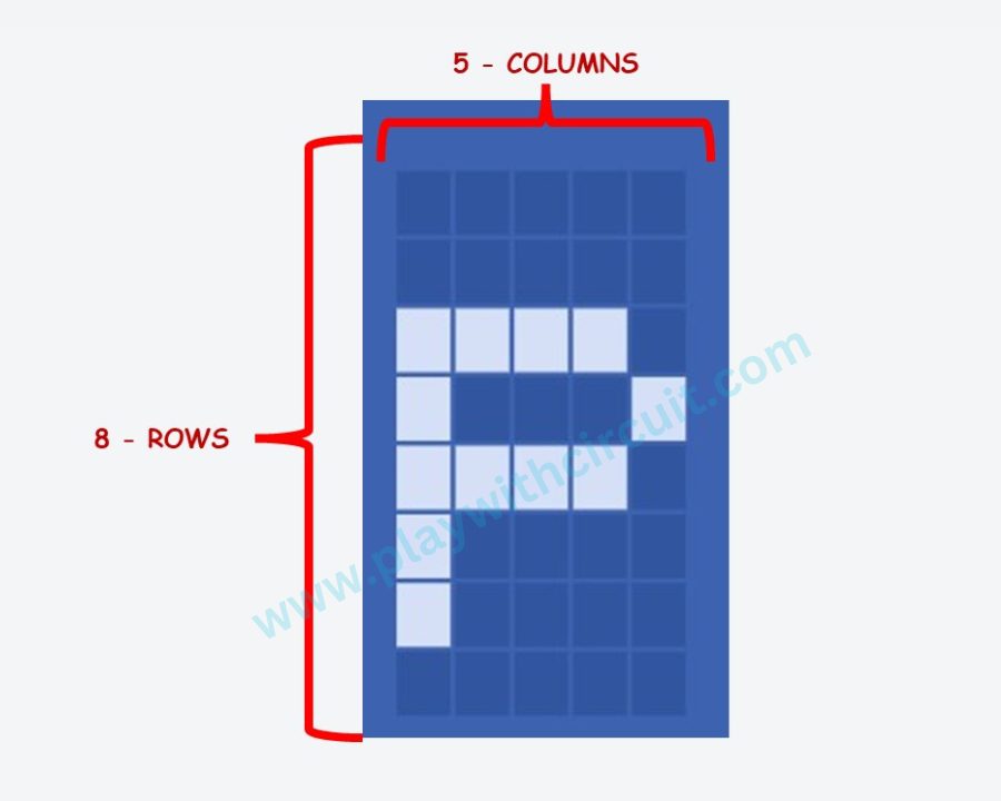
Here, we will learn to display text only on 16×2 LCD display. It consists of 16 columns numbered from 0 to 15 and 2 rows numbered as 0 and 1. There are a total of 32 locations to display characters and each Location is made up of 5×8 pixel grid (5 Columns and 8 Rows) which are used to display 1 character.
Hence any character which can be displayed on this LCD is a combination of turning ON/OFF of 40 pixels in the Grid.
16×2 LCD pinout Diagram
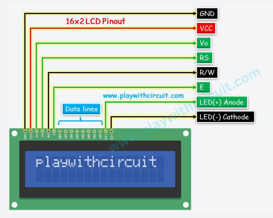
GND This pin should be connected to ground.
Vcc It is the power supply pin, typically it should be connected to 5V.
Vo It is used to control the LCD contrast. A 10k pot could be used to control the voltage at this pin as a voltage divider.
RS (Register Select) It is used to separate LCD commands from LCD data. Before sending command to LCD data pins, set RS pin LOW and Before sending data to LCD, set RS pin HIGH.
When RS = 0, Command Register got selected inside LCD to get command and when RS = 1 Data Register got selected inside LCD to Get data.
R/W(Read/Write) When user want to Write data to LCD, R/W pin is set to LOW and when user want to Read data from LCD, R/W pin is set to HIGH. When user want to check busy status of LCD (using D7 data bit) only then R/W pin should be HIGH, else it should always be LOW.
Enable It is used to Latch data present on data pin D0 to D7. After setting the data bits at data pins. A HIGH to LOW pulse must be sent to latch in the data present at data pin. The pin must be kept high for at-least 450 ns. To read the D7 bit in read mode, LOW to HIGH pulse should be sent at this pin.
D0 to D7(Data pins) This 8-bit data bus is used to write command/data to LCD.
Pull RS pin LOW and R/W pin to LOW and then send the command to LCD pins.
Pull RS pin HIGH and R/W pin to LOW and then send the data in ASCII format. e.g., if user want to display ‘A’ set RS = 1, R/W= 0 and send data 0x41.
We can also read busy flag by checking D7 bit. But before that RS should be pulled to LOW and R/W pin to HIGH and then read D7 bit to check if LCD is busy. D7 is pulled to HIGH by LCD as long as it is busy with its internal operations. When LCD is free D7 is pulled LOW.
When LCD works in 8-bit mode all the pins should be connected to microcontroller.
When LCD works in 4-bit mode D4 to D7 bits are used to send the data/command to LCD and D0 to D3 should be pulled to GND.
LED (+) (Anode) It should be connected to 5 V via 220 ohm resistor. It controls the LED backlight. By connecting the POT as voltage divider at this PIN the brightness of LCD can be controlled.
LED (-) (Cathode) It should be connected to Ground.
Difference between Command and Data Register
Command Register
It stores commands sent to LCD. When RS = 0 command register gets selected inside LCD to receive Data-Byte provided on data bus. A command is an instruction given to LCD to do a particular task.
e.g., Clear Display, Return Home, Shift Display right, Shift Display Left
Data Register
It stores data sent to LCD. When RS = 1 data register gets selected inside the LCD to receive Data provided on the data bus and after receiving data it is processed to display it on LCD. The data can be ASCII code of alphabets(A-Z, a-z), numbers(0-9) and selected symbols.
Interfacing LCD with Arduino in 8-bit mode
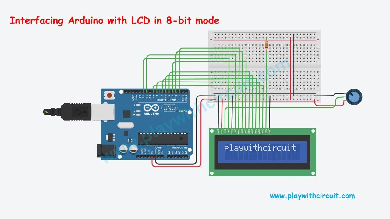
In the interfacing diagram, we can see an Arduino UNO is connected to a 16×2 LCD using a breadboard. A 10k pot is also connected to control voltage at Vo (contrast pin).
Here we will learn about Arduino code which will be burned on Arduino controller to run 16×2 LCD in 8-bit mode. In this mode All the data lines will be used for communications. Also we do not check the ready bit (pin D7), instead a delay will be provided after every command. Hence R/W pin is permanently connected to Ground.
Components Used
The Connection between Arduino Uno and LCD is as follows:
| Lcd Side Pin | Arduino Side/ Bread Board Connection |
|---|---|
| VSS/GND (Pin 1) | Connected to Ground |
| VDD/VCC (pin 2) | Connected to 5V |
| VEE/Vo (Pin 3) | Connected to Variable pin of 10k POT to Control Contrast of LCD |
| RS (Pin 4) | 12 |
| R/W (pin 5) | Connected to Ground |
| E (Pin6) | 11 |
| D0 (pin 7) | 2 |
| D1 (pin 8) | 3 |
| D2 (pin 9) | 4 |
| D3 (pin 10) | 5 |
| D4 (pin 11) | 6 |
| D5 (pin 12) | 7 |
| D6 (pin 13) | 8 |
| D7 (pin 14) | 9 |
| LED(+)(Pin 15) | Connected to Vcc via 220 ohm resistor |
| LED(-)(Pin 16) | Connected to Ground |
Adding Library for Arduino Code
Before writing code in Arduino IDE, we must install LCD library.
Steps to install LCD library in Arduino IDE.
- Open Arduino IDE and create a new “.ino” file lcd_8_bit_mode.ino.
- Go to Library Manager and search lcd.
- Now Install “LiquidCrystal” library by Arduino, Adafruit.
Arduino Code
/*
Interfacing LCD with Arduino in 8-bit mode
by www.playwithcircuit.com
*/
#include <LiquidCrystal.h>
// We are using JHD 16x2 alphanumeric LCD using HD44780 controller for its controller
// initialize the library with the numbers of the interface pins
// Here We initlialize LCD in 4 bit mode when R/W pin (Pin 5 of LCD) is permanently attached to GND
// LCD side / Arduino Side Pin
// (Pin 4 )RS = 12
// (Pin 6 )E = 11
// (Pin 7 )D0 = 2
// (Pin 8 )D1 = 3
// (Pin 9 )D2 = 4
// (Pin 10)D3 = 5
// (Pin 11)D4 = 6
// (Pin 12)D5 = 7
// (Pin 13)D6 = 8
// (Pin 14)D7 = 9
// Pin No 1 and 16 of LCD of should be connected to GND
// Pin No 2 and 15 of LCD of should be connected to VCC
// A 10k pot should be connected b/w VCC and GND and its variable o/p pin shpuld be connected to VEE (pin 3 of LCD) to control contrast of LCD.
LiquidCrystal lcd(12, 11, 2,3,4,5,6,7,8,9);
void setup() {
// set up the LCD's number of columns and rows:
lcd.begin(16, 2);
}
void loop() {
// set the cursor to (column = 0,row = 0)
lcd.setCursor(0, 0);
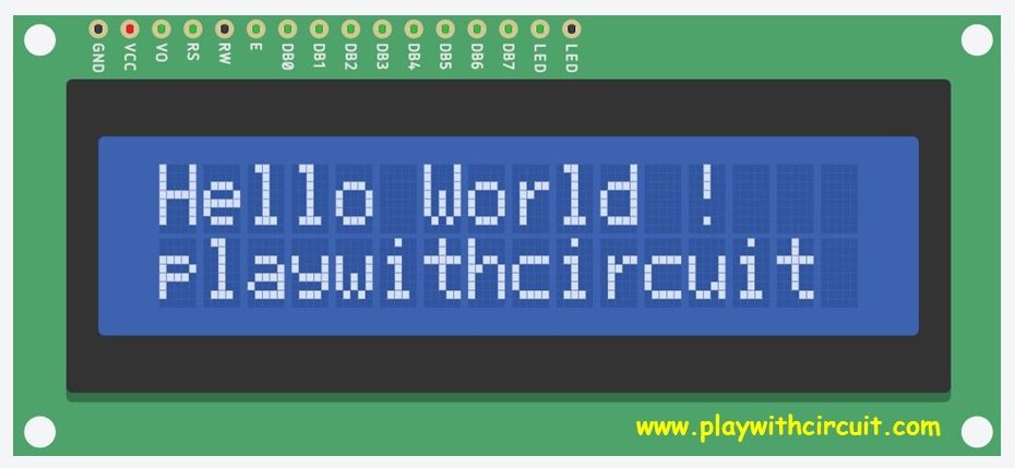
lcd.print("Hello World !");
// set the cursor to (column = 0,row = 1)
lcd.setCursor(0, 1);
lcd.print("playwithcircuit");
while(1);
}The Output of Code
Explanation of the Code
In above code firstly header “LiquidCrystal.h” is included for using functions related to LCD. And using “LiquidCrystal” library we created object called “lcd”.
#include “LiquidCrystal.h”
LiquidCrystal lcd(12, 11, 2, 3, 4, 5, 6, 7, 8, 9);
Here 12th pin and 11th pin of Arduino acts as R/S pin and Enable pin of LCD and R/W pin is directly connected to GND.
In this code we are using lcd in 8-bit mode i.e., we will be using D0, D1, D2, D3, D4, D5, D6, D7 data lines of lcd to display characters on it by using 2, 3, 4, 5, 6, 7, 8, 9 pins of Arduino board.
In the setup() function we use lcd.begin(), for providing number of columns and rows.
void setup() {
  // set up the LCD's number of columns and rows:
  lcd.begin(16, 2);
}
In the loop() function firstly lcd cursor is set to position column 0 and row 0 using function lcd.setCursor() and then then print “Hello World !” on the lcd using function lcd.print().
After that cursor location is further changed to column 0 and row 1. And then “playwithcircuit” is printed on lcd using function lcd.print(). At the end of loop() function the code is paused using infinite while loop by adding while(1).
Everything Discussed above is realized by using below code:
void loop() {
   // set the cursor to (column = 0,row = 0)
 lcd.setCursor(0, 0);
 lcd.print("Hello World !");
  // set the cursor to (column = 0,row = 1)
 lcd.setCursor(0, 1);
 lcd.print("playwithcircuit");
 while(1);
}
💡Must Read

Interfacing I2C LCD with Arduino Uno
This article explains how to interface I2C LCD with an Arduino UNO and print text, custom characters and numbers on it.
Interfacing LCD with Arduino in 4-bit mode
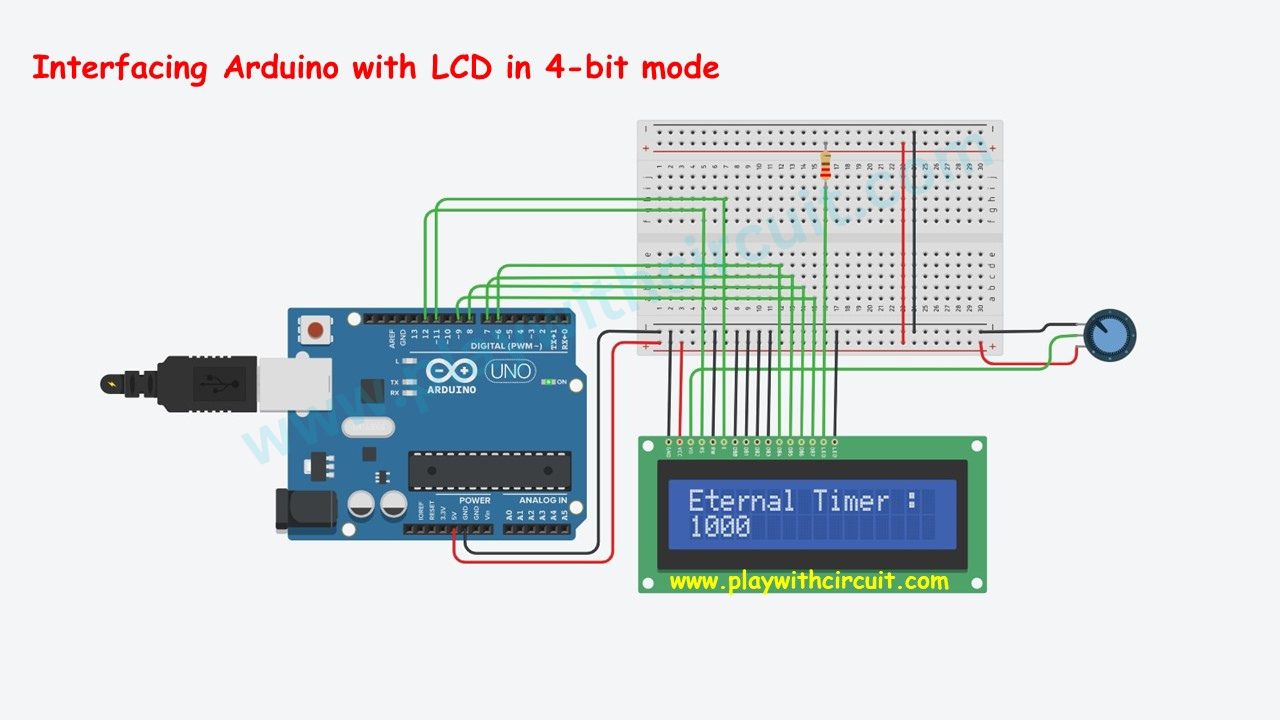
In the interfacing diagram, we can see an Arduino UNO is connected to a 16×2 LCD using a breadboard. A 10k pot is also connected to control voltage at Vo (contrast pin).
In this section, we will learn about Arduino code which will be burned on Arduino controller to run 16×2 LCD in 4-bit mode. In this mode all the data lines will not be used for communication only D4, D5, D6 and D7 data lines of LCD will be used. Also we not be check ready bit (pin D7), instead a delay will be provided after every command. Hence R/W pin is permanently connected to Ground. Also, D0 to D3 will not be used hence they will also be pulled to Ground. Also install the same Arduino Library for LCD as described above.
Components Used
| Component Name | Quantity | Remarks |
|---|---|---|
| Arduino UNO R3 | 1 | Revision R3 |
| LCD | 1 | 16 x 2 |
| Potentiometer | 1 | 10 kΩ |
| Resistor | 1 | 220 Ω |
| Breadboard | 1 | Full Size |
The Connection between Arduino Uno and LCD is as follows:
| Lcd Side Pin | Arduino Side/ Bread Board Connection |
|---|---|
| VSS/GND (Pin 1) | Connected to Ground |
| VDD/VCC (pin 2) | Connected to 5V |
| VEE/Vo (Pin 3) | Connected to Variable pin of 10k POT to Control Contrast of LCD |
| RS (Pin 4) | 12 |
| R/W (pin 5) | Connected to Ground |
| E (Pin6) | 11 |
| D0 (pin 7) | Pulled to Ground, No connection with Arduino |
| D1 (pin 8) | Pulled to Ground, No connection with Arduino |
| D2 (pin 9) | Pulled to Ground, No connection with Arduino |
| D3 (pin 10) | Pulled to Ground, No connection with Arduino |
| D4 (pin 11) | 6 |
| D5 (pin 12) | 7 |
| D6 (pin 13) | 8 |
| D7 (pin 14) | 9 |
| LED(+)(Pin 15) | Connected to Vcc via 220 ohm resistor |
| LED(-)(Pin 16) | Connected to Ground |
Arduino code
/*
Interfacing LCD with Arduino in 4-bit mode
by www.playwithcircuit.com
*/
#include <LiquidCrystal.h> // We are using JHD 16x2 alphanumeric LCD using HD44780 controller for its controller
// initialize the library with the numbers of the interface pins
// Here We initialize LCD in 4-bit mode when R/W pin (Pin 5 of LCD) is permanently attached to GND
// LCD side   / Arduino Side Pin
// (Pin 4 )RS = 12
// (Pin 6 )E  = 11
// (Pin 7 )D0 (pulled to GND) = No connection with Arduino
// (Pin 8 )D1 (pulled to GND) = No connection with Arduino
// (Pin 9 )D2 (pulled to GND) = No connection with Arduino
// (Pin 10)D3 (pulled to GND) = No connection with Arduino
// (Pin 11)D4 = 6
// (Pin 12)D5 = 7
// (Pin 13)D6 = 8
// (Pin 14)D7 = 9
// Pin No 1 and 16 of LCD of should be connected to GND
// Pin No 2 and 15 of LCD of should be connected to VCC
// A 10k pot should be connected b/w VCC and GND and its variable o/p pin shpuld be connected to VEE (pin 3 of LCD) to control contrast of LCD.

LiquidCrystal lcd(12, 11, 6, 7, 8, 9);

void setup() {
 // set up the LCD's number of columns and rows:
 lcd.begin(16, 2);
 // set the cursor to (column = 0,row = 0)
 lcd.setCursor(0, 0);
 lcd.print("Eternal Timer :");
}

void loop() {
 // set the cursor to (column = 0,row = 1)
 lcd.setCursor(0, 1);
 lcd.print(millis());
}
The Output of Code
Explanation of the Code
This code is written to print eternal counter in millisecond on second row of LCD.
In above code firstly header “LiquidCrystal.h” is included for using functions related to LCD. And using “LiquidCrystal” library we created object called “lcd”.
#include “LiquidCrystal.h”
LiquidCrystal lcd(12, 11, 6,7,8,9);
Here 12th pin and 11th pin of Arduino acts as R/S pin and Enable pin of LCD and R/W pin is directly connected to GND.
In this code we are using lcd in 4-bit mode i.e., we will be using D4, D5, D6, D7 data lines of lcd to display characters on it by using 6, 7, 8, 9 pins of Arduino board.
In the setup() function we use lcd.begin(), for providing number of columns and rows. After that cursor location is further changed to column 0 and row 0. And then “Eternal Timer” is printed on lcd using function lcd.print().
void setup() {
 // set up the LCD's number of columns and rows:
 lcd.begin(16, 2);
 // set the cursor to (column = 0,row = 0)
 lcd.setCursor(0, 0);
 lcd.print("Eternal Timer :");
}
In the loop() function firstly lcd cursor is set to position column 0 and row 1 using function lcd.setCursor() and then then print milli seconds on the lcd using function lcd.print() and millis().
Now the program will always remain in loop() as this is an infinite looping function.
void loop() {
 // set the cursor to (column = 0,row = 1)
 lcd.setCursor(0, 1);
 lcd.print(millis());
}
Display Custom Character on LCD
Hitachi HD44780 driver-based LCD provides us the facility to display self-made characters and icons on the LCD. But unlike characters stored in CGROM, they need to be stored in CGRAM and then displayed on the LCD.
What is CGROM?
CGROM stands for Character Generation Read Only Memory. It is a memory inside the LCD which saves the display pattern of every character and symbol in form of 8 bytes. For example in the picture displayed here we can see display pattern on character ‘p’. This pattern is stored permanently inside CGROM. When user want to display this character. The ASCII value of letter ‘p’ is sent to the LCD and it is stored in current DDRAM address of LCD and thereby it is displayed on LCD.
What is DDRAM?
DDRAM stands for Data Display Random Access Memory. It saves the pattern of the character temporarily. As the LCD needs to be regularly, there is some memory which saves the pattern of character this memory is known as DDRAM. The data is store in DDRAM till the power is ON.
What is CGRAM?
CGRAM stands for Character Generation Random Access Memory. The custom character or user defined characters first needs to be stored in CGRAM. Then then the address of CGRAM needs to be sent to the DDRAM. We can store maximum of 64 bytes at 8 locations in CGRAM. It means at one location we can store max 8 bytes.
How is Custom Character Made?
Making custom character for 16×2 LCD is very easy and anyone can do it. Let’s make a smiley Face on the LCD.
Steps to make Smiley:
- First make 5 columns and 8 rows blank grid.
- Fill the box which make the Smiley.
- Now write 1 on filled boxes and 0 on the blank boxes.
- Make an array smiley using 8 bytes created.
Arduino Code
/*
Display Custom Character on LCD
by www.playwithcircuit.com
*/
#include <LiquidCrystal.h> // We are using JHD 16x2 alphanumeric LCD using HD44780 controller for its controller

// initialize the library with the numbers of the interface pins
// Here We initialize LCD in 4-bit mode when R/W pin (Pin 5 of LCD) is permanently attached to GND
// LCD side   / Arduino Side Pin
// (Pin 4 )RS = 12
// (Pin 6 )E  = 11
// (Pin 7 )D0 (pulled to GND) = No connection with Arduino
// (Pin 8 )D1 (pulled to GND) = No connection with Arduino
// (Pin 9 )D2 (pulled to GND) = No connection with Arduino
// (Pin 10)D3 (pulled to GND) = No connection with Arduino
// (Pin 11)D4 =  6
// (Pin 12)D5 =  7
// (Pin 13)D6 =  8
// (Pin 14)D7 =  9
// Pin No 1 and 16 of LCD of should be connected to GND
// Pin No 2 and 15 of LCD of should be connected to VCC
// A 10k pot should be connected b/w VCC and GND and its variable o/p pin shpuld be connected to VEE (pin 3 of LCD) to control contrast of LCD.

LiquidCrystal lcd(12, 11, 6,7,8,9);
char u8Buffer[17]="Smile ArmUp Face";

byte smiley[8] = {
  0b00000,
  0b00000,
  0b01010,
  0b00000,
  0b00000,
  0b10001,
  0b01110,
  0b00000
};

byte armsUp[8] = {
  0b00100,
  0b01010,
  0b00100,
  0b10101,
  0b01110,
  0b00100,
  0b00100,
  0b01010
};

byte face[8] = {
  0b11111,
  0b10001,
  0b00000,
  0b01010,
  0b00000,
  0b00100,
  0b00000,
  0b01110
};

void setup() {
  // initialize LCD and set up the number of columns and rows:
  lcd.begin(16, 2);
}

void loop() {
  // create a new character
  lcd.createChar(0, smiley);
   // create a new character
  lcd.createChar(1, armsUp);
  // create a new character
  lcd.createChar(2, face);

  // set the cursor to the top left
  lcd.setCursor(0, 0);
  lcd.write(byte(0)); // when calling lcd.write() '0' must be cast as a byte , for zeroth loaction

  delay(300);
  // set the cursor to the top left
  lcd.setCursor(7, 0);
  lcd.write(byte(1)); // when calling lcd.write() '1' must be cast as a byte , for first loaction

  delay(300);
  // set the cursor to the top left
  lcd.setCursor(15, 0);
  lcd.write(2);       // when calling lcd.write() pass 2 , for second location

  delay(300);
  lcd.setCursor(0, 1);
  for(int i=0; i < 17; i++){
    lcd.print(u8Buffer[i]);
    delay(100);
  }
  while(1);
}
Output of the Code
Explanation of Code
In the above Arduino Code, we will be making and displaying three custom characters.
Firstly header “LiquidCrystal.h” is included for using functions related to LCD. And using “LiquidCrystal” library we created object called “lcd”.
#include <LiquidCrystal.h> // We are using JHD 16x2 alphanumeric LCD using HD44780 controller for its controller
LiquidCrystal lcd(12, 11, 6,7,8,9);
Here, 12th pin and 11th pin of Arduino acts as R/S pin and Enable pin of LCD and R/W pin is directly connected to GND.
In this code we are using lcd in 4-bit mode i.e., we will be using D4, D5, D6, D7 data lines of lcd to display characters on it by using 6, 7, 8, 9 pins of Arduino board.
Now make a character buffer to store the string “Smile ArmUp Face” and then make array for three custom character arrays each consists of 8-bytes.
char u8Buffer[17]="Smile ArmUp Face";

byte smiley[8] = {
  0b00000,
  0b00000,
  0b01010,
  0b00000,
  0b00000,
  0b10001,
  0b01110,
  0b00000
};

byte armsUp[8] = {
  0b00100,
  0b01010,
  0b00100,
  0b10101,
  0b01110,
  0b00100,
  0b00100,
  0b01010
};

byte face[8] = {
  0b11111,
  0b10001,
  0b00000,
  0b01010,
  0b00000,
  0b00100,
  0b00000,
  0b01110
};
In the setup() function we use lcd.begin(), for providing number of columns and rows. After that cursor location is further changed to column 0 and row 0.
void setup() {
  // initialize LCD and set up the number of columns and rows:
  lcd.begin(16, 2);
}
In the loop() function firstly three custom character are created in CGRAM using function lcd.createChar() And then they are displayed using function lcd.write().
In between the custom character display, delay of 300 milliseconds is given using delay() function. This function takes entry in number of milliseconds.
After all the custom characters are displayed string “Smile ArmUp Face” is displayed on second line of LCD. Now the program will always remain in loop() as this is an infinite looping function and code remain paused at the end of loop function due to while(1).
void loop() {
  // create a new character
  lcd.createChar(0, smiley);
   // create a new character
  lcd.createChar(1, armsUp);
  // create a new character
  lcd.createChar(2, face);

  // set the cursor to the top left
  lcd.setCursor(0, 0);
  lcd.write(byte(0)); // when calling lcd.write() '0' must be cast as a byte , for zeroth location

  delay(300);
  // set the cursor to the top left
  lcd.setCursor(7, 0);
  lcd.write(byte(1)); // when calling lcd.write() '1' must be cast as a byte , for first location

  delay(300);
  // set the cursor to the top left
  lcd.setCursor(15, 0);
  lcd.write(2);       // when calling lcd.write() pass 2 , for second location

  delay(300);
  lcd.setCursor(0, 1);*
  for(int i=0; i < 17; i++){
    lcd.print(u8Buffer[i]);
    delay(100);
  }
  while(1);

}
FAQ’S
Why is LCD important in Arduino?
Liquid Crystal Displays (LCDs) hold significance in the Arduino projects due to their ability to provide visual feedback, making them indispensable for conveying information in a user-friendly manner.
How many characters does a 16x2 LCD can have?
A 16×2 LCD display has 16 columns and 2 rows and each line can display 16 characters. So it can show a total of 32 characters at the same time.
What is the custom character limit for Arduino LCD?
The Arduino LCD library typically supports up to 8 custom characters, each defined by a 5×8 pixel pattern.
How to check if my 16x2 LCD is working?
To check if your 16×2 LCD is working, ensure correct wiring, adjust contrast using the potentiometer, confirm proper power supply, and upload a simple test code to display text.
