
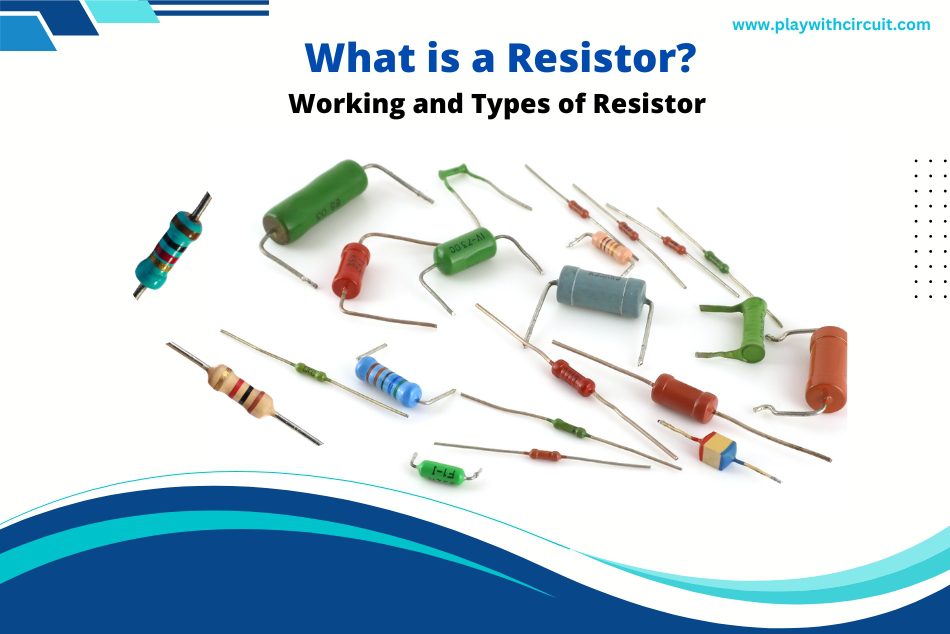
Resistors are the basic electronic components and used in just about every electronic circuit. They play a vital role in circuit designing. In this article, we will explore what a resistor is, how it works, its colour code, the different types of resistors, and their applications.
What is a Resistor?
Resistor is a passive electronic component having two terminals that creates resistance in the flow of electric current. They are primarily used for limiting or regulating the current flow and to lower the voltage in any particular portion of electronic circuits. They are also used in various other applications such as timing sources and heating elements.
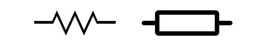
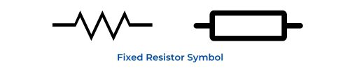
The symbol commonly used in schematic is shown below:
Resistor Unit
The resistance is measured in ohms (Ω). One ohm is the resistance between two points when a current of 1 ampere (A) passes through a resistor with a 1 volt (V) drop across its terminals. The current is proportional to the voltage across the terminals of the resistor.
This ratio is represented by Ohm’s law: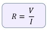
How do Resistors work?
In electronic circuits, we often need to introduce precise amounts of resistance to control the flow of current. So by adding resistance into a circuit, you can reduce the amount of current as required.
The resistive material determines the resistance value of the resistor. The resistive materials can be a mixture of carbon particles along with binder material, metal alloys, metal oxide films.
Some resistors are made of copper wires which are coiled around a ceramic rod and the outer part of the resistor is coated with an insulating paint. The resistance depends on the number of copper turns, type of material used and length of wire. If copper wire is longer, thinner and copper turns are more, the resistance will be higher as it’s difficult for electrons to pass through it.
Relationship between resistance and the size and type of material from which a resistor is made can be defined by following equation:
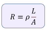
Where,
- R is the resistance
- ρ is the resistivity of the material in Ω.m which is the measure of the ability of a material to oppose the flow of current
- L is the length of a piece of material in m
- A is the cross-sectional area of the material in m2
It is evident from the above equation that the resistance (R) of a material increases as its length increases and increases as its area decreases.
Let us consider an example to understand how we can regulate current using resistor:
Dependency of Current on Resistance when Voltage is Same
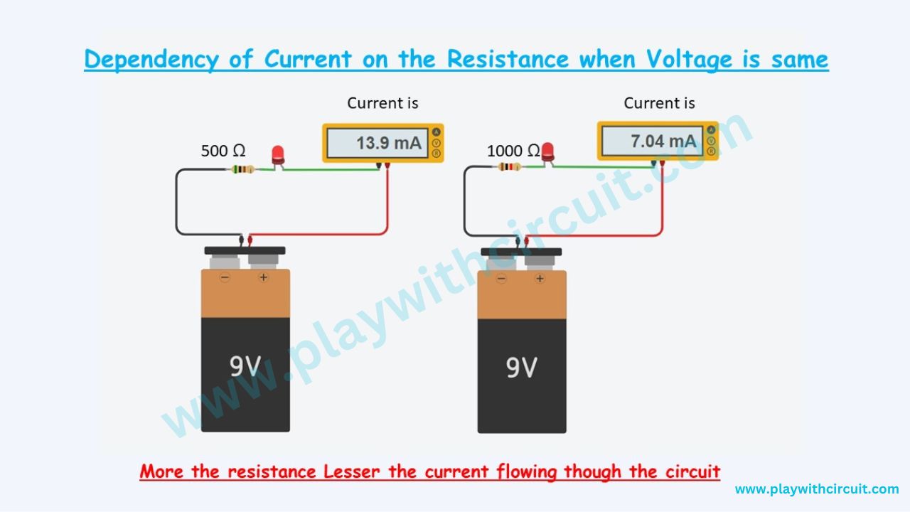
In the above picture we can see two circuits in which there is a resistance and LED connected to a 9 V battery. An Ammeter (to measure the current) is also connected in series along with LED and resistance to measure the current. First circuit resistance is 500 ohms and the current flowing in the circuit is 13.9 mA. Similarly in the second circuit resistance is 1000 ohms and the current flowing in the circuit is 7.03 mA. Hence it can be concluded that the current flowing inside the circuit is inversely proportional to the resistance i.e., as the resistance in the circuit increases current decreases.
Hence it can be concluded that I ∝ 1/R.
Dependency of Current on Voltage when Resistance is Same
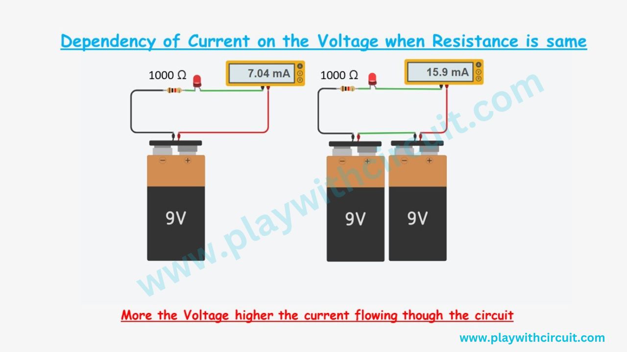
In the above picture we can see two circuits in which there is a resistance and LED connected to battery. In the first circuit 9 V battery is connected, in the second circuit two 9v batteries are connected to make the effective voltage 18 Volts. There is an Ammeter (to measure the current) is also connected in series along with LED and resistance to measure the current. In the first circuit voltage applied is 9 V and the current flowing in the circuit is 7.04 mA. Similarly in the second circuit voltage applied is 18V and the current flowing in the circuit is 15.9 mA. Hence its can be concluded that the current flowing inside the circuit is directly proportional to the voltage applied i.e., as the voltage applied in the circuit increases, current increases.
Hence it can be concluded that I ∝ V.
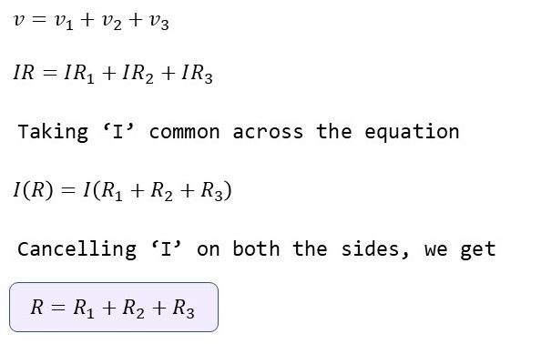
Finally, it is derived that

Resistors in Series
Resistors are said to be in series when they are connected in a single line and the current flowing through all the resistors is the same. The overall resistance of the circuit is equal to the sum of individual resistance values.
Let us consider an example:
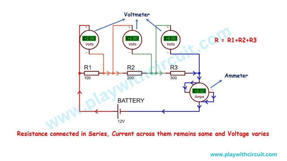
In the above circuit resistance R1(100 Ω), R2(200 Ω) and R3 (300 Ω) are connected in series. 12 V battery is connected across them.
The battery Voltage 12 V is divided across each resistance; larger the resistance, higher the voltage drop occurs across it. Hence voltage across R1 is 2 V, voltage across R2 is 4 V and voltage across R3 is 6 V.
The voltage across each resistance is measured using voltmeter across each of them.
The path of current is only one hence the same current flows across each of the resistance and we have to find the current.
Hence current across

= 0.02 A = 20 mA
Hence current across

= 0.02 A = 20 mA
Hence current across

= 0.02 A = 20 mA
When resistance is connected in series the effective resistance is the sum of individual resistance. Hence
R = R1+R2+R3
Final Resistance (R) = 100 Ω + 200 Ω + 300 Ω = 600 Ω
Voltage(V) = 12 V,

= 0.02 A = 20 mA
It’s the same current as calculated above across individual resistance.
Also, it’s the same current measures using the Ammeter in the circuit.
V = V1+V2+V3 = 2 V+4 V+6 V = 12 V
which is the equal to the voltage provided by the battery.
Resistors in Parallel
Resistors are said to be in parallel when the terminals of resistors are connected to the same two nodes. Resistors in parallel have the same voltage at their two terminals. Since there are multiple paths for the current to flow through, the current may not be the same through all the resistors.
In a parallel circuit the total current in the circuit is equal to the addition of current across each resistance.
Hence, Total current I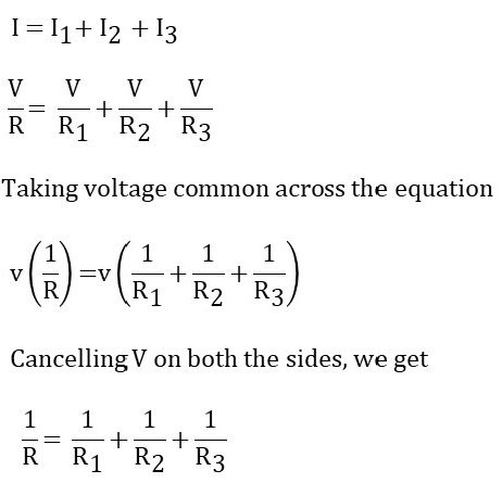
Let us consider an example:
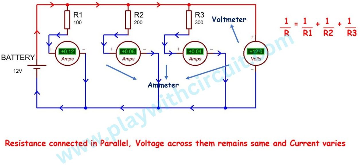
In the above circuit resistance R1(100 Ω), R2(200 Ω) and R3 (300 Ω) are connected in parallel. A 12 V battery is connected across them.
The battery voltage 12 V is same across each resistance. It is confirmed using voltmeters connected in parallel.
There are three paths of current first is across R1 second across R2 and third across R3. Since the resistance value of these resistance is different hence the current flowing across them would be different.

= 0.12 Ampere = 120 mA

= 0.06 Ampere = 60 mA

= 0.04 Ampere = 40 mA
The current calculated here is also confirmed using the Ammeter connected in series with each resistance in the above picture.
Total Current(I) = I1+I2+I3 = 120 + 60 + 40 = 220 mA
When resistance is connected in parallel then the effective resistance is the sum of reciprocals of individual resistance. Also, the effective resistance will be less than the minimum resistance. Hence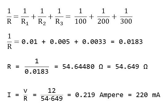
We can see that current values calculated above and with the formula is same.
What is Colour Coding of Resistors?
Resistor colour codes represent the resistance value and tolerance of a resistor. The colour bands are printed on the body of the resistor and provide a visual indication of its wattage rating. Each colour represents a specific number or value. The most common resistor colour code system consists of four or five bands.
For a four-band colour coded resistor, the first two bands represent the 1st and 2nd significant digit.
The 3rd band represents the decimal multiplier which tells you how many powers of ten to multiply by the first two numbers.
The 4th band represents the tolerance and it tells you how accurate the resistance value is likely to be.
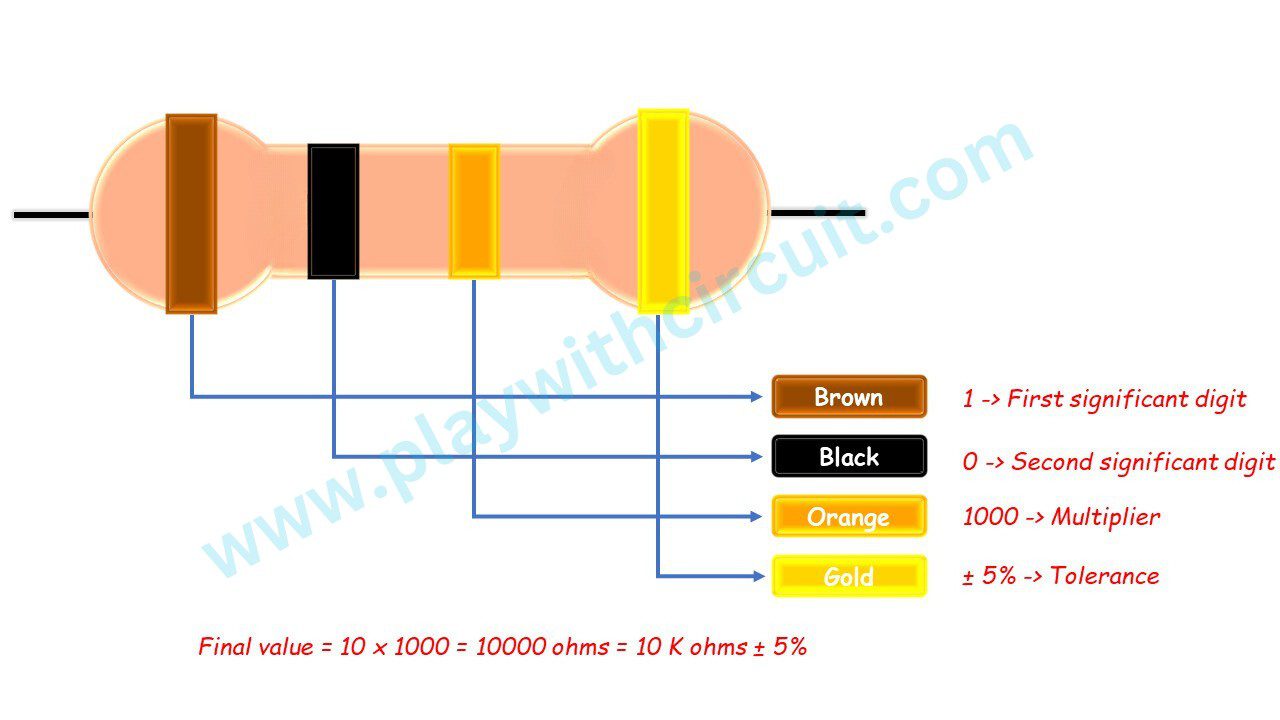
Suppose you have a resistor like the one shown above, with coloured bands that are brown, black, and orange and a fourth golden band. As you can see from the colour chart below, brown means 1 and black means 0, so the resistance is going to start with “10” and orange means 3 so we have to multiply the first two digits by 1000. So the resistance value is 10,000 ohms or 10 kΩ. The Last band is gold, it means the resistance is accurate to within plus or minus 5 percent. So in practice, the real resistance is likely to be anywhere between 9.5 kΩ and 10.5 kΩ.
If there are five bands, the first three bands give the first 3 significant digits of the resistance, the fourth band is the decimal multiplier, and the last band is the tolerance. Here’s an example of five band resistor.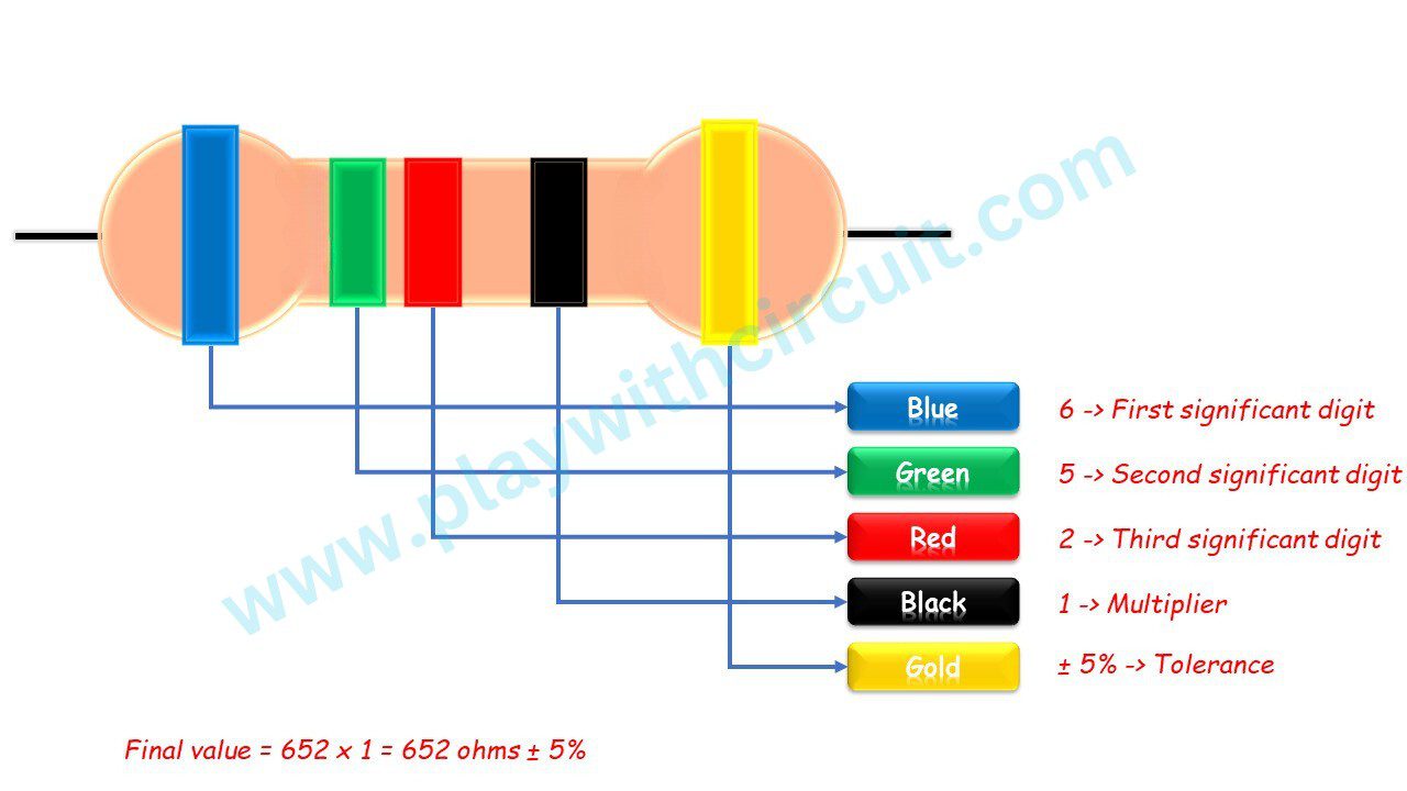
Five-band resistors are more accurate than four-band resistors, so they have a lower tolerance value.
The Resistor Colour Code Table
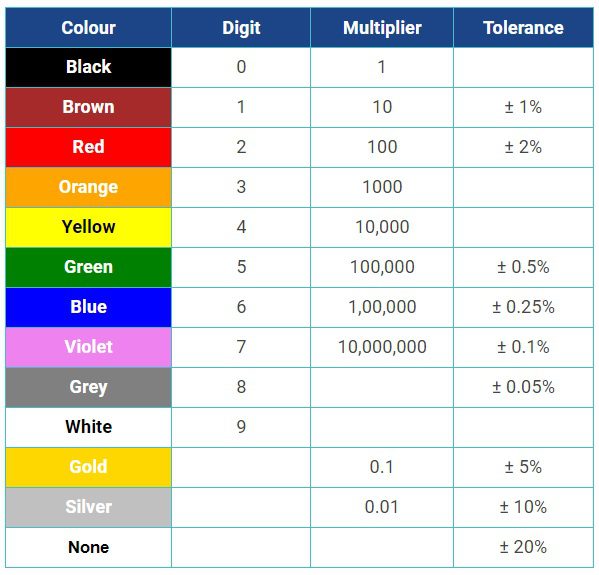
Note* You can remember the table by this saying
Better Be Right Or Your Great Big Venture Goes Wrong
B B R O Y Great Britain Very Good Wife
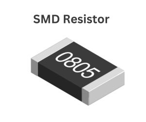
SMD Resistors
SMD or Surface Mounted Device is designed to be used with SMT, or Surface Mount Technology. In this technology smaller components are used in PCBs to be faster, more efficient, and cheaper. SMD resistors are smaller than their traditional through-hole counterparts. Instead of wires, they have small leads or pins that are soldered to pads on the surface of the board which eliminates the need for holes in the board.
As SMD resistors are small in size, there is often no room for the traditional colour band code to be printed on them. Thus, new resistor SMD codes were created: the three and four digit system and an Electronic Industries Alliance (EIA) system called EIA-96.
The Three and Four Digit Systems
In the Three-digit system, the resistance value of a resistor is represented by the first two digits, and the final digit indicates the multiplier. For example,
- 560 = 56 Ω x 10^0 = 56 Ω
- 143 = 14 Ω x 10^3 is 14,000 Ω (14 kΩ)
In the Four-digit system, the resistance value of a resistor is represented by the first three digits, and the final digit indicates the multiplier. For example,
- 1561 = 156Ω x 10^1 is 1,560 Ω (1.56 kΩ)
- 6552 = 655 Ω x 10^2 is 65,500 Ω (65.5 kΩ)
Note* Resistances of less than 100 ohms are marked with the letter ‘R’, indicating the position of the decimal point.
The EIA-96 System
The EIA-96 marking system is a more compact marking for SMD resistors. This new system was developed due to the need of higher precision resistors and decreasing sizes of resistors. It is based on the E96-series, and intended for resistors with 1% tolerance.
In this system, the marking is of three digits out of which first 2 numbers represent a code indicating the resistor value with three significant digits and 1 letter for the multiplier.
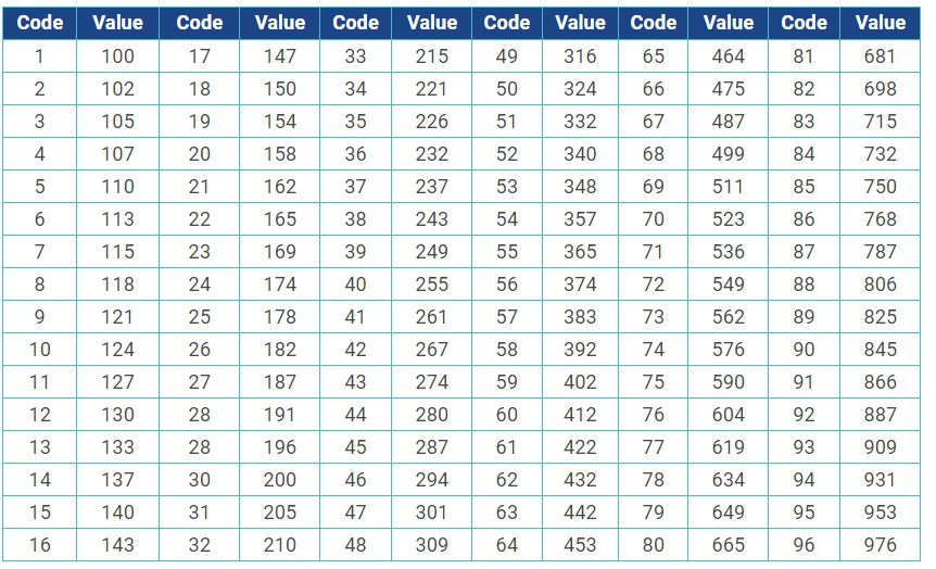
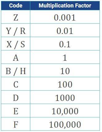
The first table below provides the resistance values corresponding to each code, and the second table below provides the multiplying factor for each letter code that gives the final value of the resistor. For example, 50E = Code 50 with Multiplier E = 324 x 10000 = 3240 K Ω ±1%

Resistor Colour Code for SMD Resistor
SMD Resistor Multiplication Factors
Resistor Power Rating
When a current passes through a resistor due to the presence of a voltage across it, energy is dissipated by the resistor in the form of heat. The maximum energy a resistor can safely dissipate is defined as Power Rating. Every resistor has a maximum power rating. If the (average) power dissipation is larger than the power rating, the resistor may be damaged. Depending upon the construction, size and ambient operating temperature, the power rating of resistors varies a lot.
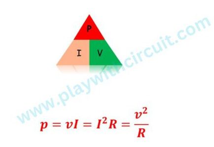
We can calculate the power dissipated by a resistance by using Ohm’s Law.
Types of Resistors
There are different types of resistors available and their properties may vary based on the type. For designing any circuit, these properties will help you select the right type of resistor. Different types of resistors are used in different applications.
Linear Resistors
The resistors whose values change with change in applied temperature and voltage are known as linear resistors. There are two types of linear resistors: Fixed resistors and Variable resistors.
Fixed Resistors
These resistors have a specific value and these values cannot be changed. Fixed resistors are available in different forms and materials, each with its own characteristics and specifications.
Here are some common types of fixed resistors:
Carbon Composition Resistors
Carbon composition resistors are one of the most widely used types. They are made by mixing carbon particles with a binder material and shaping them into a cylindrical form. Their resistance mainly depends on three main factors: the quantity of carbon included, cylindrical rods cross-sectional region and solid cylindrical rod’s length.

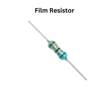
Film Resistors
Film resistors are constructed by depositing a resistive material on an insulating substrate. The resistive material can be metal or metal oxide. Film resistors offer higher accuracy and stability compared to carbon composition resistors. They are used in filter circuits, less noise analog signal circuits & bridge circuits.
Wirewound Resistors
Wirewound resistors are constructed by winding a resistive wire, typically made of an alloy like nichrome, around a core of non-conductive material like ceramic, plastic, and glass. They offer high precision, low noise, and high power ratings. Wirewound resistors are commonly used in precision measurement equipment and high-power applications.

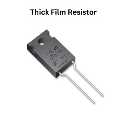
Thick Film Resistors
Thick film resistors are created by applying a resistive paste on a ceramic substrate and then firing it to form a solid film. They provide good accuracy, stability, and cost-effectiveness. Thick film resistors are widely used in consumer electronics, telecommunications, and automotive applications.
Variable resistors
These resistors do not have a specific value and the values can be changed with the help of dial, knob, and screw. These resistors are used in radio receivers for controlling volume and tone.

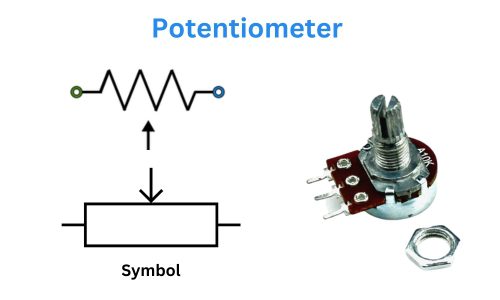
Potentiometer
A potentiometer is used as a potential divider. It generates a voltage signal depending on the location of the potentiometer. It can be used in a very wide variety of applications including an amplifier gain control, measurement of the distance or angles, tuning of the circuits, etc.
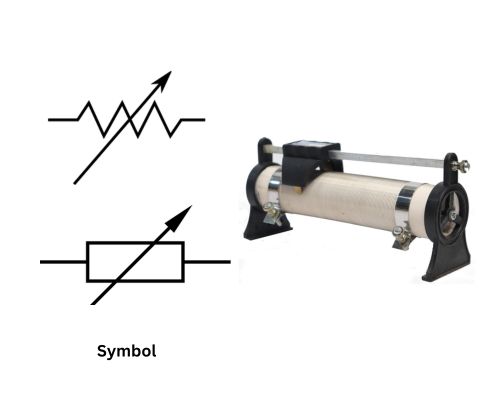
Rheostats
Rheostats are used as variable resistors. They can use only 2 terminals where one connection is connected at one end of the resistive element, the other is at the wiper of the variable resistor. Earlier they were used as the power controlling devices but now they are replaced by high-efficiency switching electronics.
Non-linear resistors
In non-linear resistors, values change according to the temperature and voltage applied and are not dependent on Ohm’s law. Following are the different types of non-linear resistors:
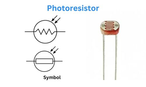
Light-dependent resistor / Photoresistor
These types of resistors change their resistance with the level of light. LDRs are made from semiconductor materials to enable them to have their light sensitive properties. They are commonly used in circuits where light sensing or detection is required including photographic light meters, lighting controls for street lamps, etc.
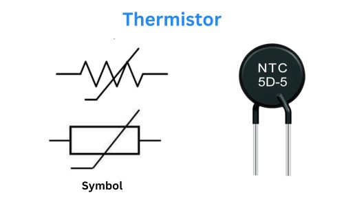
Thermistor
The thermistor is a heat-sensitive resistor whose resistance varies with temperature. Thermistors are made of semiconductor materials that exhibit a high temperature coefficient of resistance (TCR)
They are available in two types – NTC (Negative Temperature Coefficient) and PTC (Positive Temperature Coefficient). In NTC thermistors, resistance decreases as temperature increases. While in PTC thermistors, resistance increases as temperature increases.
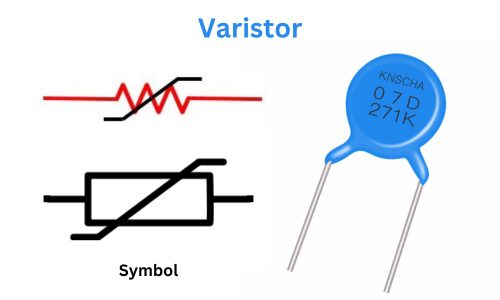
Varistor
Varistor is used to protect electronic circuits from voltage surges or transient overvoltage events. It is a type of voltage-dependent resistor that exhibits a non-linear resistance characteristic in response to changes in voltage. They are designed to have a high resistance at normal operating voltage levels. However, when a voltage surge occurs, its resistance decreases significantly, allowing it to absorb and dissipate the excess energy.
It diverts excessive voltage away from sensitive electronic components, preventing damage to the circuitry.
Uses of Resistors Based on the Type
| Types of resistors | Uses |
|---|---|
| Fixed resistor | Used in an electronic circuit where a specific and constant resistance value is required |
| Variable resistor | Used for volume controls in audio equipment, brightness controls in lighting systems, and signal level adjustments in amplifiers |
| Film Resistors | Used for circuits that require precise resistance values and high-frequency applications |
| Wire wound resistor | Used in high power rating devices and industrial equipments, testing and measuring devices |
| Light-dependent resistor or photoresistor | Used in light sensor applications |
| Varistor | Used for spike and surge protection |
| Potentiometer | Used as a voltage divider |
| Thermistor | Used in temperature sensing and control applications such as automotive systems, Consumer Electronics, etc. |
FAQ’S
What is the purpose of a resistor?
A resistor regulates or limits the current flowing in electrical or electronic circuits. It also divides voltage in a circuit by creating a voltage drop.
What is the formula of resistance?
R = V/I is the resistance formula.
What are the four power ratings of resistors?
The common standard power ratings of resistors are 0.25W, 0.5W, 1W, 2W, 5W, and 25W.
What is the formula for power rating?
The formula for power rating given by P = IV, where P is power in watts, I is current in amperes, V is potential difference in volts.
How do resistors work?
Resistors work by limiting or resisting the flow of electric current in a wire or other electrical component. As a result, the amount of current present in the circuit decreases.
What is a shunt resistor?
A shunt resistor is a type of resistor that creates a low resistance path to allow most of the electric current through the circuit. They are commonly used in current measuring devices known as ammeters.


