
Capacitors are essential electronic components used in almost every electronic circuit. They are one of the basic passive components along with resistors that we use in electronics. They are widely used in televisions, radios, and other kinds of electronic equipment.
In this article, we’ll learn exactly what a capacitor is, its working, importance and how it’s used in electronics. We’ll also look at the types of capacitors.
What is Capacitor?
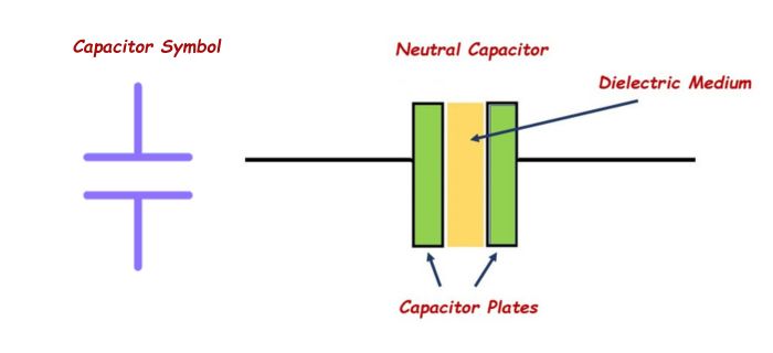
A capacitor is an electronic component that stores the energy in an electric field. It consists of two conductive plates separated by an insulating material, called the dielectric. This dielectric material could be waxed paper, mica, ceramic, or plastic. When a voltage is applied across the plates, an electric field is created, which stores energy in the dielectric.
 Capacitors play a critical role in filtering out unwanted noise and smoothing out voltage spikes, making them essential for the proper functioning of electronic circuits.
What is Capacitance?
Capacitance is the electrical property of a capacitor. The amount of energy that can be stored in a capacitor depends on its capacitance, which is measured in farads.
The capacitance of a capacitor depends on several factors, including the surface area of the plates, the distance between the plates, and the type of dielectric material used.
Capacitance can be calculated using the formula C=Q/V, where C is capacitance, Q is the charge stored on the plates, and V is the voltage across the plates.
Capacitors with higher capacitance values are able to store more electrical energy for a given voltage than capacitors with lower capacitance values. For example, a capacitor with a capacitance of 1 farad can store one coulomb of electrical charge for every volt applied to it.
Standard Units of Capacitance
The unit of a capacitor is farads (F). One farad is a large amount of capacitance so, most of the capacitors we come across are just fractions of a farad—typically microfarads (μF), nanofarads (nF) or Picofarad (pF).
- Microfarad (μF) 1μF = 1/1,000,000 = 0.000001 = 10-6 F
- Nanofarad (nF) 1nF = 1/1,000,000,000 = 0.000000001 = 10-9 F
- Picofarad (pF) 1pF = 1/1,000,000,000,000 = 0.000000000001 = 10-12 F
How Capacitor Works
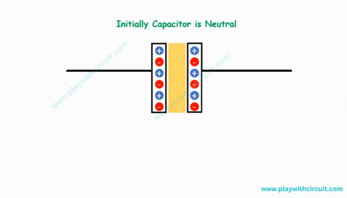
Let us consider the parallel plate capacitor. When no voltage source is applied on the capacitor, the amount of positive charge and negative charge is equal which means the metal plates are electrically neutral.
When we connect a DC voltage source across the capacitor, one plate is connected to the positive end of the battery and the other to the negative end. The current will try to flow or electrons start moving from the negative terminal of the battery through the conductive wire. But the dielectric material present between plates opposes the movement of electrons, so charge will start accumulating on the plate.
Positive plate accumulates positive charges from the battery, and the negative plate accumulates negative charges from the battery. So, an electric field appears across the capacitor.
After a point, the capacitor holds the maximum amount of charge as per its capacitance with respect to this voltage. When the capacitor is fully charged (voltage between the plates is equal to the source voltage), the capacitor stops charging. When the battery is removed from the capacitor, the two plates will retain its charge for a certain time. Thus, it acts as a source of electrical energy.
Capacitors are designed to operate at a specific maximum voltage. If the external voltage applied to the capacitor exceeds its maximum voltage, the electrons start moving between the plates. This can cause permanent damage to the capacitor.
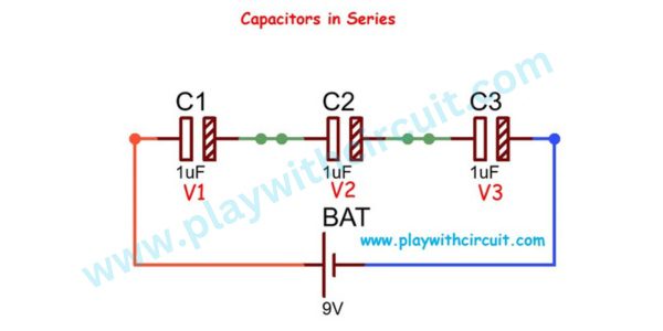
Capacitors in Series
In series combination, the same electrical current flows through each capacitor and the applied voltage V is divided across each capacitor. Due to external applied voltage each of the capacitors acquires an identical charge Q.
The sum of the capacitor voltages must equal the source voltage (Kirchhoff’s voltage law)
V = V1 + V2 + V3
As for any capacitor, the capacitance is (V=Q/C). The potentials across capacitors 1, 2, and 3 are, respectively,
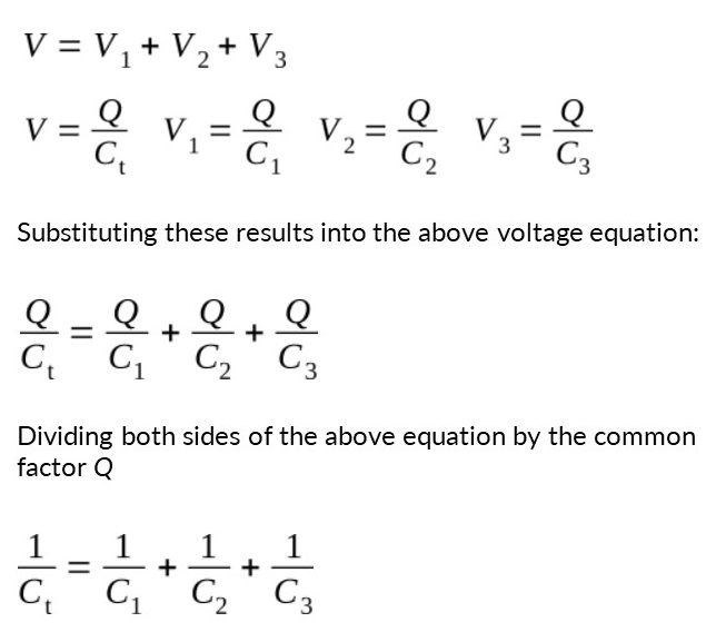
It is evident from the above formula that the total capacitance of capacitors connected in series is less than the capacitance of any of the individual capacitors.
The figure below shows a circuit containing three series capacitors each of 1 µF and a battery with voltage 9 V.
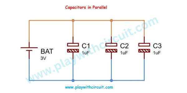
Capacitors in Parallel
In a parallel combination of three capacitors, one plate of each capacitor is connected to one terminal of the source, while the other plate of each capacitor is connected to the other terminal of the source. As the capacitors are connected in parallel, they all have the same voltage V across their plates but they may store a different charge.
The total charge Qt is the sum of the charges on each capacitor:
Q = Q1 + Q2 + Q3
From the equation C=Q/V, it follows that Q=CV
So the charges across each capacitor is Q1 = C1V, Q2 = C2V, and Q3 = C3V
By substituted these results into the above equation, we obtain
CtV = C1V + C2V + C3V
Dividing both sides of the above equation by the common factor V, we get
C = C1 + C2 + C3
This equation states that the total capacitance of a number of capacitors connected in parallel is the sum of each capacitance.
The figure below shows a circuit containing three series capacitors each of 1 µF and a battery with voltage 3 V.
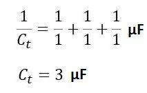
Total capacitance of circuit is:
C = 1 µF + 1 µF + 1 µF = 3 µF
How Does a Capacitor Work in an AC Circuit?
When we apply an ac supply across the capacitor, the capacitor alternately charges and discharges at a rate determined by the frequency of the supply. It charges and discharges continuously, due to continuous change in the voltage levels. Capacitance in AC circuits depends upon the frequency of the supplied voltage.
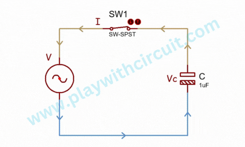
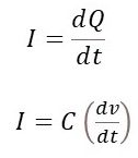
In ac circuits, current is directly proportional to the rate of change of supplied input voltage, which can be expressed as,
Capacitors also exhibit capacitive reactance, which is the opposition to the flow of AC current. The capacitive reactance is inversely proportional to the frequency of the AC signal and the capacitance of the capacitor. When the frequency increases, the capacitive reactance decreases, allowing more current to flow through the capacitor.
The phase relationship between the voltage and current in an AC capacitance circuit:
From the phasor diagram below, we can see that the current is leading the voltage by 900. So we can say that in a purely capacitive circuit the alternating voltage lags the current by 90 degree.
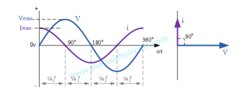
When we increase the voltage, the capacitor charges and attains its maximum value and, therefore, a positive half cycle is obtained. If we decrease the voltage, the capacitor discharges, and the negative half cycle is formed. This cycle of charging and discharging of the capacitor continues.
How Does a Capacitor Work in a DC Circuit?
When a DC voltage is applied, across an uncharged capacitor, it allows current to flow across it and charges up until the voltage across it becomes equal to the applied voltage. Once fully charged, the capacitor blocks the flow of direct current, acting as an open circuit. They act like a temporary storage device and hold this charge indefinitely as long as the supply voltage is present.
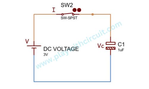
Thus a capacitors charging current can be defined as: i = CdV/dt.
It is important to note that capacitors in DC circuits do not have the continuous charging and discharging cycles as seen in AC circuits. Instead, they reach a steady state where no further charge is accumulated, and they effectively behaves like a break in the circuit.
How Capacitors are used in Electronics?
Capacitors are used in various ways in electronics circuits. Different circuits require different capacitors with particular properties like value range, value efficiency, electric current capacity, temperature stability, etc. There are various capacitor types available that have large value ranges, and others may have smaller values.
Following are the different applications of capacitor used in different electronics circuits:
-
Energy Storage: Capacitors are able to store electrical charge, which can be used to power various electronic devices. They can quickly discharge the stored energy when needed, making them ideal for use in high-power applications.
-
Signal Filtering: Capacitors can be used to filter out unwanted signals from electronic circuits. They can block DC signals and allow AC signals to pass through, which is useful for applications such as audio amplification and power supply regulation.
-
Timing Circuits: Capacitors can be used to create timing circuits, which control the rate at which a circuit changes state. This is useful for applications such as oscillators, timers, and pulse generators.
-
RF coupling and decoupling: Coupling capacitors are used in electronic circuits to block unwanted DC components and pass the desired AC signal. Decoupling capacitors are used in electronic circuits to prevent quick voltage changes by acting as electrical energy reservoirs. Thay maintain a stable voltage supply. They allow DC components to pass while blocking AC components.
-
Power Factor Correction: Capacitors can be used to improve the power factor of electronic devices. They can reduce the amount of reactive power in a circuit, which can improve energy efficiency.
Different Types of Capacitors
There are different types of capacitors, each with their own unique characteristics and uses. Capacitors are mainly classified into two types: Fixed capacitors and Variable capacitors
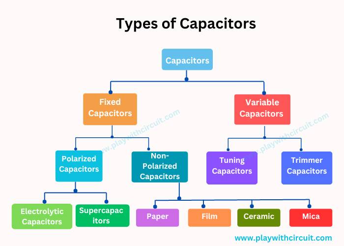
Fixed capacitor
Fixed capacitor is a type of capacitor which has a fixed amount of capacitance. You can’t adjust the capacitance of a fixed capacitor.
Fixed capacitors can be classified into Polarized Capacitors and Non-Polarized Capacitors.
Polarized Capacitors
Polarized Capacitors have specific positive and negative polarities. They can be connected only in one way in the circuit. The positive terminal should be connected to the positive end of supply and negative to negative end.

The electrolytic capacitors and the supercapacitors are the sub-types of the polarized capacitor. Let’s discuss each of these types in detail.
-
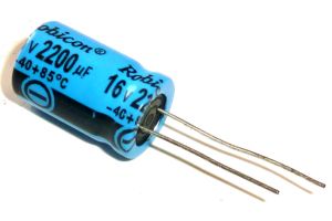
Electrolytic Capacitors
Electrolytic capacitors consist of two conductive plates separated by an electrolyte-soaked material. An electrolyte is a gel or fluid in which the concentration of ions is very high. Electrolytic capacitors have a very high capacitance value that makes them highly useful for sending low-frequency signals. They are polarized, which means the anode has more positive voltage than the cathode. They are extensively used for noise filtering, low-pass filters, audio amplifier circuits, decoupling in power supplies and more.
Tantalum capacitors are another type of Electrolytic capacitors whose anode is made up of tantalum on which a very thin insulating oxide layer is formed which acts as a dielectric and the electrolyte acts as a cathode which covers the surface of oxide layer. They have a lower ESR (Equivalent Series Resistance) and can handle higher frequencies. They are commonly used in applications where high stability and low noise are required.
-
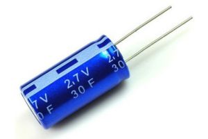
Supercapacitors
Supercapacitors, also known as ultracapacitors or double-layer capacitors, are a type of capacitor that can store an extremely large amount of charge. The maximum charge voltage of a supercapacitor lies between 2.5 and 2.7 volts. They are commonly used in applications that require a lot of energy in a short amount of time, such as in electric vehicles.
Non-Polarized Capacitors
A non-polarized capacitor is a type of capacitor that has no implicit polarity. It can be used either way in a circuit. They are mainly used in circuits of coupling, decoupling, feedback, compensation, and oscillation.
-
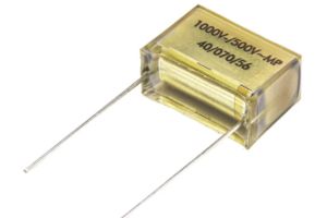
Paper Capacitors
Paper Capacitors is a type of capacitor in which paper is used as the dielectric to store electric charge. It consists of paper sheets and aluminium sheets. To protect the paper sheet from the outside environment, it is covered with wax or oil.
-
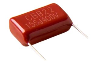
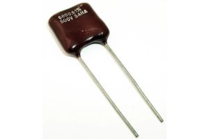
Film Capacitors
Film capacitors are made from a thin plastic film and are relatively cheap, stable and have low self-inductance and ESR. They are used in applications that require high voltage, high frequency, and high stability. There are many types of film capacitors, including polyester film, metallized film, polypropylene film, PTFE film and polystyrene film.
-
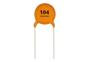
Ceramic Capacitors
Ceramic capacitors are the most commonly used capacitors and use the ceramic material as a dielectric. They are known for their high capacitance-to-size ratio, which means that they can store a relatively large amount of electrical charge in a small package. They are commonly used in printed circuit boards(PCB) that are used in high-density applications. The two common types of ceramic capacitors are multilayer ceramic capacitor (MLCC) and ceramic disc capacitor.
-
Mica Capacitors
Mica capacitors are made from thin sheets of mica and metal foil. There are two types of mica capacitors which are clamped capacitors & silver mica capacitors. Generally silver mica capacitors are preferred over clamped capacitors due to their superior characteristics.They have a very high stability and are commonly used in high-frequency and high-temperature applications.
Variable Capacitors
Variable capacitor is a capacitor in which capacitance can be adjusted by turning a knob or dial. can be adjusted to store different amounts of electrical charge. These capacitors provide the capacitance values so as to vary between 10 to 500pF.

They are very versatile capacitors and are used in a varied range of applications such as radio tuning circuits, motors, electrical power systems, etc. The main types of variable capacitors are Tuning capacitors and Trimmer capacitors.
Tuning Capacitors
Tuning capacitor contains a stator, a rotor, a frame to support the stator and a mica capacitor. Its metal plates are arranged in such a way that the rotor plates move between the stator plates. When the position of rotor plates is changed, the capacitance value is also changed.
These types of capacitors are generally used in the receivers of radio which have LC circuits. 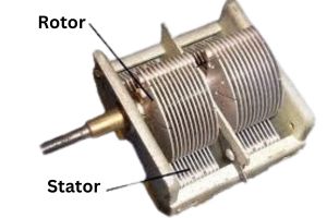
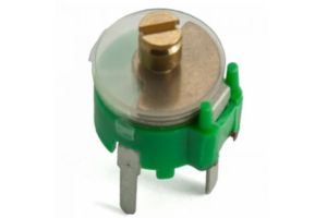
Trimmer Capacitors
Trimmer capacitors are used to adjust the capacitance accurately initially in the circuit and after adjustment it can be fixed to a certain capacitance value and is no longer required to change the capacitance during use. It is often used as a compensation or correction capacitor in various tuning and oscillation circuits. There are two types of trimmer capacitors: air trimmer capacitor and ceramic trimmer capacitor depending on the dielectric material used.
I hope by reading this article you have gained some basic knowledge on capacitors and why we need capacitors in circuits. Thanks for reading.
FAQ’S
What is capacitor and its uses?
A capacitor is an electronic component that stores electrical energy. It consists of two conductive plates separated by an insulating material known as a dielectric. When a voltage is applied across the capacitor, it accumulates electrical charge on its plates. Capacitors are used in timing circuits, oscillators, filters, coupling and decoupling, power factor correction, etc.
What are the two major groups of capacitors?
Capacitors are divided into two major groups: Fixed capacitors having fixed capacitance values and variable capacitors having variable or adjustable capacitance values.
What is the SI unit of a capacitor?
The SI unit of capacitance, which represents the measurement of a capacitor’s ability to store electrical charge, is the farad (F).