
Logic gates are the basic building blocks of digital circuits. They perform logical operations that are required by any digital circuit. These circuits process information in the form of binary signals, where each signal can exist in one of two states: HIGH (1) or LOW (0). In these circuits, logic gates are used to process the binary signals and make logical decisions.
The versatility of logic gates makes them indispensable components in designing and operating a wide range of electronic systems and devices, including microprocessors, microcontrollers, memory systems, communication devices, embedded systems, etc.
To understand the logic gates and their role in digital electronics we will start by learning the basics of binary numbers and digital signals. Then we will explore logic gates, their types, and how they work in digital electronics.
Binary Numbers
The binary system has a base of 2, i.e., it uses two digits: 0 and 1. In contrast to the decimal system, which is represented with a base of 10, i.e., it uses 10 digits (0-9). Each digit in a binary number is called a bit. Decimal numbers can be easily represented in the binary number system.
For instance, taking the decimal number 3, its representation in the decimal system is (3)10, where the subscript 10 indicates the base. In binary, the same number is represented as (11)2, denoting a base-2 system. Therefore, “10” in binary represents the decimal number 2.
Decimal to Binary Conversion Table
| Sr. No. | Decimal Number | Binary Number |
|---|---|---|
| 1 | 0 | 0000 |
| 2 | 1 | 0001 |
| 3 | 2 | 0010 |
| 4 | 3 | 0011 |
| 5 | 4 | 0100 |
| 6 | 5 | 0101 |
| 7 | 6 | 0110 |
| 8 | 7 | 0111 |
| 9 | 8 | 1000 |
| 10 | 9 | 1001 |
| 11 | 10 | 1010 |
| 12 | 11 | 1011 |
| 13 | 12 | 1100 |
| 14 | 13 | 1101 |
| 15 | 14 | 1110 |
| 16 | 15 | 1111 |
Analog and Digital Signals
An analog signal is a continuous time-varying voltage or current signal, which is continuous and can take any value within a range. In contrast, digital signals are a type of electronic signal that represents information using discrete values, typically in the form of binary digits 0 and 1.
In digital systems, information is encoded into binary digits, commonly referred to as bits. Each bit can exist in one of two states, 0 or 1, corresponding to the OFF/ON or LOW/HIGH states in the electronic circuits.
What are Logic Gates?
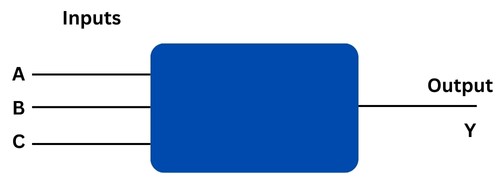
Logic gates are electronic circuits that perform logical operations on one or more binary inputs to produce a single binary output. In a digital circuit, logic gates make decisions based on a combination of digital signals coming from its inputs.
The behaviour of the logic gate can be understood using a Truth Table that outlines the possible combinations of inputs and their corresponding outputs.
Logic gates are typically made up of electronic components such as transistors, diodes, and resistors. These components are interconnected in a specific way to create the desired logical operation. Transistors, especially MOSFETs, are commonly used in the construction of logic gates.
Types of Logic Gates
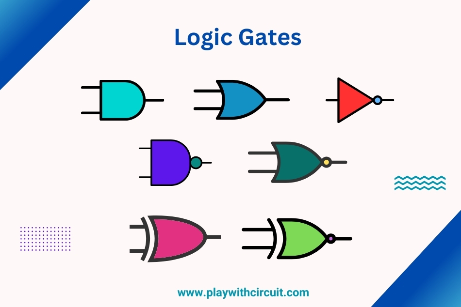
There are 3 types of logic gates used in performing operations in digital systems. Let’s understand all three types of logic gates in depth:
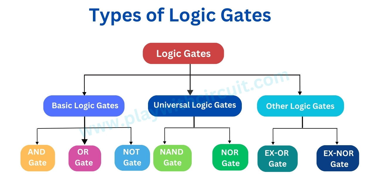
Basic Logic Gates
All digital systems can be constructed by only three basic logic gates. Basic gates include NOT, AND, and OR.
AND Gate
An AND gate is a fundamental digital logic gate that performs the logical AND operation. The AND gate takes two or more binary inputs and produces a single output based on the logical multiplication of these inputs.
The following figure shows the Truth Table and symbol of an AND gate having two inputs A, B and one output, Y.
Here the AND gate produces an output , which is the logical AND or boolean multiplication of two inputs A, B.
Boolean multiplication follows the same basic rules of binary multiplication:
0 . 0 = 0
0 . 1 = 0
1 . 0 = 0
1 . 1 = 1
The Boolean expression of a 2-input AND gate can be expressed as follows:
Y = A.B
So, the output is 1 only when both inputs are 1; otherwise, it is 0. When AND gate produces high output (1) the LED turns ON(becomes Green).
Similarly, when there are ‘n’ inputs, then the AND gate gives an output, which is the logical AND of all those inputs.
OR Gate
OR Gate is a digital logic gate that performs a logical OR operation. It has two or more inputs and one output.
The Truth Table and working of 2-input OR gate is given below:
Here, OR gate produces an output , which is the logical OR or Boolean addition of two inputs A, B. The logical OR operation is represented mathematically by a ‘+’ between the two variables.
The basic rules for Boolean addition are as follows:
0 + 0 = 0
0 + 1 = 1
1 + 0 = 1
1 + 1 = 1
The Boolean expression of a 2-input OR gate can be expressed as follows:
Y = A + B
From Truth Table it is evident that OR Gate produces a high output (1) if at least one of the two inputs is high. In other words, the output is low (0) only when all the inputs are low. As shown above, when output is high (1), the LED turns ON(becomes Green).
Similarly, if there are ‘n’ inputs, then the OR gate produces an output, which is the logical OR of all those inputs.
NOT Gate
NOT Gate is also known as an inverter. It produces the inverse or complement of its input signal. It takes an input signal and produces the opposite output. In other words, if the input is high (1), the output is low (0), and if the input is low (0), the output is high (1).
The following figure shows the Truth Table and working of NOT gate:
Here, A is the input and Y is the output of NOT gate. It produces an output , which is the complement of input, A.
Thus the Boolean expression for NOT gate is

Thus if A = 0, Y = 1 and if A = 1 then Y = 0. As shown above, when output is high LED glows (becomes Green).
Universal Logic Gates
Universal logic gates are specific types of logic gates that can be used to implement any other type of logic gate. They are considered “universal” because you can create circuits that perform the functions of basic gates using only these universal gates. Two commonly known universal logic gates are the NAND gate and the NOR gate.
NAND Gate
The NAND Gate is a combination of an AND gate followed by a NOT gate and implies an AND function with a complemented (inverted) output. Its output is low (0) only when both inputs are high (1), and it produces a high (1) output for all other input combinations.
The following figure shows the Truth Table and working of 2-input NAND gate:
Here A, B are the inputs and Y is the output of NAND gate.
The Boolean expression for the output of a 2-input NAND gate is
![]()
From Truth Table it is clear that for a 2-input NAND gate, output Y is LOW only when inputs A and B are HIGH; Y is HIGH when either A or B is LOW, or when both A and B are LOW. When output is high, LED glows.
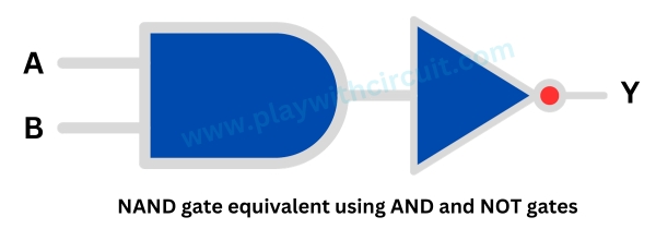
NAND Gate Equivalent using AND and NOT Gates
A NAND gate is equivalent to an inverted-input AND gate that means a complement operation is performed on the output of the AND gate.
Using NAND Gates to create other Basic Logic Gates
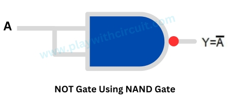
NAND gates can be used to create other basic logic gates. That’s why it is called Universal Gate. Let’s see how NAND gate can be used to make other gates.
The following figure shows a NAND gate connected to create a NOT circuit.
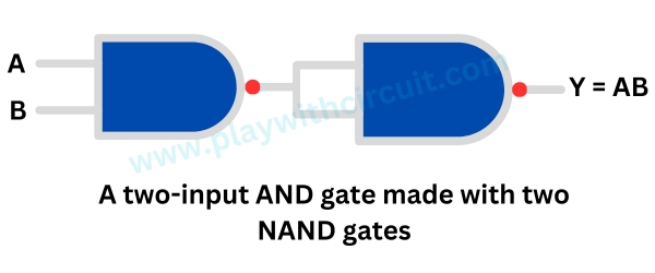
The following figure shows two NAND gates connected to create a two-input AND gate.
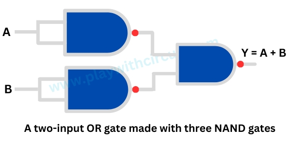
The following figure shows three NAND gates connected to create a two-input OR gate.
NOR Gate
NOR gate is a combination of an OR gate followed by a NOT gate or an inversion of the OR gate. Its output is high (1) only when both of its inputs are low (0), and it produces a low (0) output for all other input combinations.
The Truth Table and working of 2-input NOR gate are given below:
Here A, B are the inputs and Y is the output of two input NOR gate.
The Boolean expression for the output of a 2-input NOR gate can be written as
![]()
From above figure, when both inputs are Low and output is High then LED turns Green.
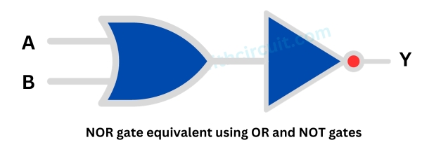
NOR Gate Equivalent using OR and NOT Gates
Using NOR Gates to create other Basic Logic Gates
Here we will discuss how the AND, OR and NOT logic gates can be accomplished using the NOR gate only.
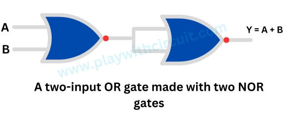
The following figure shows two NOR gates connected to create a two-input OR gate.
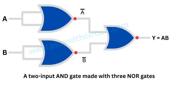
The following figure shows three NOR gates connected to create a two-input AND gate.
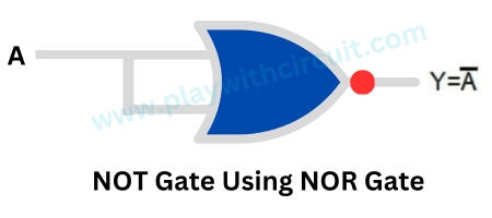
The following figure shows a two-input NOR gate connected to produce a NOT gate.
Derived Logic Gates
Derived logic gates are often used in digital circuit design for specific applications like half adders, full adders, and subtractors. Two derived logic gates made from OR and NOR gates are XOR Gate and XNOR Gate.
XOR Gate
An XOR gate, or exclusive OR gate, is a digital logic gate that performs the exclusive disjunction operation. Its output is a logical “1” if the two input values differ, i.e., its output is a logical “1” if either of its inputs are 1, but not at the same time (exclusively). The XOR gate is often represented by the symbol ⊕.
The following figure shows the Truth Table and working of 2-input XOR gate:
Here A, B are the inputs and Y is the output of two-input XOR gate. When output is High, LED turns Green.
Thus output, Y = A ⊕ B
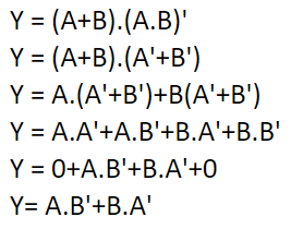
Now let us simplify this Boolean expression,

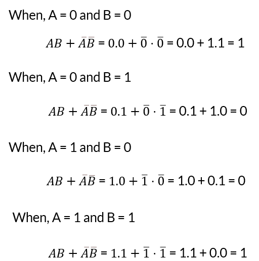
Let us prove the above expression using Truth Table,
When, A = 0 and B = 0
When, A = 0 and B = 1
When, A = 1 and B = 0
When, A = 1 and B = 1
Hence, it is proved that the Boolean expression for A ⊕ B is equal to AB ̅ + ĀB.
XOR Gate Equivalent Circuit
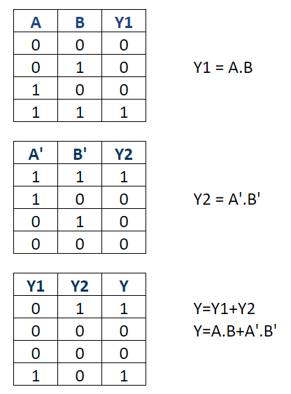
The XOR gate with 2-inputs is designed using NAND, OR and AND gates as shown below:
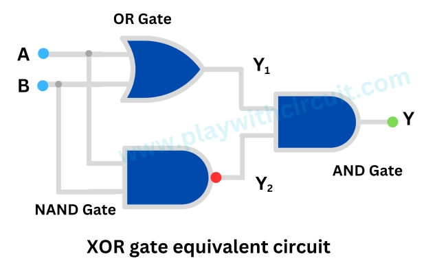
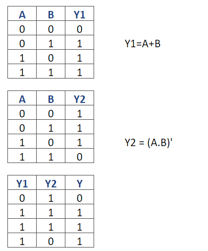
Now let us understand the working of the above circuit using following tables:
XNOR Gate
An XNOR gate, also known as an equivalence gate, is a digital logic gate that outputs true (or 1) only when the number of true inputs is even. It returns false (or 0) if the number of true inputs is odd.
The following figure shows the truth table and working of 2-input XNOR gate.
Here A, B are the inputs and Y is the output of two-input XNOR gate. From the above figure, when output is High, LED turns Green.
XNOR operation is equivalent to the inverse of the XOR gate output. The symbol for XNOR is often represented by a ⊙. The expression of XNOR operation between variables A and B is represented as A ⊙ B.
Now let us satisfy the Truth Table by the equation
![]()
Hence, it is proved that
![]()
XNOR Gate Equivalent Circuit
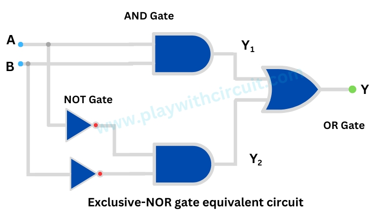
Now let us understand the working of the above circuit using following tables:
Applications of Logic Gates
1. Arithmetic Circuits: Logic gates are extensively used in arithmetic circuits such as adders and subtractors.
2. Memory Units: Flip-flops and latches, constructed using logic gates, form the basis of memory units in computers and other digital devices.
3. Multiplexers and Demultiplexers: Logic gates are integral components in multiplexers and demultiplexers, facilitating the efficient transmission of data over communication channels.
4. Digital Display Systems: Seven-segment displays, commonly used in digital clocks and calculators, rely on logic gates for accurate and synchronized digit representation.
5. Programmable Logic Controllers (PLCs): Industrial automation heavily depends on PLCs, where logic gates are used to control and monitor various processes.
7. Microprocessors and Microcontrollers: Microprocessors and microcontrollers utilize complex arrangements of logic gates to execute instructions and perform computations.


