
Inductors are fascinating electronic components that play an important role in a wide range of electronic circuits. They are coil-like structures that you can find in most electronic circuits.
This article aims to provide a comprehensive understanding of the inductor, how it works, its various uses, and different types of inductors available in the market.
What is an Inductor?
Inductors, often referred to as coils or chokes, are passive electronic components that store energy in the form of a magnetic field when electric current flows through it. They consist of an insulated wire that is wound around a core made of various materials such as iron, ferrite, or air. Inductors are typically available in the range from 1 µH to 20 H.
The symbol of an inductor is shown in the below image:

Inductance
Inductance is a property of an inductor that opposes any change in magnitude or direction of current passing through it. It is the ratio of voltage (EMF) and current change inside the coil. A higher inductance value indicates that the inductor can store more energy in the form of the magnetic field.
Inductance depends on several factors, including the number of turns in the coil, the cross-sectional area of the core, the permeability of the core material, and the coil’s physical dimensions. The alphabet ‘L’ is used for representing the inductor, and it is measured in Henry.
For a simple single layer inductor, the inductance is described by the following formula:
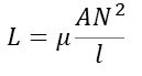
Where,
L is the inductance in henries,
μ is the permeability of the core material,
A is the cross sectional area of the coil,
N is the number of coils or turns,
l is the length of the coil.
How Inductor Works?
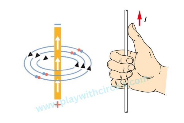
Before understanding the working of inductors, let us first understand how a conductor behaves when electric current flows through it. Let us consider a straight conductor.
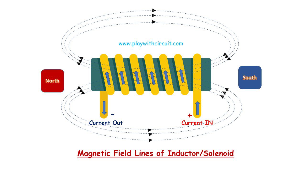
When a current flows through the conductor, a magnetic field is generated around it . This magnetic field is measured in the SI unit, Tesla (T). The direction of the magnetic field can be obtained using Maxwell Right hand Thumb Rule.
According to the rule, when holding a straight conductor carrying an electric current in your right hand with your thumb pointing in the direction of the current, the encircling direction of your fingers along the wire indicates the direction of the magnetic field lines surrounding the conductor.
Electromagnetic Induction
Electromagnetic induction is the process of generating an electric current in a conductor by moving it through a static magnetic field. The key factors that influence the magnitude of the induced current are the rate of change of the magnetic field and the characteristics of the conductor.
Faraday’s Laws of Electromagnetic Induction
It consists of two laws. The first law describes the induction of emf and the second law quantifies the emf induced in the conductor.
Faraday First Law of Electromagnetic Induction
Faraday’s First law states that whenever a conductor is placed in a varying magnetic field, an electromotive force (EMF) is induced.
Faraday’s Second law of Electromagnetic Induction
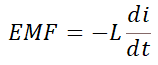
Faraday’s Second law states that the magnitude of the induced EMF in a circuit is equal to the rate of change of the magnetic flux linkage with respect to time.
Mathematically, Faraday’s second law can be expressed as:
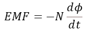
Where EMF is the induced electromotive force, N is the number of turns in the coil, and d(Φ)/dt is the rate of change of the magnetic flux linkage through the coil.
Lenz’s Law
Lenz’s law describes the direction of an induced current in a conductor when it is exposed to a changing magnetic field.
It states that the direction of the current induced in a conductor by a changing magnetic field is such that the magnetic field created by the induced current opposes the initial magnetic field which produced it. In the formula of Faraday Second Law of Electromagnetic Induction, the negative sign is introduced by Lenz law.
Self Inductance
Self-inductance is the phenomenon where a changing current in a coil induces an electromotive force in the same coil, opposing the change in current.
This property of the coil exists only for the changing current, which is the alternating current(ac) and not for the direct current(dc).
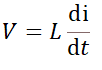
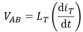
The induced voltage in an inductor may also be expressed in terms of the inductance (in henries) and the rate of change of current.
Here L is the Inductance in Henries.
When the alternating current is applied across the inductor
When the AC current changes direction, the inductor opposes this change by inducing a voltage that tries to counteract the change in current. This opposition to changes in current is due to the phenomenon of self-induction(Faraday’s law of electromagnetic induction). The induced voltage in the inductor is proportional to the rate of change of current.
As the frequency of the AC signal increases, the rate of change of current becomes higher, resulting in a stronger opposition from the inductor. This causes the inductor to have a higher impedance for higher frequency AC currents. Thus, the inductor opposes or blocks the passage of alternating current through it.
When the direct current is applied across the inductor
In the case of DC (direct current), which is a constant and unchanging current, the inductor allows the current to flow through it without significant impedance. This is because the rate of change of current is zero in a DC circuit, so the inductor does not oppose a steady current flow.
Inductor Circuits: Series and Parallel Connection
Inductors in Series
When the inductors are connected together in a straight line end to end then the inductors are said to be in a series connection.
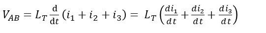
When inductors are connected in series, their total inductance adds up. The total inductance LT of the circuit is equal to the sum of all the individual inductances. The inductors in series have the same current flowing through them. However, the voltage across each inductor may differ based on their individual inductance values and the rate of change of current.
Consider the connection below:
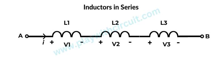
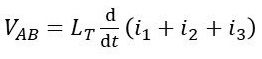
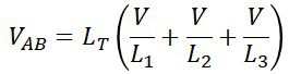
Here three inductors L1, L2 and L3 are connected together in series between points A and B. The total inductance of the circuit is:
The sum of the individual voltage drops across each inductor can be found using Kirchoff’s Voltage Law:
![]()
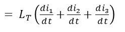
We know that the self-induced emf across an inductor is given by the equation
So, the total inductance can be written as
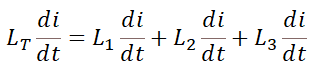
It is important to note that the total inductance of any two or more inductors connected together in series will always be greater than the value of the largest inductor.
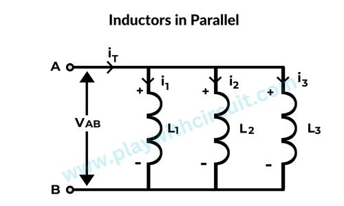
Inductors in Parallel
Inductors are said to be connected together in Parallel if two terminals of an inductor are connected to two terminals of another inductor.
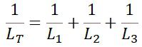
The total inductance of inductors connected in parallel can be calculated using the reciprocal of the sum of the reciprocals of the individual inductance values.
The total inductance (L) of inductors connected in parallel, can be calculated using the following formula:
The voltage drop across all of the inductors connected in parallel will be the same. Thus they have a Common Voltage across them:
![]()
Here, the current flowing through each inductor will be different. By using Kirchoff’s Current law, the total current is the sum of the current through each branch.
![]()
We know that the voltage across an inductor is:
Since voltages are equal, we can simplify the equation as,
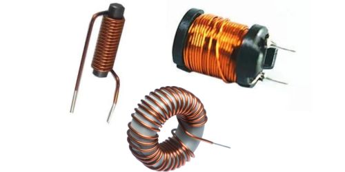
Types of Inductors
There are several types of inductors based on the core material used. The core material plays a crucial role in determining the inductor’s performance characteristics. Here are some common types:
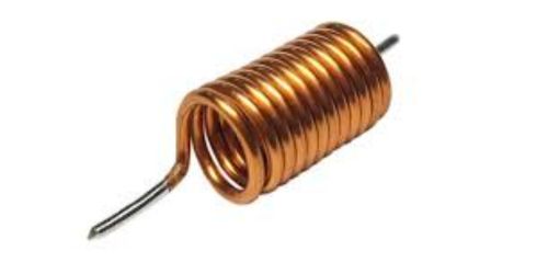
Air Core Inductor
As the name suggests, these inductors have no core material and are made of wire coils wound around a non-magnetic form. Air core inductors have low inductance values but offer low resistance and high frequency capabilities. They are commonly used in high-frequency applications like radio frequency (RF) circuits and radio receivers.
Ferrite Core Inductor
Ferrite core inductors use ferrite, a ceramic compound made from iron oxide(ferric oxide, Fe2O3) and other metal oxides, as the core material. Ferrite cores have high magnetic permeability, low electrical conductivity and low eddy current losses. These properties make ferrite core inductors suitable for high-frequency applications where low losses and high efficiency are required. They are commonly used in switch-mode power supplies, and electromagnetic interference (EMI) filters.
Powder Core Inductor
Powder core inductors use a powdered iron or ferrite core material. The powdered core is compressed and mixed with a binder to form a solid structure. This type of construction provides an advantage to the core, it stores a high level of energy compared to the other types. But iron cores are highly susceptible to core losses at high frequency. Thus, they are used for frequencies below 100 KHz.
Thus these inductors possess high-temperature coefficient stability. These are mainly used in switching power supplies.
Laminated Steel Core Inductor
In Laminated Steel Core Inductor a core is made of laminated steel sheets. These sheets are typically thin and insulated from each other to increase their electrical resistance and minimize eddy current losses.
The laminated steel core provides several advantages like high magnetic permeability of core and reduced magnetic flux leakage.
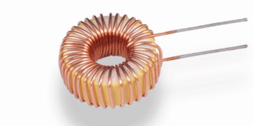
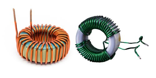
Toroidal Inductor
Toroidal inductors feature a core shaped like a doughnut (torus) and are often made of iron powder, ferrite, or laminated magnetic materials. The toroidal shape provides a closed magnetic path, thus improving the size and inductance. As toroidal inductors have fewer windings but high magnetic field and high inductance value, so the impedance is very less which in turn improves their efficiency.
Toroidal inductors are known for their compact size, low electromagnetic interference, and high efficiency. They are used in power supplies, audio systems, and electronic equipment where size and noise reduction are important factors.
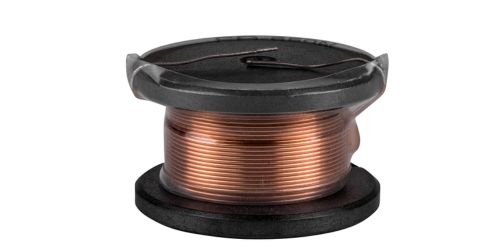
Bobbin Core Inductor
Bobbin Core Inductor or drum core inductor has a bobbin or spool shaped core structure. It is a cylinder with two flat discs at each end. The wire coil is wound around the bobbin to create the inductor’s primary winding. The core material can be made of ferrite, powdered iron, or other magnetic materials.
The core does not provide a closed magnetic path and has high saturation current at the expense of low inductance & EMI. It also provides a large air gap for its magnetic field to store more energy.
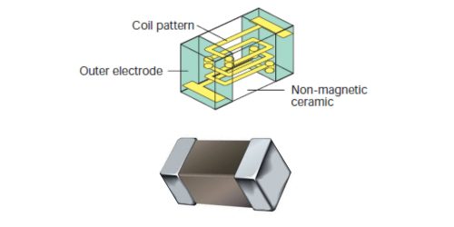
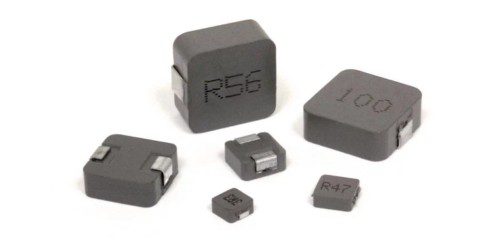
Multi-Layer Inductor
Multi-Layer inductors, also known as a chip inductor, is a type of inductor that has multiple layers of wire wound on top of each other. These inductors have large inductance due to an increase in the number of turns of the winding.
These inductors are commonly used in surface-mount technology (SMT) applications. The biggest advantage of these inductors is that we can get higher inductance results at lower operating frequencies. They can be used in signal processing modules like wireless LANs, Bluetooth, etc.
Thin Film Inductor
Thin Film Inductor is fabricated using thin film deposition techniques. It is constructed by depositing layers of conductive and insulating materials onto a substrate, creating a spiral or meandering pattern that forms the inductor’s coil. Thin film allows for improved electrical stability and resistance to vibration. They are used in wireless and LAN networks, power supplies, amplifiers, voltage controlled oscillators, impedance matching, extreme repeatability, etc.
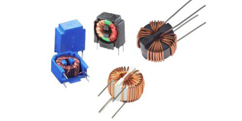
Coupled Inductor
Coupled inductor consists of two coils of wire wound around a common magnetic core. The changing magnetic field in the first winding induces an electromotive force (EMF) in the secondary winding. This phenomenon is called mutual inductance. They are commonly used in power supplies to step-up or step-down voltages, to isolate circuits from each other, and to filter electrical signals.
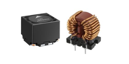
Power Inductor
These inductors are specifically designed to handle higher levels of current without reaching the magnetic saturation region and store larger amounts of energy compared to standard inductors. They are constructed with a core made of a magnetic material, such as ferrite or powdered iron, which enhances their magnetic properties. The core helps increase the inductance and allows the inductor to handle higher power levels.
Power Inductors are available from a few amps to a few hundred amps in both SMD and through-hole packaging. They are commonly used in various applications, including DC-DC converters, voltage regulators, power supply circuits, filters, etc.
Chokes
Chokes, also known as inductive chokes or simply coils, are designed for blocking (choking) high-frequency signals. It offers high impedance to high-frequency signals, effectively blocking or attenuating them. This makes chokes useful in applications such as power supply circuits, audio equipment, and radio frequency (RF) systems.
Variable Inductor
These inductors are designed to have variable inductance. One common method to achieve variable inductance is to have a movable core within the coil, which can be adjusted by rotating or sliding it. Moving the core along the winding will increase or decrease the permeability which affects the inductance.
Variable inductors have high-quality factors, low parasitic capacitance & outstanding high frequency (HF) characteristics. They can be used in circuits where the inductance needs to be adjusted to control the behaviour of the circuit. It is important to note that the range and precision of inductance adjustment may vary depending on the specific design and construction of the variable inductor.

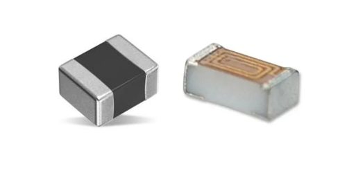
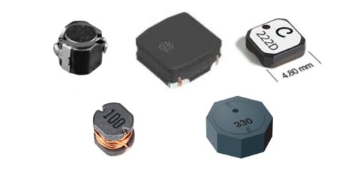
Shielded Surface Mount Inductor
A shielded surface mount inductor combines the benefits of both a surface mount inductor and electromagnetic shielding. This shield helps to contain and reduce the electromagnetic fields generated by the inductor, preventing them from interfering with nearby sensitive components or circuits.
These inductors are specially designed for PCB mounted applications. They are utilized in various circuits, including power supplies, filters, RF circuits, and audio amplifiers.

Molded Inductor
Molded inductors are coated with insulation such as molded plastic or ceramics. The core is made from ferrite or phenolic material. The molded package also helps in reducing electromagnetic interference (EMI) and ensures proper electrical insulation.
They are commonly used in various electronic applications, including power supplies, DC-DC converters, filters, and communication systems. They are particularly beneficial in harsh environments where protection against moisture, dust, and mechanical stress is crucial.
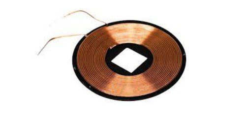
Wireless Charging Coils
These coils are used for inductive charging and wireless charging. They are installed into a device to receive a wireless signal that will be used to charge and power another device. They are typically made of a conductive wire, such as copper, wound into a specific shape. The coils are often circular or rectangular, with multiple turns to increase the inductance and improve the efficiency of power transfer.
These coils play a crucial role in the process of inductive power transfer, enabling convenient and cable-free charging of devices such as smartphones, smartwatches, and other portable electronics.
What are the uses of inductor?
Inductors have a wide range of applications in various electronic circuits and systems. Some of the key applications of inductors are:
Energy Storage: Inductors are commonly used to store energy in the form of a magnetic field. They can store electrical energy and release it back into the circuit when needed. Inductors are particularly useful in applications where a temporary power supply or energy buffer is required, such as in power supplies, converters, and energy storage systems.
Filtering: Inductors are extensively used in filtering circuits to suppress or attenuate specific frequencies. They are used in combination with capacitors to create low-pass, high-pass, band-pass, or band-stop filters. Inductors help block or pass certain frequencies, thereby reducing noise, eliminating unwanted signals, and ensuring a clean and stable output.
Power Electronics: Inductors play a crucial role in power electronics applications. They are used in switching regulators, voltage converters, and motor control circuits to regulate and control current and voltage levels. Inductors help smooth out current fluctuations, reduce ripple in power supplies, and maintain stable and efficient power delivery.
Transformers: Inductors are the fundamental components of transformers. Transformers utilize mutual inductance between primary and secondary windings to step up or step down voltage levels. They are widely used in power transmission and distribution systems, electrical appliances, audio amplifiers, etc.
In modern power supply designs, transformer windings are often integrated directly into the PCB to reduce size and improve efficiency. These PCB-integrated transformers are commonly used in switched-mode power supplies (SMPS) and other power conversion circuits.
Timing and Oscillation: Inductors are utilized in timing and oscillation circuits, such as oscillators and resonant circuits. They help in frequency determination and stability in applications like clock circuits, timers, and oscillators.
Sensors: Inductors can be used as sensing elements in various applications. They can be used in proximity sensors, inductive sensors, and inductive position sensors to detect the presence, position, or movement of objects based on changes in inductance. Inductive sensors are used in traffic lights that detect the amount of traffic and adjust the signal accordingly.
Induction motors: Inductors play an important role in the operation of induction motors. They are designed to have specific characteristics to optimize motor performance. In an induction motor, inductors are present in the stator, which is the stationary part of the motor. The inductors in the stator windings of an induction motor are responsible for producing the magnetic field that drives the motor’s operation. The inductance of the stator windings determines the strength and characteristics of the magnetic field generated.