
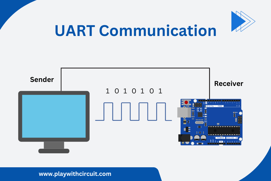
UART (Universal Asynchronous Receiver/Transmitter) is one of the simplest ways for two devices to exchange data with each other. Unlike other protocols such as SPI or I2C, UART only needs two wires: TX (to send data) and RX (to receive data). Because of its simplicity and reliability, UART is built into almost every microcontroller. In this article, we’ll explore about UART, how it works and UART flow control.
What is UART Communication Protocol?
UART is a hardware communication protocol used for serial communication between devices. Here, Asynchronous refers that there is no clock signal involved in communication. It is commonly used in microcontrollers, embedded systems, and various other devices for transmitting and receiving data.
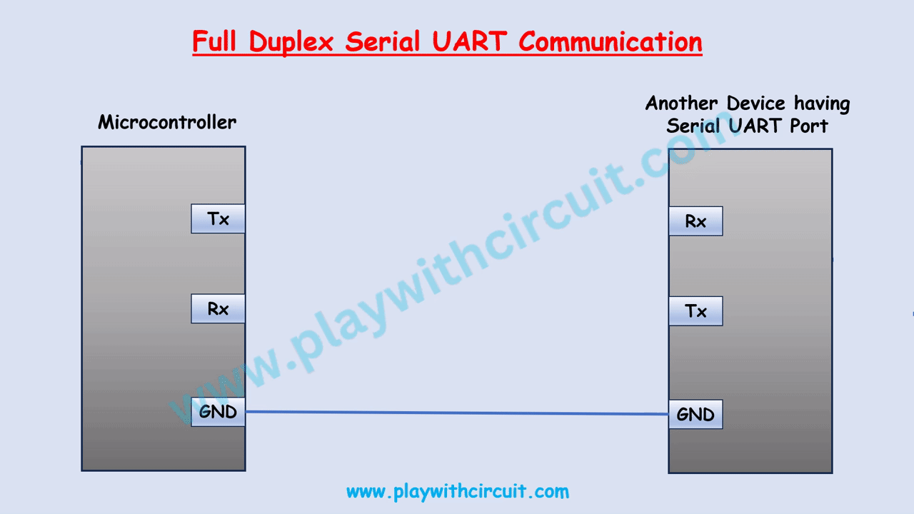
Typically, UART uses three pins for communication, one for transmitting (TX) and one for receiving (RX) and the third one is Ground pin. When one device wants to send data to another, it sends a series of bits (0s and 1s) serially through the TX pin.
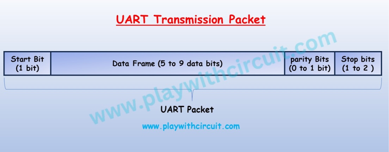
Before sending the data byte, it is first converted into a UART Packet and then sent through the Tx pin. Similarly, when the UART packet is received on the Rx pin its data is checked for integrity and actual payload is extracted from UART Packet.
UART Summary
Let’s take a look at the key characteristics of UART communication.
| Wires | Minimum 3 required |
| Speed | 9600, 19200, 38400, 57600, 115200, 230400, 460800, 921600, 1000000, 1500000 |
| Methods of Transmission | Asynchronous |
| Maximum Number of Masters | 1 |
| Maximum Number of Slaves | 1 |
💡Must Read
I2C Communication Protocol
This article explains what is I2C communication protocol and how it works.
SPI Communication Protocol
This article discusses the fundamentals of SPI, how it works and its configurations.
How UART Communication Works?
UART communication works by breaking data into packets and sending them bit by bit through the TX line. The receiver then reads these packets on its RX line. To understand how UART works, let’s first look at how the data is structured into a packet.
Understanding the UART Packet Structure
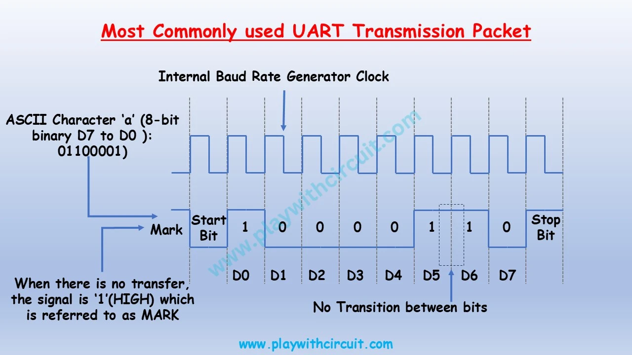
The UART module transmits and receives data using the standard NRZ (Non-Return-to-Zero) format. The NRZ format uses two logic states, VOH (Voltage Output High) and VOL (Voltage Output Low). The VOH (Mark) state represents a ‘1’ data bit and VOL (Space) state represents a ‘0’ data bit. The NRZ format states that consecutively transmitted data bits of the same value stay at the output level of that bit without returning to the neutral level between bits. An NRZ transmission port idles in the Mark (‘1’) state.
In UART each character transmission consists of a Start bit, followed by data bits, one optional parity or address bit, and ends with one or more Stop bits. The Start bit is always a Space (‘0’), while Stop bits are always Marks (‘1’). The most common data format consists of eight data bits and no parity bit and 1 stop bit is shown in the diagram.
The transmission begins with a start bit followed by D0(LSB) up to D7(MSB) and finally 1 stop bit indicating the end of UART Packet.
Configuring the UART Communication Parameters
In UART communication, both the transmitter and receiver must be configured with the same set of parameters; otherwise, data will be misread or lost. These parameters define the exact format and timing of the data exchange and are essential for reliable communication. The key parameters are:
Baud Rate
The baud rate is a measure of how many bits per second a communication channel can transmit. It determines the speed at which data is sent or received in serial communication.
Common baud rate values include 2400, 4800, 9600, 115200 and more. The choice of baud rate depends on the requirements of your specific project and the capabilities of the external device. Both the transmitting and receiving devices need to operate at the same baud rate to ensure data is properly sent and received.
If you set a UART communication channel to a baud rate of 115200, it means that the channel can transmit data at a rate of 115200 bits per second.
Data Bits
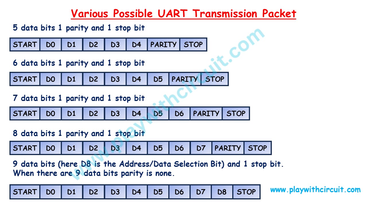
Data bits represent the number of bits in each data byte. Common values are 5, 6, 7, 8 or 9. The most common configuration is 8 data bits, which allows for 256 different values (2^8) in each byte.
Parity Bit
Parity is an error-checking mechanism. It can be set to “none,” “even,” or “odd.” When used, the UART system calculates and adds a parity bit to each byte, ensuring that the total number of ‘1’ bits (including the parity bit) is even or odd. The receiving device checks this parity bit to detect errors in the data. Parity can help detect single-bit errors but cannot correct them.
In Parity modes, the first eight bits of each byte are the data bits, and the ninth bit is the parity bit. Parity bits are used in error detection. Even Parity means that the expected number of ‘1’ bits in a character is an even number, while Odd Parity means that the expected number of ‘1’ bits in a character is an odd number. When in Even Parity mode, the parity bit will be set if the number of ‘1’ bits in the 8-bit transmit data is an odd number; when the number of ‘1’ bits are even, the parity bit is cleared. In Odd Parity mode, when the number of ‘1’ bits in the 8-bit transmit data is odd, the parity bit is cleared; when the number of bits are even, the parity bit is set. Following tables gives examples of how the parity bit value is determined.
Even/Odd Parity Examples
| Byte Value | Even Parity Bit Value | Odd Parity Bit Valu |
|---|---|---|
| 1010 1011 | 1 | 0 |
| 1010 100 | 0 | 1 |
Stop Bits
Stop bits indicate the end of a data byte. Common values are 1, 1.5 and 2 stop bits. The most common configuration is 1 stop bit, but older systems use 2 stop bits for added reliability. 1.5 stop bits is rarely used.
❕Note
In older systems with slow mechanical devices, two stop bits were used. It provided the receiving hardware sufficient time to process the incoming byte and prepare for the next one.
Start Bit
The UART data transmission line is normally held at a high voltage level when it’s not transmitting data. To start the transfer of data, the transmitting UART pulls the transmission line from HIGH to LOW for one (1) clock cycle. When the receiving UART detects the high to low voltage transition, it begins reading the bits in the data frame at the frequency of the baud rate.
❕Note
The combination of start bit, data bits, parity bit, and stop bits is collectively referred to as the data format. For example, an 8N1 configuration represents 8 data bits, no parity bit, and 1 stop bit, which is a common UART configuration.
UART Flow Control
Even when two UART devices are configured with the same communication parameters, problems can still occur if one device sends data faster than the other can handle. In such cases, the receiver’s buffer may overflow, causing data loss. To solve this, UART implements a mechanism called flow control, which ensures that both transmitter and receiver stay synchronized during data transfer.
Consider the case where two units are communicating over UART. A transmitter T is sending a long stream of bytes to a receiver R. R is a slower device than T, and at some point R cannot keep up. It needs to either do some processing on the data or empty some buffers before it can keep receiving data. R needs to tell T to stop transmitting for a while. This is where flow control comes in. Flow control provides extra signalling to inform the transmitter that it should stop (pause) or start (resume) the transmission.
Two common types of flow control are hardware and software flow control. Hardware flow control uses additional pins (RTS – Request to Send and CTS – Clear to Send) to signal when data can be sent or when the receiver is ready to accept data. Software flow control involves the use of specific control characters (XON and XOFF) to indicate when data transmission should start or stop.
Hardware Flow Control
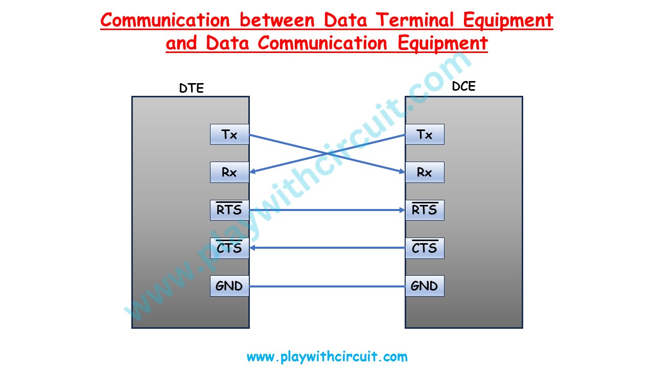
Hardware flow control (also called RTS/CTS flow control), two extra wires are needed in addition to the data lines. They are called RTS (Request to Send) and CTS (Clear to Send). The RS-232 standard defines the signals connecting Data Terminal Equipment (DTE) to Data Communication Equipment (DCE) or from one DTE to another DTE.
When the UART module is configured as a DTE (Data Terminal Equipment) device, UART hardware configures the RTS signal as an output, while the CTS signal is an input. In a DCE (Data Communication Equipment) system, the opposite is true; the RTS signal is an input, while the CTS signal is an output.
The active-low RTS and CTS signals work together to control transmission flow. Hardware flow is typically controlled by the DTE device, which could be considered a ‘master’ device.
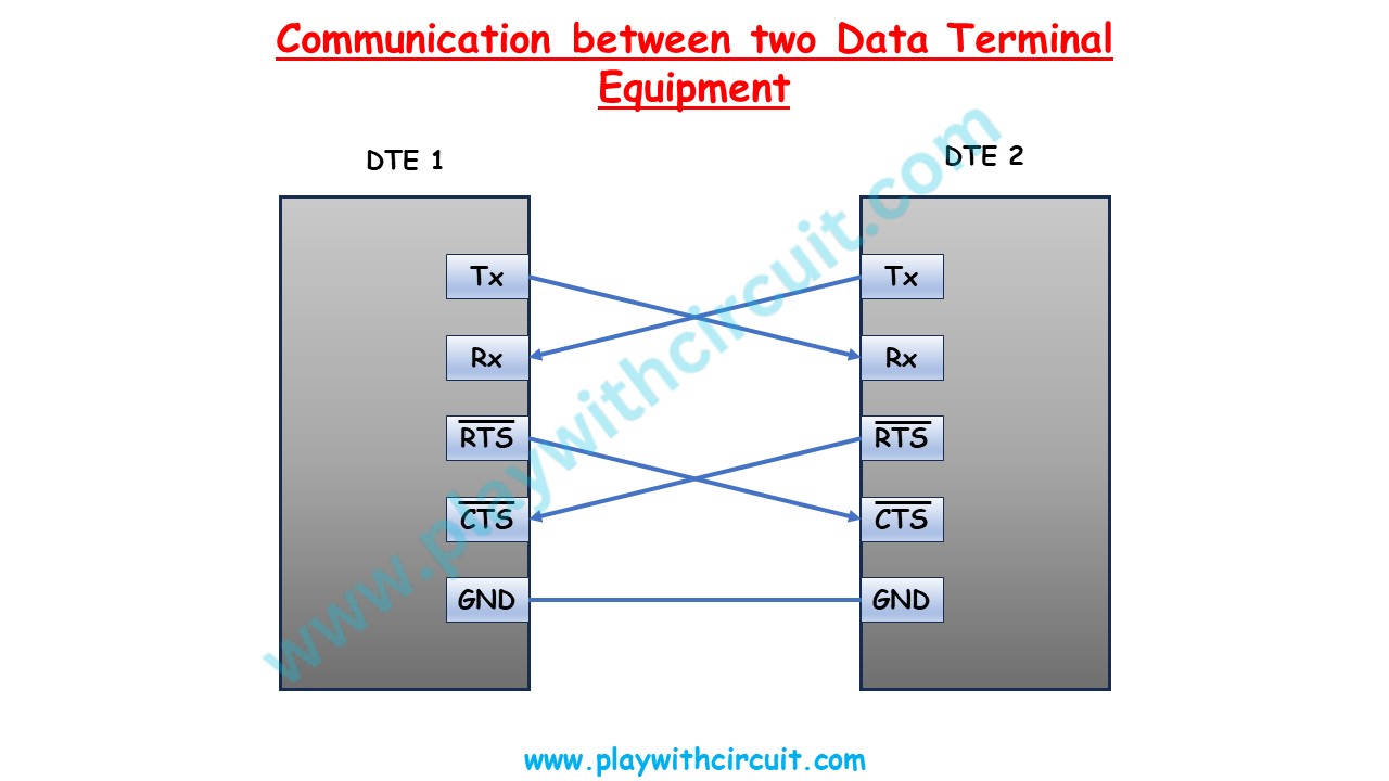
UART Connections Between Two DTE Devices
In the case of a DTE-to-DTE configuration, either device can act as a master. When one DTE device wishes to transmit data, the DTE device pulls the RTS line low, which signals the slave device, through its CTS input, to begin to monitor its RX input. When the slave device is ready to accept the data, it pulls its RTS line low, informing the master, through its CTS line, to begin sending data.
As long as Receiver device is ready to accept more data, it will keep the RTS line LOW. It shall toggle RTS to HIGH some time before its receive buffer is full. The receiver Device gets all data from receive buffer then should pull its RTS line LOW. Once the transaction has completed, the master device pulls the RTS line high.
UART Connections between a DTE Device and DCE Device
In a DTE-to-DCE configuration, the DTE is considered the master and the DCE is considered a slave. In this configuration, when the DTE device wishes to transmit data, the DTE device pulls the RTS line low, which signals the DCE device, through its RTS line, to begin to monitor its RX line. When the DCE device is ready to accept the data, it pulls its CTS line low, informing the DTE device, through its CTS connection, to begin sending data.
Software Flow Control
Software flow control uses the XON/XOFF (Transmit ON/Transmit OFF) method. This method has an advantage over hardware flow control methods since it does not require additional hardware lines, which significantly reduces wiring complexity.
In the XON/XOFF method, special characters are sent by the receiver to the transmitter that are used to suspend and resume transactions. These characters are not specifically defined by any standard, such as ASCII. However, the ASCII standard provides generic ‘device control’ characters, DC1 – DC4. The UART module specifically uses the ASCII control characters DC1 (0x11) and DC3 (0x13) as the XON and XOFF control characters, respectively. If device B sends XOFF to device A it means that A should halt transmission to B until A receives an XON character from B.
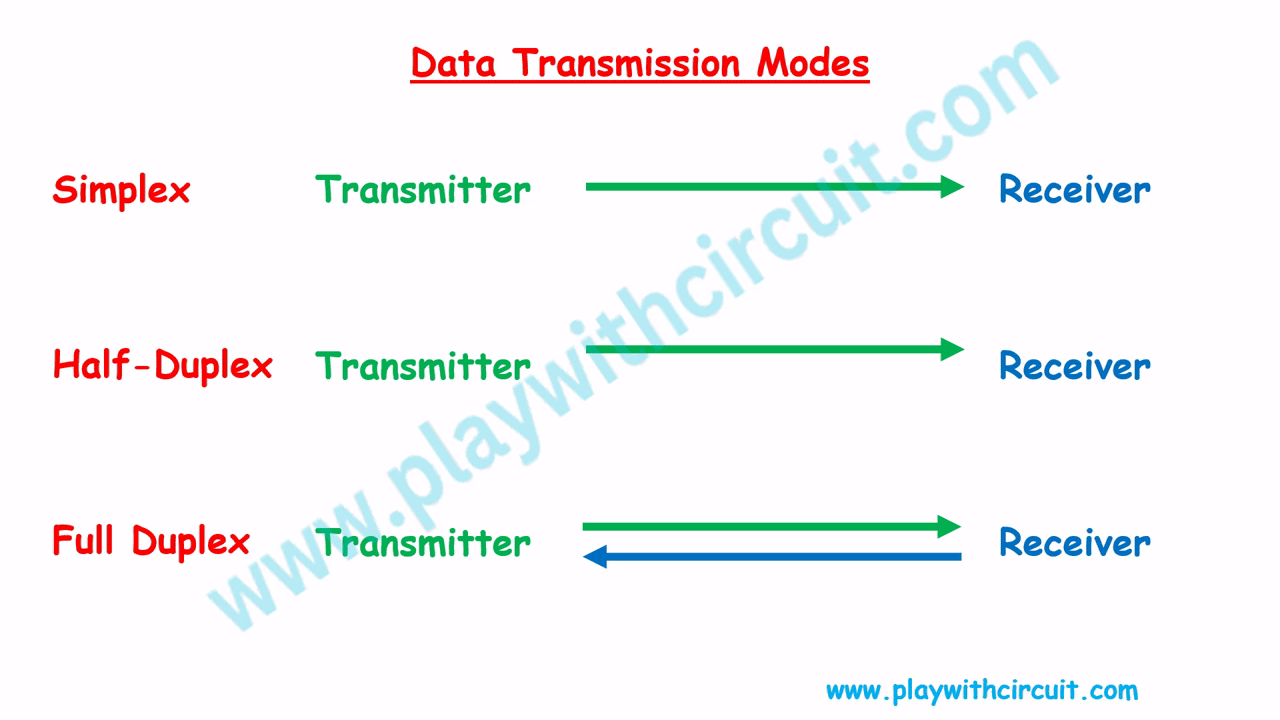
Sending Mode: UART can operate in full-duplex or half-duplex mode. Full-duplex allows simultaneous two-way communication, while half-duplex supports bidirectional communication but not simultaneously.
UART Voltage Levels and Interfacing Standard
So far, we’ve learned how UART works logically. But in real-world applications, UART signals also have to travel across physical wires, and here voltage levels matter. Let’s learn about voltage levels and interfacing standards used in UART communication.
RS232 Standard
The most widely used interfacing standard in older PCs, modems, and industrial equipment is RS-232 set by the Electronics Industries Association (EIA) in 1960.
In RS232, Logic ‘1’ is represented by -3V to -15 V, while Logic ‘0’ is +3V to +15 V, making -3V to +3V undefined.
TTL and RS-232 Voltage Levels
Microcontrollers and most modern ICs use TTL (Transistor–Transistor Logic) voltage levels (0–5 V or 0–3.3 V). RS-232, on the other hand, RS232 uses ± voltages with inverted polarity.
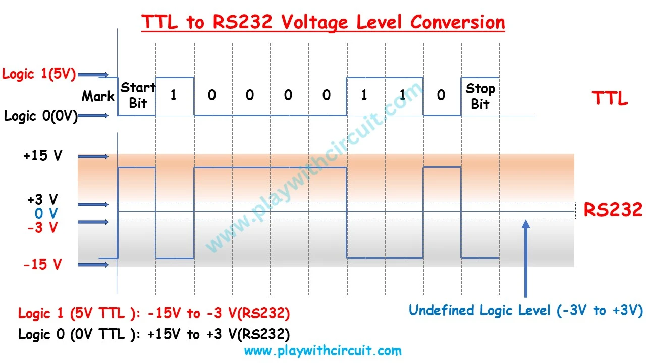
This makes direct connection between a PC’s RS-232 port and a microcontroller impossible without voltage conversion. So a level translator is required to safely connect a microcontroller to a PC or modem. Therefore a level-shifting IC such as MAX232 chip is required to convert RS232 voltage levels to TTL levels, and vice versa.
MAX232 IC Pinout
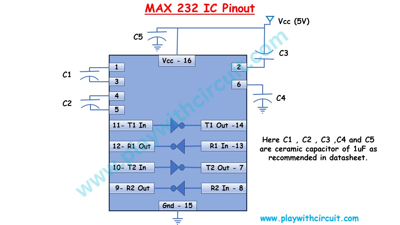
MAX232 IC uses a charge pump with external capacitors to generate the required ± voltages. Below is the pinout of the MAX232, showing its connections for capacitors, transmit (Tx), and receive (Rx) lines.
| Pin Number | Pin Name | Description |
|---|---|---|
| 1 | C1 + | Connects to the one end of first capacitor |
| 2 | V+ | Connects to one end of the third capacitor & other end is connected to Vcc |
| 3 | C1 - | Connects to another end of first capacitor |
| 4 | C2+ | Connects to one end of second capacitor |
| 5 | C2- | Connects to another end of second capacitor |
| 6 | V- | Connects to one end of the fourth capacitor & other end is grounded |
| 7 | T2 OUT | Tx pin of second converter module of MAX-232 IC (DB9 Connector Side) |
| 8 | R2 IN | Rx pin of second converter module of MAX-232 IC (DB9 Connector Side) |
| 9 | R2 OUT | Rx pin of second converter module of MAX-232 IC (Microcontroller Side) |
| 10 | T2 IN | Tx pin of second converter module of MAX-232 IC (Microcontroller Side) |
| 11 | T1 IN | Tx pin of first converter module of MAX-232 IC (Microcontroller Side) |
| 12 | R1 OUT | Rx pin of first converter module of MAX-232 IC (Microcontroller Side) |
| 13 | R1 IN | Rx pin of first converter module of MAX-232 IC (DB9 Connector Side) |
| 14 | T1 OUT | Tx pin of first converter module of MAX-232 IC (DB9 Connector Side) |
| 15 | Ground | Connects to the ground of the circuit |
| 16 | Vcc | Connects to the supply voltage typically +5V |
Now that we’ve seen how the MAX232 handles the voltage conversion, let’s understand how devices physically connect using standard connectors. The most common connector for RS-232 communication is the DB9.
DB9 Connector
It comes in male and female versions and has 9 pins, each with a specific role in transmitting data, controlling flow, or signaling device status. DB9 connectors were widely used in PCs for serial ports, and even though USB has replaced them in modern computers, DB9 remains important in industrial equipment and embedded systems. To interface a microcontroller with such devices, understanding the DB9 pin functions is essential.
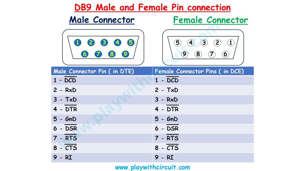
DCD (data carrier detect)
Also known as CD (Carrier Detect). The modem asserts signal DCD to inform the DTE that a valid carrier has been detected and that contact between it and the other modem is established. It is an Active LOW signal and Output Signal from Modem (DCE) and Input to PC(DTE).
RxD(Receive Pin) and TxD(Transmit Pin)
These two pins are used to Receive and transmit the actual data. TxD of DTE is connected to RxD of DCE and TxD of DCE is connected to Rxd of DTE.
DTR (data terminal ready)
When terminal is turned on, it sends out signal DTR to indicate that it is ready for communication. It is an active LOW signal output from DTE and input to modem.
GnD
This is the ground Pin. Gnd of DCE and DTE need to be connected for ground matching.
DSR (data set ready)
When DCE is turned on and has gone through the self-test, it asserts DSR to indicate that it is ready to communicate. It is an Active LOW signal and Output Signal from Modem (DCE) and Input to PC(DTE).
RTS (request to send)
When the DTE device has byte to transmit, it asserts(Pull LOW) RTS to signal the modem (DCE) that it has a byte of data to transmit. It is an active LOW signal output from DTE and input to modem.
CTS (clear to send)
When the modem has enough space in receive buffer for storing the data it is to receive, it sends out signal CTS to DTE to indicate that it can receive the data now. It is an Active LOW signal and Output Signal from Modem (DCE) and Input to PC(DTE). When DTE finds CTS signal LOW. It will transmit the Data.
RI (ring indicator)
An output from the modem and an input to a PC indicates that the telephone is ringing. It goes on and off in synchronous with the ringing sound. It is an Active HIGH signal and Output Signal from Modem (DCE) and Input to PC(DTE). It is used rarely.
UART Wiring Configurations with DB9
Let’s understand how to make Data Terminal Equipment and Data Communication Equipment and connecting two DTE devices together.
Wiring a Data Terminal Equipment

When we want to make a data terminal equipment then generally, we will be needing a microcontroller, a MAX 232 IC and DB9 male connector.
TxD of controller will be connected to any of the Tx In pin of Max232 here we have connected to pin 11 and RxD of the microcontroller will be connected to any of the Rx Out pin of Max 232 IC here it is connected to pin 12. Now pin 14 is connected to pin 3 of the DB9 male connector as it is the Tx Pin and Pin 13 is connected to the pin 2 of the DB9 female pin as it is the Receiver pin of the connector.
Wiring a Data Communication Equipment
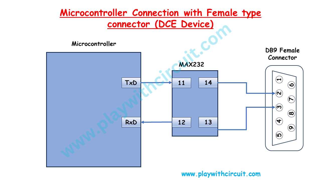
When we want to make data communication equipment, let’s say a modem using Sim 800 module then generally, we will be needing a module, a MAX 232 IC and DB9 male connector.
TxD of controller will be connected to any of the Tx In pin of Max232 here we have connected to pin 11 and RxD of the microcontroller will be connected to any of the Rx Out pin of Max 232 IC here it is connected to pin 12. Now pin 14 is connected to pin 2 of the DB9 female connector as it is the Tx Pin and Pin 13 is connected to pin 3 of the DB9 female pin as it is the Receiver pin of the Connector.
Null Modem Connection
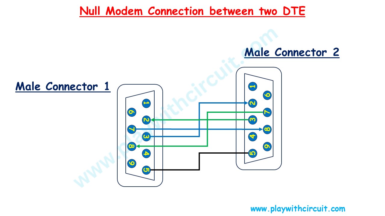
A null modem connection is required when we want to connect two DTE together. In above figure two male DB9 connectors are shown for two DTE. Pin 2 of one DTE is connected to Pin 3 of another DTE also Pin 7 and Pin 8 (RTS and CTS) of the two DTE’s are crossed.
To make a null modem connection cable we will be needing two DB9 female connectors with above connections, don’t forget to connect the ground wire.