
8051 microcontroller is the most widely used micro-controller and also one of the easiest microcontrollers to understand. In this article, we will learn about basic general-purpose input-output pin programming of 8051 microcontroller.
8051 consists of 40 pins out of which 32 pins can be used for general input output purpose and remaining 8 pins serve special purposes.
These 32 pins are subdivided in 4 ports. All pins of all 4 ports can be used for input/output but there are some pins which can be used for special purposes.
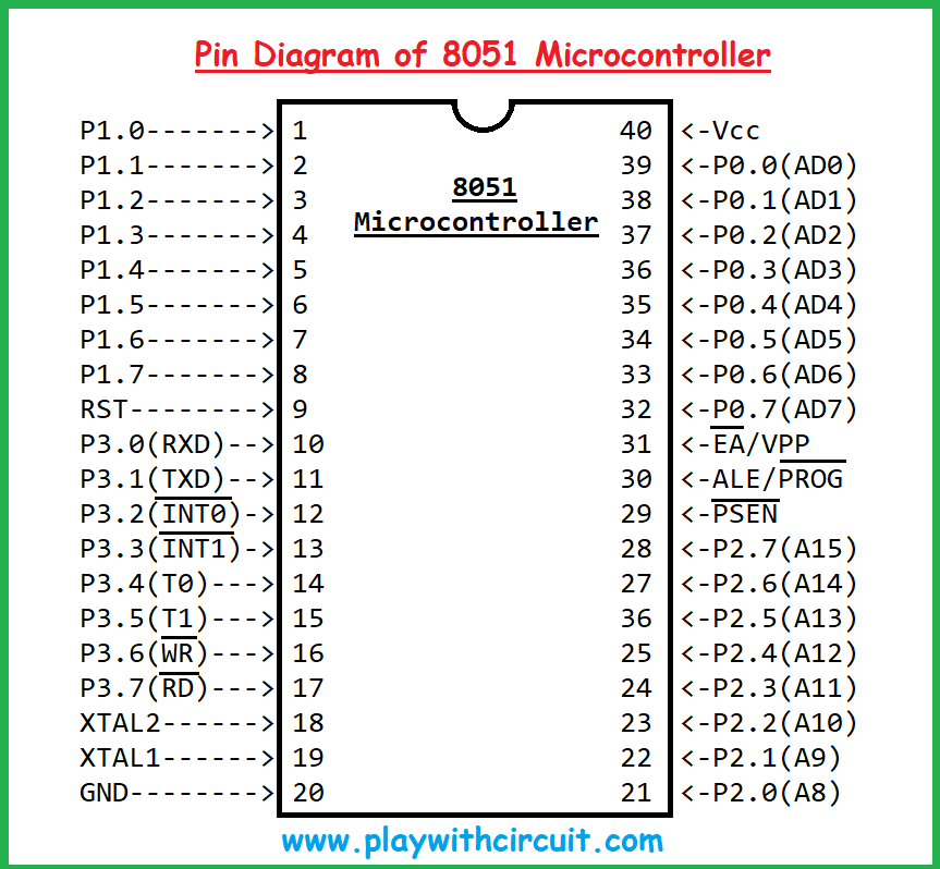
Pin Diagram of 8051 Microcontroller
In the below image we can see there are four ports P0, P1, P2 and P3 out of which P1, P2 and P3 are internally pulled up and port P0 is open drain. Hence to work with P0 we need external pull-up circuitry.
Here we will learn how we can program these pins to work as general-purpose Input/Output pins. Also, we will be learning about basic support circuitry which is used to run programs on 8051 microcontrollers.
There are many passive components other than power supply and crystal oscillator which should be connected to 8051 to run code on it.
We will learn about Reset circuitry which is required to reset a microcontroller when it’s turned ON.
Talking about coding perspective we will learn
- How to make a pin working as Output pin
- How to make a pin working as Input pin
- If the pin becomes input, then check status using the polling method.
- To work with External Hardware Interrupts as well.
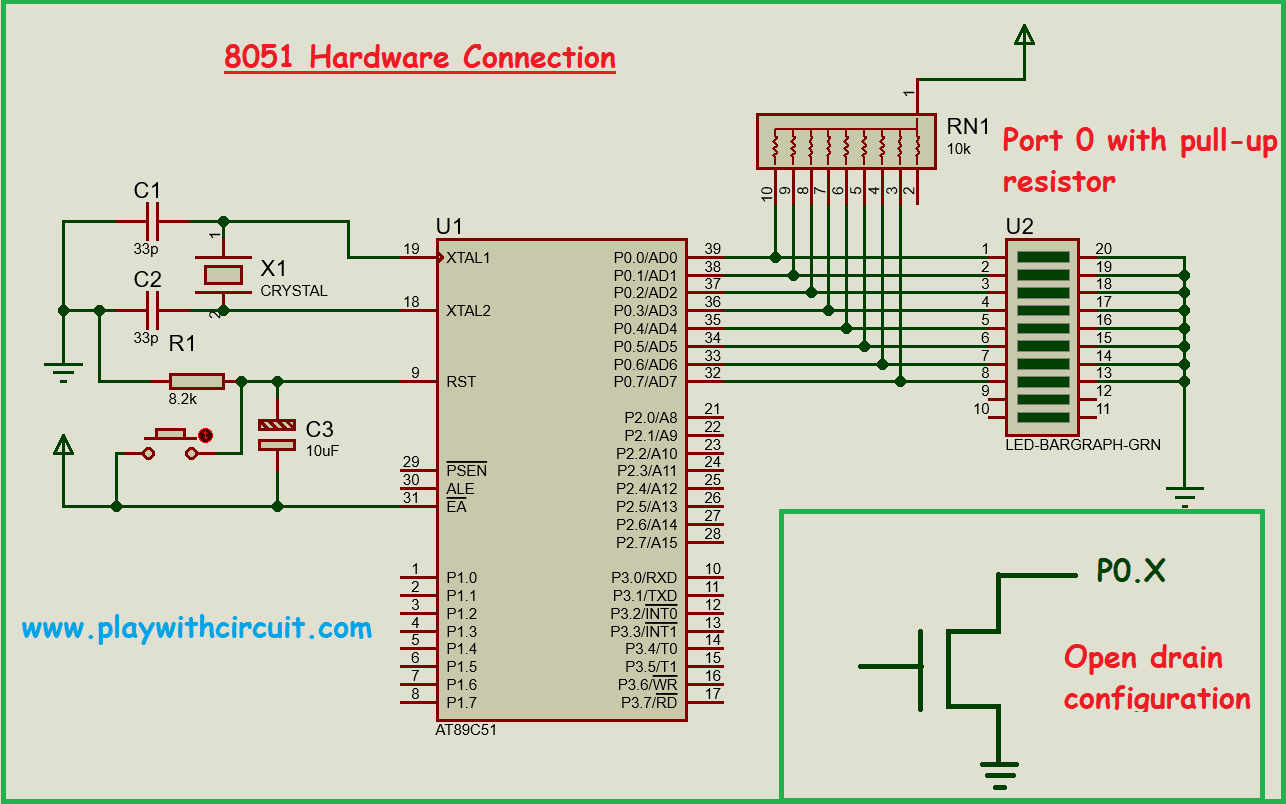
8051 Hardware connection Circuit
In the image below we can see an 8051 IC which is connected to various components.
-
Timing Circuitry consists of one Crystal oscillator – X1 is connected at pin 19 and pin 18 which is connected to capacitor C1 and C2. Every typical 8051 controller needs external crystal Oscillator to provide Clock pulses to run the microcontroller.
-
Reset Circuitry consists of Capacitor C3 and Resistance R1 along with a reset button. This type of circuit resets the microcontroller when power is turned ON as well as pressing the button which is connected parallel to capacitor C3.
-
Port 0 is connected with an LED bar and is pulled up using network resistor RN1.
-
Pin 40 connected to 5V and Pin 20 Connected to Ground (Not shown in hardware connection diagram)
List of Components to Run 8051 IC
- Crystal oscillator X1: 11.0593Mhz
- Ceramic capacitors C1 and C2: 33pf
- Electrolytic capacitor C3: 10uf
- Resistance R1: 8.2k-ohm
- Push button.
How to Code
After reset of 8051 microcontroller all pins behave as input pins.
To make a output pin 0(zero) is to be written to that pin.
Requirement 1:
Now let’s say we have a requirement to write a program to glow LED using Pin P0.0 and it will toggle its state when the button is pressed which is connected at pin P3.2 using polling method.
Code Design:
Firstly, make pin P0.0 as output pin we need to write statement in ‘Embedded C’
P0.0 = 0;
Make pin P3.2 as input pin we need to write
P3.2 = 1;
We will be connected one end of button with pin P3.2 and another end with Ground. Now we need to write code if P3.2 pin gets grounded then toggle the state of pin P0.0 pin.
If (P3.2 == 0)
{
P0.0 = ~P0.0; // this is toggling of pin
}
Requirement 2:
Now let’s say we have a requirement to write a program to glow an LED using Pin P0.0 and it will toggle its state when the button is pressed which is connected at pin P3.2 using an interrupt method.
Code Design:
In this code we first initialize the Pin P0.0 as output pin and Pin P3.2 as Input pin.
Our input pin P3.2 is also INT0 pin that is why we are using the same pin in both the codes so that hardware connection will be same for both requirements.
P0.0 = 0;
P3.2 = 1;
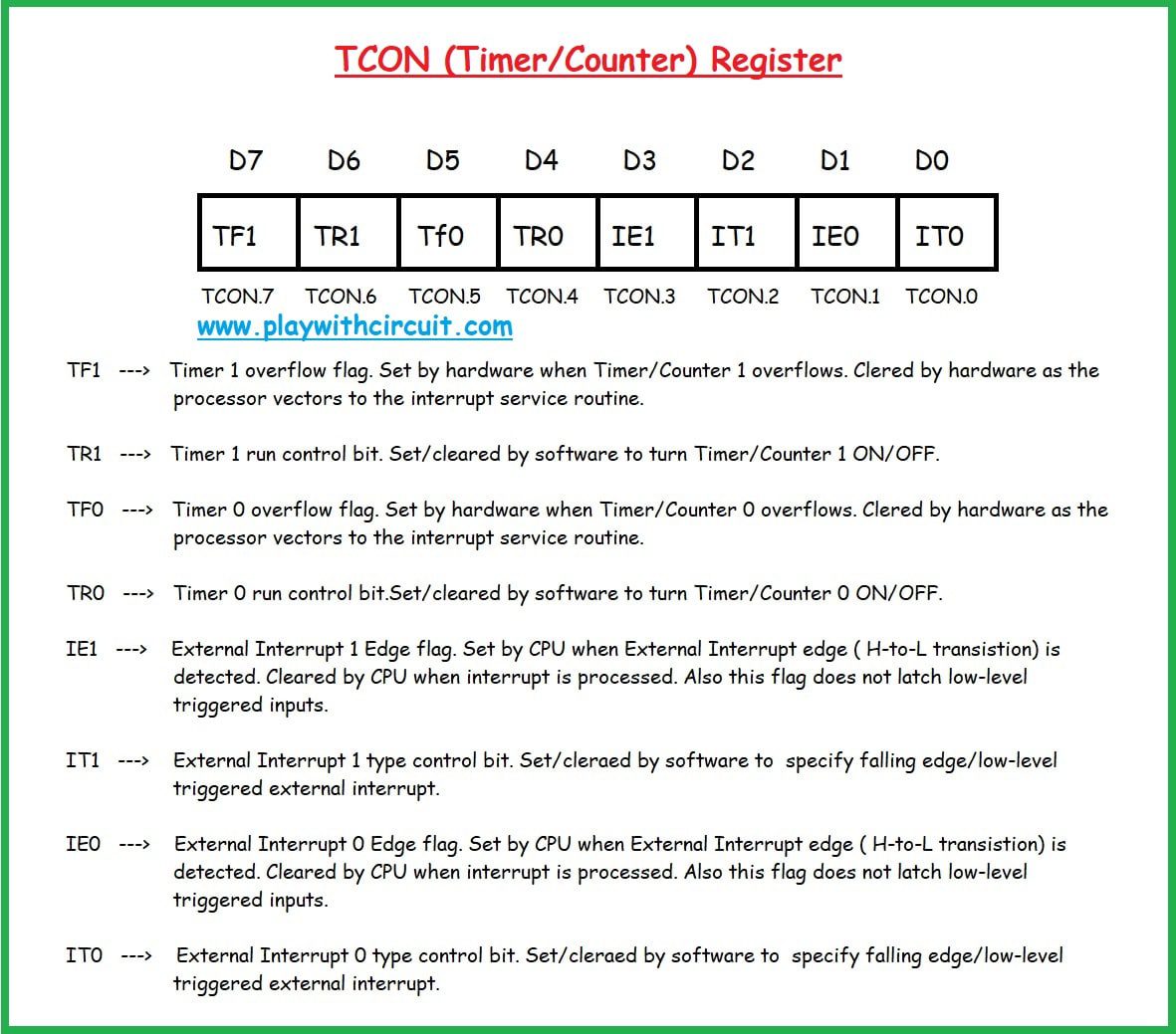
In the image below we can see image of TCON (Timer /Counter) register. This register is also used for External hardware interrupt settings using IT0 bit.
This register is bit addressable hence we can also set one bit at a time.
Using the TCON register one setting need to be done when to enable Interrupt. Before actually Enabling External Hardware interrupt on pin P3.2.
So, the question is:
Is it a low level triggered interrupt (i.e., generate interrupt when pin is low) or Edge triggered interrupt that is when High to Low edge is detected. This setting is done by setting IT0 pin of TCON register.
When IT0 pin in this register is 1 then its Edge triggered interrupt else it will be level triggered interrupt.
In this code we will set this pin to Enable interrupt only when High to Low transition occurs at INT0 pin P3.2.
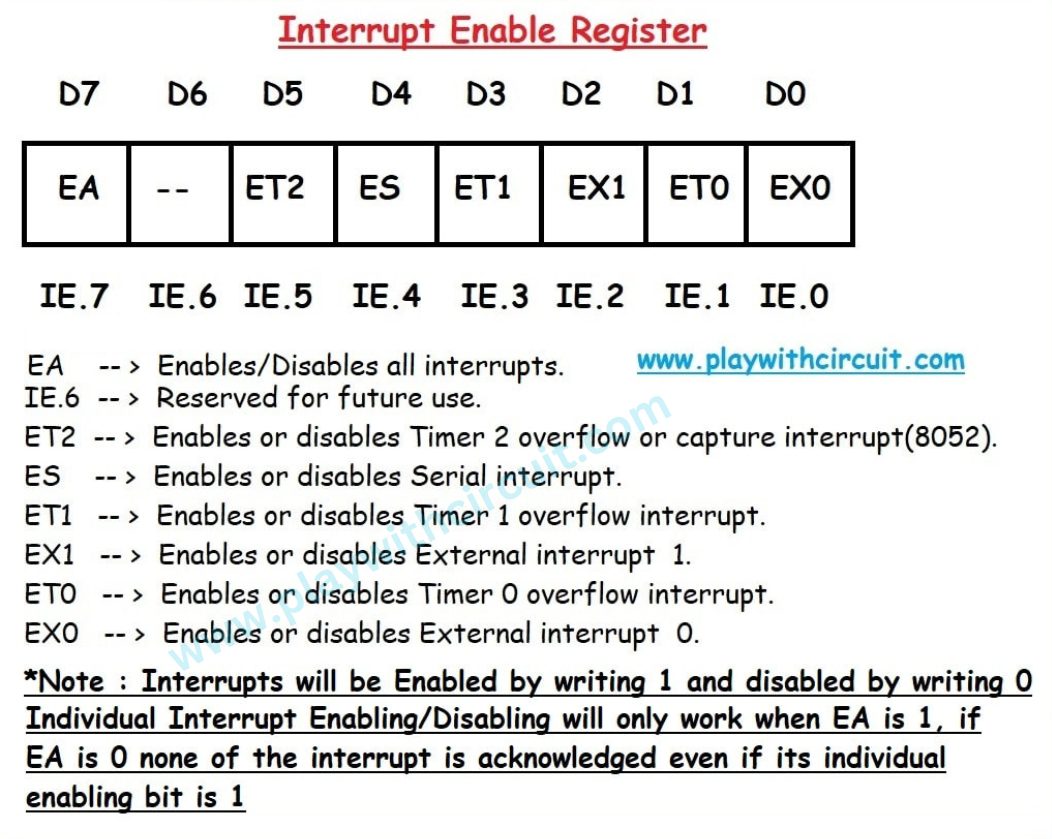
To Enable External Hardware Interrupt at Pin P3.2 EX0 bit should be set to 1 in Interrupt Enable register which is also bit addressable.
After that we need to enable all interrupts using EA pin of Interrupt Enable Register. In the following image we can see that EA pin is the seventh pin of Interrupt Enable Register.
Hence our coding sequence will be like this
IT0 = 1;
EX0 = 1;
EA = 1;
After Doing this we need to write ISR i.e., Interrupt service Routine code for External Hardware Interrupt 0.
Interrupt Vector Table: Whenever any Interrupt occurs then CPU searches for address of IRS inside Interrupt Vector Table. After getting the address of ISR it executes ISR and at the end of ISR there is this RETI (return from interrupt) instruction. This instruction is implicit and, in this instruction, flag due to which ISR is run, is cleared automatically (for most of interrupts except serial) and then CPU returns to the place where it was interrupted. Below is the ISR table along with the priority and its ISR address.
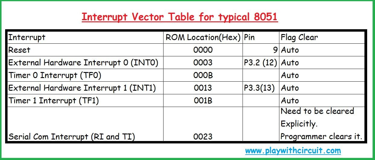
Here “vInt0Interrupt” this is the ISR name and “interrupt 0” written after it ensures that its address is 0003H. It is to be written in this way only.
“RETI” not required explicitly in ‘Embedded C’ as its automatically added in Assembly conversion.
void vInt0Interrupt(void) interrupt 0
{
// Need to write code for toggling of P0.0 pin
P0.0 = ~P0.0;
}
So this is all about how to use input output functionality of 8051 microcontroller. Input port of 8051 microcontroller can be used to get input from external peripheral devices like keypad, push buttons, LDR, sensors and so on. These ports can also be connected to LCD displays, Seven Segment Displays, LED Matrix, Relays, Transistors, etc.