
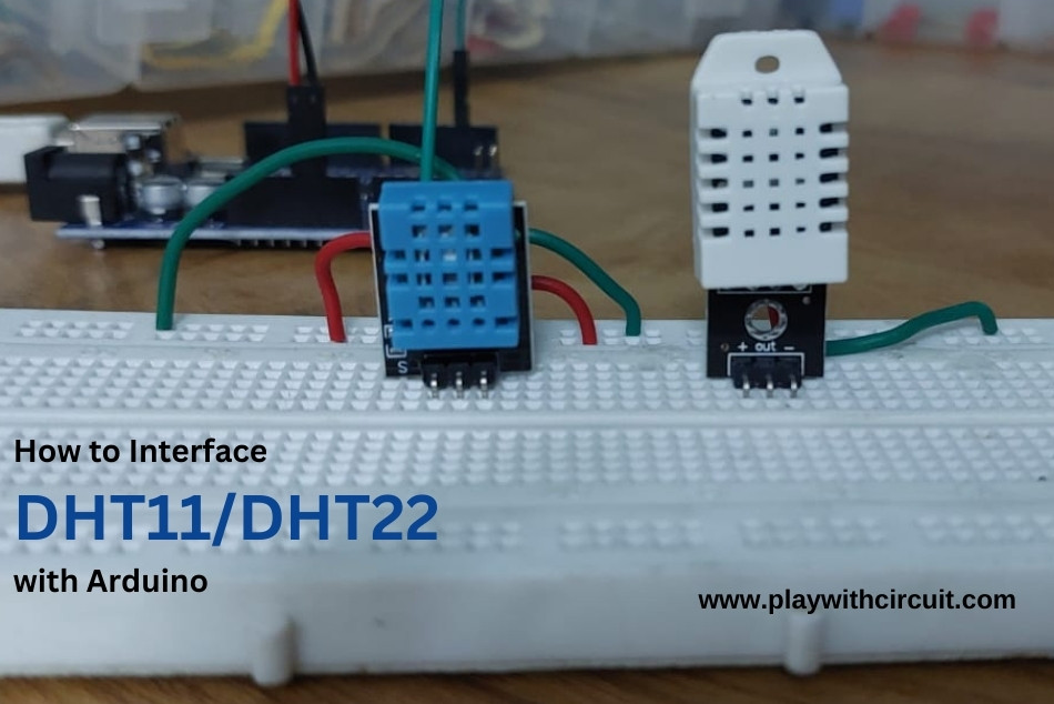
Want to create a smart home climate control system, build a plant monitoring system or measure real-time temperature and humidity data in a weather station? DHT11 or DHT22 Temperature and Humidity Sensor can be the ideal choice. Their ease of use, affordability, and relatively accurate readings make them well-suited for DIY Electronics projects where climate data is required.
These sensors can be easily interfaced with Arduino to measure humidity and temperature. With a simple setup involving just a few connections and some Arduino code, you can start capturing accurate humidity and temperature data instantaneously.
In this tutorial, we will learn about DHT11 and DHT22 sensors, and how to use them for measuring temperature and humidity with the Arduino board.
Overview of DHT11 and DHT22 Sensor
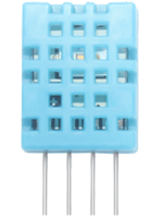
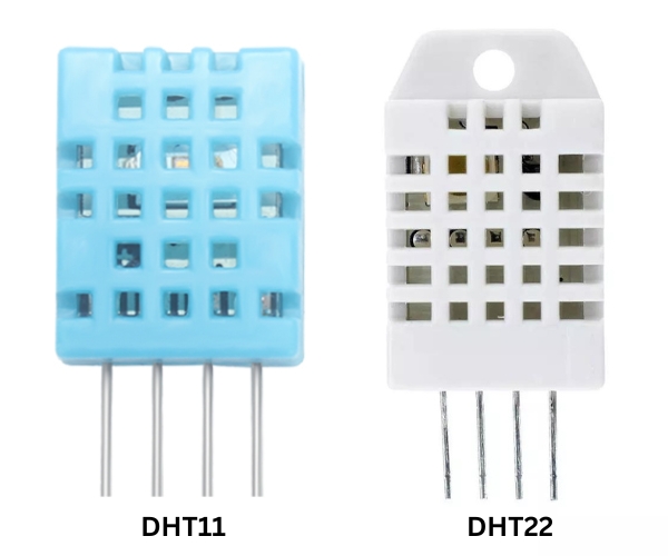
The DHT11 and DHT22 are both popular temperature and humidity sensors in the DHTxx series. They look similar and have the same pinouts, but differ in terms of their specifications, accuracy, and capabilities.
Starting with the DHT11, it is a more basic and cost-effective sensor compared to the DHT22. DHT11 is suitable for basic applications where high precision is not critical. It has a temperature measurement range of 0-50°C with an accuracy of ±2°C and humidity measurement range of 20-90% with an accuracy of ±5%.
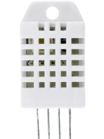
On the other hand, the DHT22 is a more advanced and accurate sensor. It offers a wider measurement range for both humidity and temperature, making it suitable for a broader range of applications. The DHT22 has a humidity measurement range of 0-100% with an accuracy of ±2 to ±5%, depending on the specific model, and a temperature measurement range of -40 to 80°C with an accuracy of ±0.5°C. This enhanced accuracy and extended range make the DHT22 a preferred choice for applications where precise climate monitoring is crucial.
Specifications
| DHT 11 | DHT 22 | |
|---|---|---|
 |  |
|
| Temperature Range | 0 to 50°C | -40 to 80°C |
| Humidity Range | 20-90%RH | 0-100%RH |
| Accuracy | ±2°C for temperature, ±5%RH for humidity | <±0.5°C for temperature, ±2 to ±5%RH for humidity |
| Sampling Rate | 2 seconds | greater than 2 seconds |
| Operating Voltage | 3.3 to 5.5V DC | 3.3V to 6V DC |
| Max Operating Current | 1.5mA | 1.5mA |
| Resolution or sensitivity | humidity 1%RH; temperature 1°C | humidity 0.1%RH; temperature 0.1°C |
| Repeatability | humidity ±2%RH; temperature ±1°C | humidity ±1%RH; temperature ±0.2°C |
| Sensing element | Polymer humidity resistor | Polymer capacitor |
While the DHT22 has superior accuracy, precision, and a broader operational range for temperature and humidity measurements, the DHT11 excels in terms of affordability and compact size.
The best part is that DHT11 and DHT22 sensors are interchangeable, allowing you to easily switch between sensors based on changing project requirements without the need for extensive hardware modifications. The code needs to be modified a little, but the wiring configuration remains the same.
This flexibility allows you to easily switch between these sensors based on your specific requirements without having to make significant changes to your setup.
The choice between these sensors depends on the specific needs of a project, with the DHT11 being a cost-effective solution for less demanding applications and the DHT22 offering higher precision for more critical projects.
DHT11 / DHT22 Working Principle
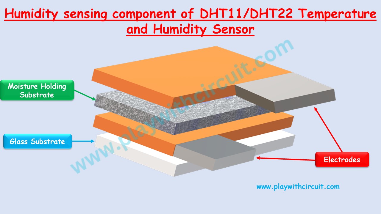
They consist of a humidity-sensing component, a Negative Temperature Coefficient (NTC) thermistor, and an IC.
For measuring humidity, sensors use a humidity-sensing component which has two electrodes separated by a moisture-holding substrate. This substrate’s conductivity changes when humidity changes, thereby altering the resistance between the electrodes. This change in Resistance is sensed by the internal MCU of the sensor. The internal MCU of the sensor processes it and sends relative humidity over the data pin.
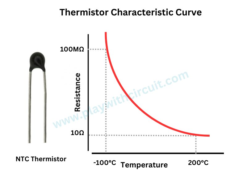
The sensors utilize the NTC Temperature Sensor or thermistor to measure temperature. The thermistor changes its resistance with temperature variations, allowing the sensor to determine the ambient temperature by measuring this resistance. The resistance of a thermistor is highly temperature-dependent. “NTC” stands for “Negative Temperature Coefficient,” indicating that these thermistors exhibit a decrease in resistance as the temperature increases.
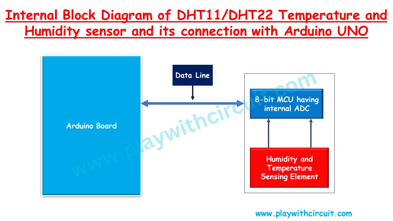
The sensors also have an 8-bit SOIC-14 packaged Integrated Circuit (IC) which measures and processes the analog signal generated by the thermistor and humidity-sensing component. It converts the analog signal into a digital and outputs a digital signal that includes temperature and humidity readings.
How DHT11 Sensor Communicate with Arduino using Aosong One wire protocol
Arduino communicates with the DHT11 sensor using 1-wire protocol. The communication process is divided in three steps, first is to send a start signal to DHT11 sensor, then the sensor will send a response pulse and then it starts sending data of a total 40 bits to the microcontroller.
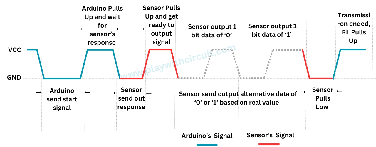
When the microcontroller unit (MCU) of Arduino sends a start signal, the DHT11 transitions from standby status to running status. The start signal is a logical LOW for 18 milliseconds followed by a low to high transition.
Upon completion of sending the start signal by the MCU, the DHT11 transmits a response signal followed by 40 bits of data representing relative humidity and temperature back to the MCU. The response pulse is a logical LOW of 80 microseconds followed by a logical HIGH of 80 microseconds. Without the start signal from the MCU, the DHT11 does not provide a response signal. Each response data from the DHT11, reflecting relative humidity and temperature, corresponds to one start signal from the MCU. After completing data collection, the DHT11 returns to standby status if it does not receive another start signal from the MCU.
Sending the Start Signal
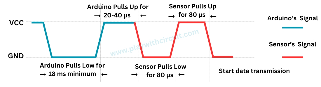
The idle state of the data bus is at a high voltage level. When communication initiates between the MCU and DHT11, the MCU pulls the data bus low, ensuring a duration of at least 18 ms to allow the DHT11 to detect the MCU’s signal. Subsequently, the MCU releases the bus and waits for 20-40 µs for the DHT11’s response. Upon detecting the start signal, the DHT11 pulls the bus low for 80 µs as a response signal and then prepares to send data by pulling the bus high for 80 µs.
Receiving the Data
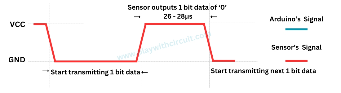
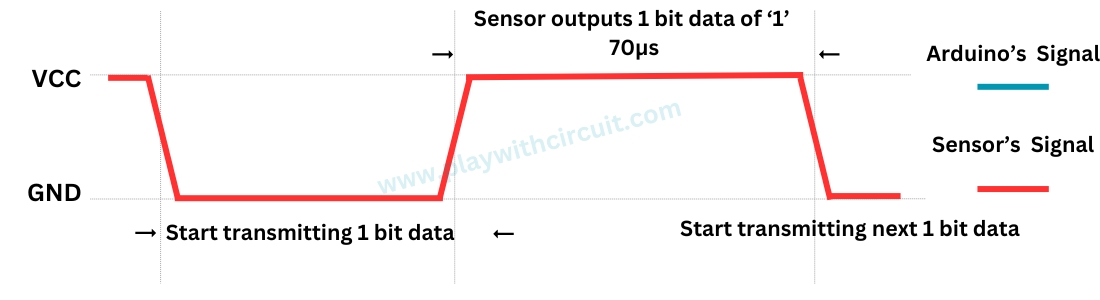
During data transmission from the DHT11 to the MCU, each bit’s transmission starts with a low-voltage-level signal lasting 50us. The subsequent high-voltage-level signal’s duration determines whether the bit represents a “1” or a “0”.
When the High pulse time in the single bit is 26 to 28 microseconds then it means bit 0 is received.
When the High pulse time in the single bit is near 70 microseconds then it means bit 1 is received.
❕Note
If the signal from the DHT11 consistently remains at a high-voltage level, it indicates that the DHT11 may not be functioning correctly. Please verify the electrical connection status.
Understanding the Data Received
While sending the data the DHT11 sensor sends MSB(Most Significant Bit) first. A total of 40 bits are sent, which means Arduino receives 5 bytes of data in MSB first manner.
Consider the data received from the DHT11 Sensor is
00100001 00000000 00011010 00000000 00111011.
This data can be formatted as follows:
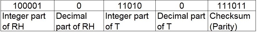
The First Byte from the left the “0010 0001” is received first. In this byte its Most Significant Bit(MSB) is received first i.e. ‘0’ and Least Significant Bit(LSB) in the end i.e, ‘1’. This byte is followed by the second, third, fourth, and fifth byte.
- First byte: Integer part of Relative Humidity
- Second byte: Decimal part of related Humidity.
- Third byte: Integer part of Temperature in degrees Celsius.
- Fourth byte: Decimal part of Temperature in degrees Celsius.
- Fifth byte: It is the checksum byte which should be equal to the sum of all bytes. If the sum overflows 8 bits then only lower byte of sum is considered as checksum byte, higher byte is ignored.
In order to verify that the received data is correct or not, we can perform a small calculation. Check if the sum of the integral and decimal values of RH and Temperature equals the checksum value, i.e. the last 8-bit data.
Sum = 00100001 + 00000000 + 00011010 + 00000000=00111011
Checksum = the last 8 bits of Sum = 00111011.
It is evident from the above that the data obtained is correct. Now, simply convert the binary data to decimal data to obtain the RH and Temperature values.
RH = Decimal of 00100001 = 33%
Temperature = Decimal of 00011010 = 26°C
DHT11 and DHT22 Pinout
The DHT11 and DHT22 have similar pinouts. The following image provides a general overview of their pin configurations: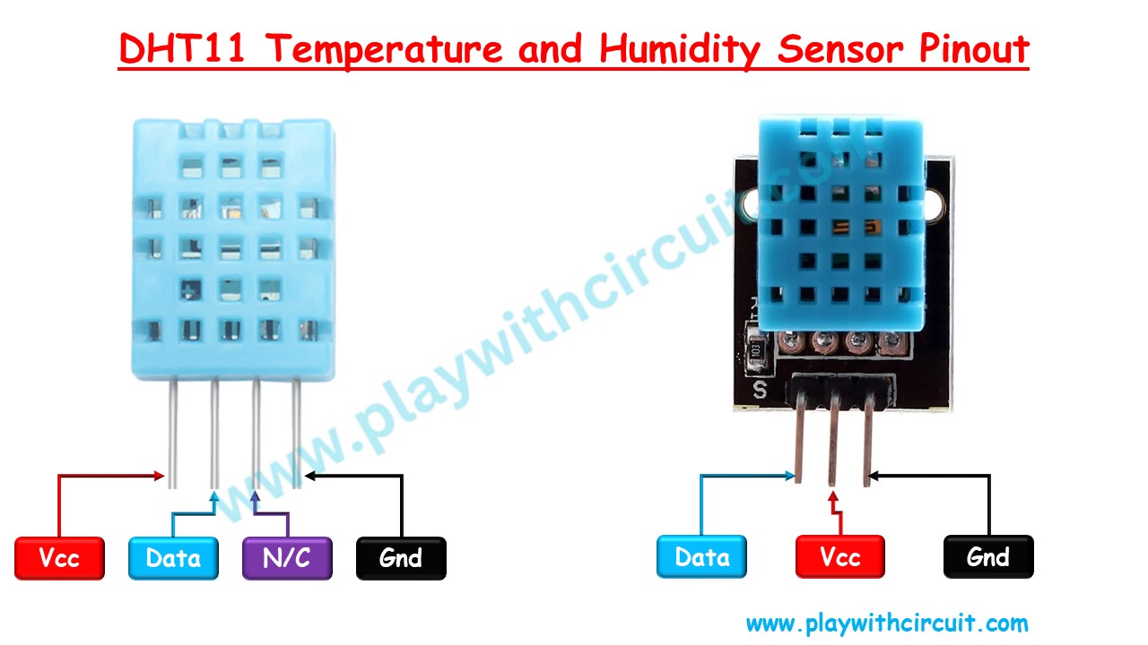
VccThis pin provides the power supply for the sensor. It typically operates within a voltage range of 3.3 to 5.5 volts.
DataThis pin is used for communication between the sensor and the microcontroller.
N/CNot Connected
GndThis pin should be connected to the ground of the microcontroller.
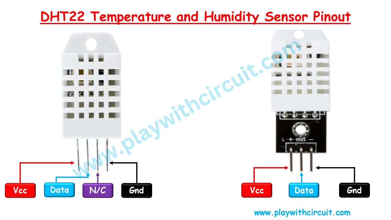
VccThis pin provides the power supply for the sensor. It typically operates within a voltage range of 3.3 to 6 volts.
DataThis pin is used for communication between the sensor and the microcontroller.
N/CNot Connected
GndThis pin should be connected to the ground of the microcontroller.
To know more download the datasheets of DHT11 and DHT22 sensor.
❕Note
In the above diagrams the pinout of the raw sensor and the PCB assembly package is shown. The pinout will be the same for DHT11/DHT22 sensors as it is decided by the manufacturer, but the assembly package pinout may differ hence check with the multimeter before doing the connections.
Interfacing DHT11 and DHT22 Sensors to an Arduino
In this section we will be interfacing an Arduino UNO with the DHT11 and DHT22 temperature sensor.
Hardware and Software Requirements
Hardware
Software
- Arduino IDE, Version 2.1.1 or above installed on your PC
- DHT Sensor Library by Adafruit, Version 1.4.6 installed in Arduino IDE
Wiring Diagram
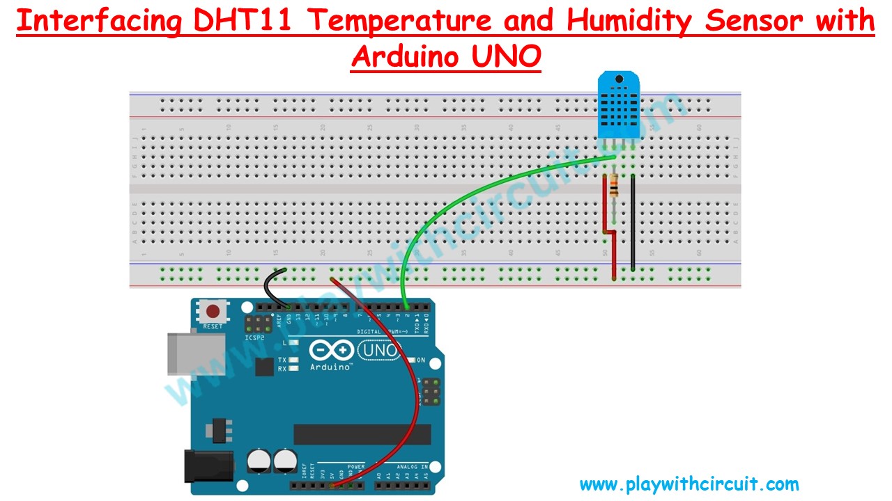
In the above wiring diagram, we can see a DHT11 temperature and humidity sensor connection with the Arduino UNO. The first pin of the sensor from the left is the power pin which is connected to the Vcc of the Arduino UNO. Second is the data pin which is connected to pin2 of Arduino. This pin has been externally pulled up using 10k resistance. The third pin is not connected and the fourth pin is connected to the ground pin of the Arduino.
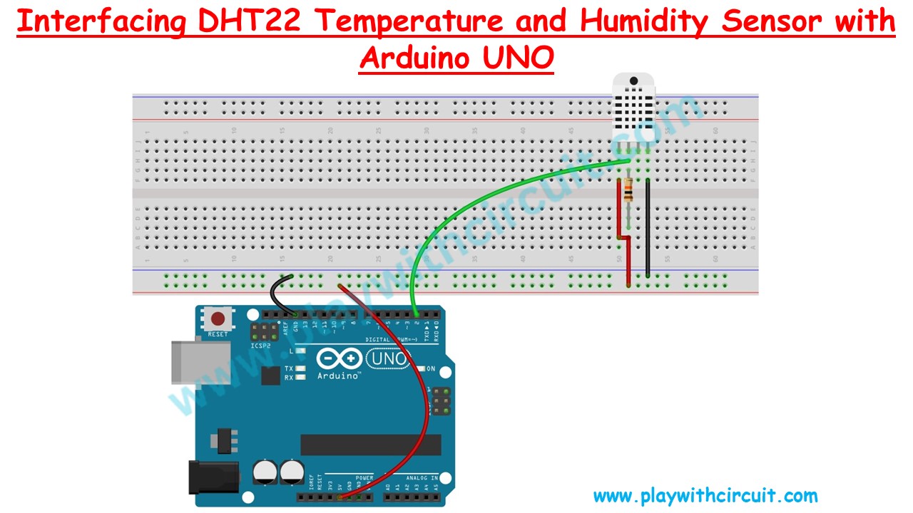
The DHT11 and DHT22 both the sensors are pin compatible. The 1 wire protocol for DHT11 , DHT22 is approximately the same with minor differences. Hence the wiring diagram remains the same. There will be a few changes in the code, which we will discuss while coding.
Arduino Example Code 1
In the below code, we will be interfacing a DHT11/DHT22 temperature and humidity sensor with Arduino UNO. We will be getting data on the Serial UART terminal in the Arduino IDE. We will be using the DHT Sensor Library by Adafruit.
Code
/*
this code is brought to you by www.playwithcircuit.com
*/

#include <DHT.h>

#define DHTPIN 2       // Define the digital pin where the DHT sensor is connected
#define DHTTYPE DHT11  // DHT11 or DHT22, change this according to your sensor type

DHT dht(DHTPIN, DHTTYPE);

void setup() {
  Serial.begin(9600);  // initialize serial port
  dht.begin();  // Initialize the DHT sensor
}

void loop() {
  // Read temperature and humidity from the DHT sensor
  // In the parameter pass true if temperature is required in fahrenheit, pass false if temperature is required in celsius
  float temperature = dht.readTemperature(false);
  float humidity = dht.readHumidity();

  // Check if the sensor reading is valid (non-NaN)
  if (!isnan(temperature) && !isnan(humidity)) {
    Serial.print("Temperature: ");
    Serial.print(temperature);
    Serial.print(" °C, Humidity: ");
    Serial.print(humidity);
    Serial.println("%");
  }
  else
  {
    Serial.println("Failed to read from DHT sensor!");
  }
  delay(2000);  // Delay for 2 seconds before the next reading
}
Code Explanation
In this code firstly we will include the header file of the DHT library and Make pin 2 the sensor data pin.
In the setup() function, we will initialize the serial port and the DHT sensor.
In the loop() function we use dht.readTemperature() and dht.readHumidity() to get the temperature and Relative humidity respectively. After checking the validity of the response data is sent on the serial bus.
Output:
Temperature: 28 °C, Humidity: 46%
Temperature: 28 °C, Humidity: 46%
Temperature: 28 °C, Humidity: 46%
Temperature: 28 °C, Humidity: 46%
Temperature: 28 °C, Humidity: 46%
Temperature: 28 °C, Humidity: 46%
Temperature: 28 °C, Humidity: 46%
Temperature: 28 °C, Humidity: 46%
Temperature: 28 °C, Humidity: 46%
Temperature: 28 °C, Humidity: 46%
Temperature: 28 °C, Humidity: 46%
Temperature: 28 °C, Humidity: 46%
Temperature: 28 °C, Humidity: 46%
Temperature: 28 °C, Humidity: 46%
Temperature: 28 °C, Humidity: 46%
Temperature: 28 °C, Humidity: 46%
Temperature: 28 °C, Humidity: 46%
Temperature: 28 °C, Humidity: 46%
Temperature: 28 °C, Humidity: 46%
Temperature: 28 °C, Humidity: 46%
Temperature: 28 °C, Humidity: 46%
Temperature: 28 °C, Humidity: 46%
Temperature: 28 °C, Humidity: 46%
Temperature: 28 °C, Humidity: 46%
Temperature: 28 °C, Humidity: 46%
Arduino Example Code 2
In the below code, we will be interfacing a DHT11 temperature and humidity sensor with Arduino UNO. We will be getting data on the Serial UART terminal in the Arduino IDE. We will not use any library but we will communicate directly to the sensor using the 1-wire protocol of the DHT sensor. In the previous code, the library is communicating with the sensor and giving us the temperature and humidity value but this time we will make our driver function for getting the data.
Code
/*
this code is brought to you by www.playwithcircuit.com
This code is written to directly communicate with the DHT11 sensor using 1 wire protocol without using any library
*/

#define MAXULONG 4294967295UL
#define TIMEOUT  1000000       // it is in microseconds it is equal to 1 second
// To find the difference between previous time X and Current time Y.
#define DIFFERENCE(X,Y)   ((Y > X)?(Y - X):(MAXULONG - X + Y))

#define DHTPIN 2               // Digital pin connected to the DHT sensor

unsigned long duration;        // Duration of the input pulse in microseconds
unsigned long previous_tick;   // To store previous tick of micros() function.
unsigned long current_tick;    // To store current tick of micros() function.
bool timeout = false;         // To store if Timeout has occurred or not
uint8_t data[5];

void setup() {
  Serial.begin(9600);
}

void loop() {
  while(1)
  {
    // To Request sample
    // Send the start pulse and wait for Sensor's acknowledgment
    pinMode(DHTPIN, OUTPUT);
    digitalWrite(DHTPIN, LOW);
    delay(18);
    digitalWrite(DHTPIN, HIGH);
    delayMicroseconds(40);
    pinMode(DHTPIN, INPUT);

    // Wait for DHT to respond in LOW pulse
    previous_tick = micros();
    do{
      current_tick =  micros();
      if(DIFFERENCE(previous_tick,current_tick) > TIMEOUT)
      {
        timeout = true;
        break;
      }
    }while (digitalRead(DHTPIN) == LOW);

    if(timeout == true){
      Serial.println("\nDHT Low Pulse timeout Error!");
      break;
    }

    // Wait for DHT to respond in HIGH pulse
    previous_tick = micros();
    do{
      current_tick =  micros();
      if(DIFFERENCE(previous_tick,current_tick) > TIMEOUT)
      {
        timeout = true;
        break;
      }
    }while (digitalRead(DHTPIN) == HIGH);

    if(timeout == true){
      Serial.println("\nDHT High Pulse timeout Error!");
      break;
    }

    // clear data array
    memset (data, 0x00,5);
    // Read Actual data from sensor
    for (int i = 0; i < 5; ++i) {
      data[i] = readByte();
      // check if the byte receive is error byte filled
      // do not check checksum byte it could be 0xFF
      if( i != 4 ){
        // do not read further data
        if(data[i] == 0xFF){
          break;
        }
      }
    }

    // check if checksum is OK then only proceed
    if ((data[4] == (data[0] + data[1] + data[2] + data[3])) && (data[4] != 0))
    {
      // Calculate humidity and temperature
      int humidity = data[0];
      int temperature = data[2];

      // Print humidity and temperature
      Serial.print("Temperature: ");
      Serial.print(temperature);
      Serial.print(" °C, Humidity: ");
      Serial.print(humidity);
      Serial.println("%");
    }
    else
    {
      Serial.println("\nDHT Incorrect data Error!");
    }
    break;
  }
  timeout = false;
  delay(2000);            // Delay before taking next reading
}

uint8_t readByte() {
  uint8_t result = 0;
  unsigned long startTime;
  for (int i = 0; i < 8; ++i) {
    // Wait for bit start
    timeout = false;
    previous_tick = micros();
    do{
      if(DIFFERENCE(previous_tick,micros()) > TIMEOUT)
      {
        timeout = true;
        break;
      }
    }while (digitalRead(DHTPIN) == LOW);

    if(timeout == true){
      result = 0xFF;
      Serial.println("\nFailed to read from DHT sensor low pulse of bit!");
      break;
    }

    // check HIGH PULSE of the bit
    startTime = micros();
    timeout = false;
    do{
      if(DIFFERENCE(startTime,micros()) > TIMEOUT)
      {
        timeout = true;
        break;
      }
    }while (digitalRead(DHTPIN) == HIGH);

    if(timeout == true){
      result = 0xFF;
      Serial.println("\nFailed to read from DHT sensor high pulse of bit!");
      break;
    }
    else
    {
      // check the high time
      if (DIFFERENCE(startTime,micros()) > 40) {
        result |= (1 << (7 - i));
      }
    }
  }
  return result;
}
Code Explanation
In the above code, we will be directly communicating with the sensor using the Aosong 1-wire protocol.
The sensor is connected at pin 2.
In the setup() function serial port is initialized at baud-rate 9600.
In the loop() function firstly the start signal is sent by the Arduino. At this time pin 2 acts as the output pin.
pinMode(DHTPIN, OUTPUT);
digitalWrite(DHTPIN, LOW);
delay(18);
digitalWrite(DHTPIN, HIGH);
delayMicroseconds(40);
Now the pin is made an input pin and the response of the start pulse is checked. Also, while checking the LOW pulse and HIGH pulse it is made sure that if the DHT sensor is stuck then the Arduino code must produce the error. This whole functionality is realized using the below line of code.
  pinMode(DHTPIN, INPUT);

    // Wait for DHT to respond in LOW pulse
    previous_tick = micros();
    do{
      current_tick =  micros();
      if(DIFFERENCE(previous_tick,current_tick) > TIMEOUT)
      {
        timeout = true;
        break;
      }
    }while (digitalRead(DHTPIN) == LOW);

    if(timeout == true){
      Serial.println("\nDHT Low Pulse timeout Error!");
      break;
    }

    // Wait for DHT to respond in HIGH pulse
    previous_tick = micros();
    do{
      current_tick =  micros();
      if(DIFFERENCE(previous_tick,current_tick) > TIMEOUT)
      {
        timeout = true;
        break;
      }
    }while (digitalRead(DHTPIN) == HIGH);

    if(timeout == true){
      Serial.println("\nDHT High Pulse timeout Error!");
      break;
    }
Now it’s time to read the bytes received one by one this whole functionality of getting the bits one by one and after checking the high time of the bit and finding if it’s the bit ‘0’ or the bit ‘1’ is taken care by the readByte() function.
After getting all the five bytes its checksum is checked and if the data integrity is OK then only the data is sent over the serial port. It is taken care by the below code:
// Read Actual data from sensor
    for (int i = 0; i < 5; ++i) {
      data[i] = readByte();
      // check if the byte receive is error byte filled
      // do not check checksum byte it could be 0xFF
      if( i != 4 ){
        // do not read further data
        if(data[i] == 0xFF){
          break;
        }
      }
    }

    // check if checksum is OK then only proceed
    if ((data[4] == (data[0] + data[1] + data[2] + data[3])) && (data[4] != 0))
    {
      // Calculate humidity and temperature
      int humidity = data[0];
      int temperature = data[2];

      // Print humidity and temperature
      Serial.print("Temperature: ");
      Serial.print(temperature);
      Serial.print(" °C, Humidity: ");
      Serial.print(humidity);
      Serial.println("%");
    }
    else
    {
      Serial.println("\nDHT Incorrect data Error!");
    }
In the code if there is any error in receiving byte, or the time of any pulse is overflowed then the code prints the Error msg. like in the above lines of code. If the checksum is not ok then a “DHT Incorrect data Error!” is received on the Serial Terminal.


