
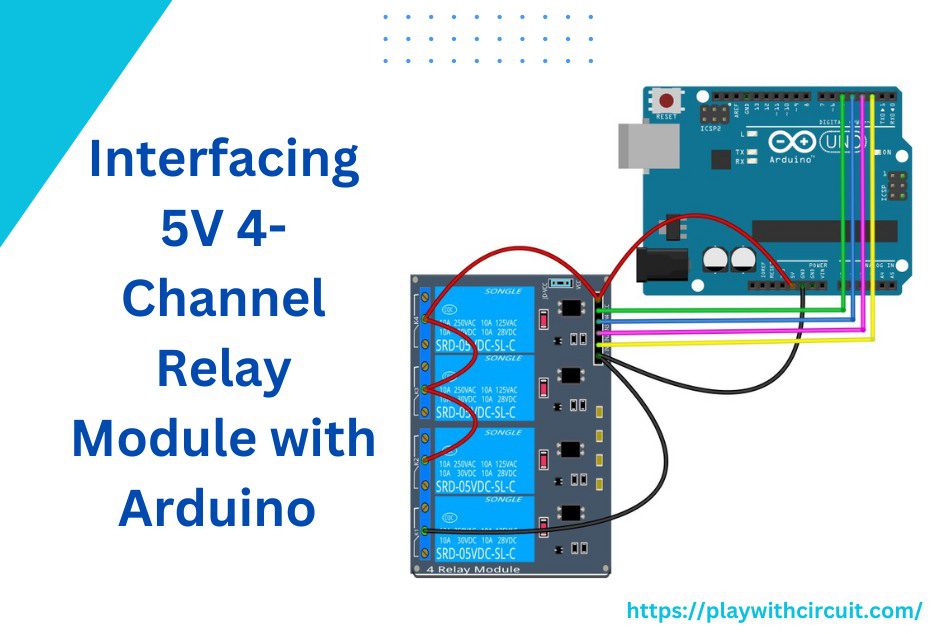
We often need to control electronic devices that require higher power with an Arduino. But Arduino operates on 5 volts, it cannot directly control high-voltage appliances. This is where relays are quite useful. Connecting a relay with Arduino enables us to control high voltage (120-240V) devices like bulbs, heaters, fans, motors and other home appliances.
Interfacing a 5V relay module with an Arduino Uno is a simple and efficient way to control AC/DC appliances. 5V HL-52S relay module is one of the most popular modules that can be connected with Arduino. In this tutorial, we will learn how to control a motor and RGB LED with a HL-52S relay module using Arduino Uno.
How Relays Work?
The relay is an electrically operated switch that consists of an electromagnet, mechanically movable contact, switching points and spring. It can be switched on with a relatively small electric current that can turn ON or OFF another circuit.
Relay works on the principle of electromagnetic induction. Here is an animation that illustrates how a relay can use one circuit to switch on a second circuit:
Initially both the circuits are open, so no current flows through them. When they are turned on, a small current flows through the first circuit, activating the electromagnet which induces a magnetic field around it. The activated electromagnet pulls the metal bar in the second circuit toward it, closing the switch and allowing current to flow through the second circuit. This turns on Green LED in the second circuit.
When the current stops flowing in the first circuit, the contact get back to the original position which reopens the second circuit.
In the above circuit, we’ve used an LED but you can also control a high voltage ac/dc device through relay.
Relay Module vs. Relay
It is important to note the relay is different from the relay module. A relay is a single device that has an electromagnet and a switch, while relay module is a board that has one or multiple relays on it and several other components to provide isolation and protection.
Because of its modular construction, the relay module can have many different configurations. It can be a single-channel relay module or it can be a multi-channel device with multiple relays.
5V Four-Channel Relay Module Pinout
The four-channel relay module contains four 5V relays (each capable of switching a separate electrical circuit or devices) and the associated switching and isolating components. The pinout of a four-channel relay module typically consists of multiple pins, each serving a specific purpose. Let’s take a look:
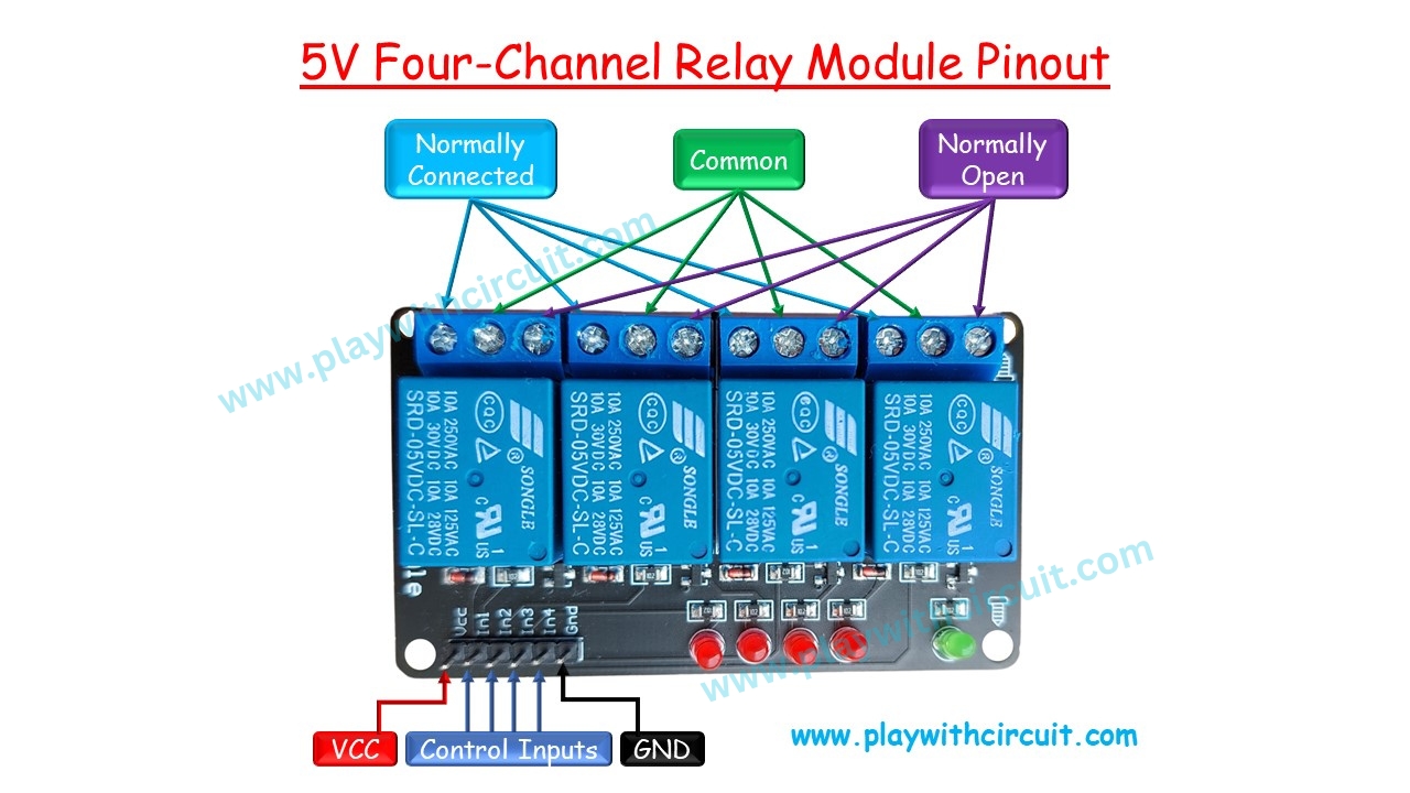
Power and Control Pins
Vcc This pin provides power to the relay module. Connect it to the 5V pin on the Arduino.
GND This pin provides the common ground for the module.
Control Pins (IN1, IN2, IN3, IN4) These pins are the control input for relays. Sending a high or low signal to any of these pins activates or deactivates the relay associated with the pin.
Relay Output Connections
NO-Normally open This pin represents the normally open contact of the relay. Initially, it is not connected to the common (COM) pin, but when the relay is powered on, it gets connected to the common pin.
NC-Normally Connected or Close This pin signifies the normally closed contact of the relay. Initially, it is connected to the common (COM) pin when the relay is inactive, but gets disconnected from the common when the relay is activated.
COM-Common This pin serves as the common contact for the relay. Initially, it is connected to a normally closed (NC) pin, but when the relay is activated, it gets connected to the Normally Open (NO) pin.
5V Four-Channel Relay Module Hardware Overview
A 5V four-channel relay module consists of various hardware components that work together to enable its functionality. Here’s an overview of the hardware parts found in this module:
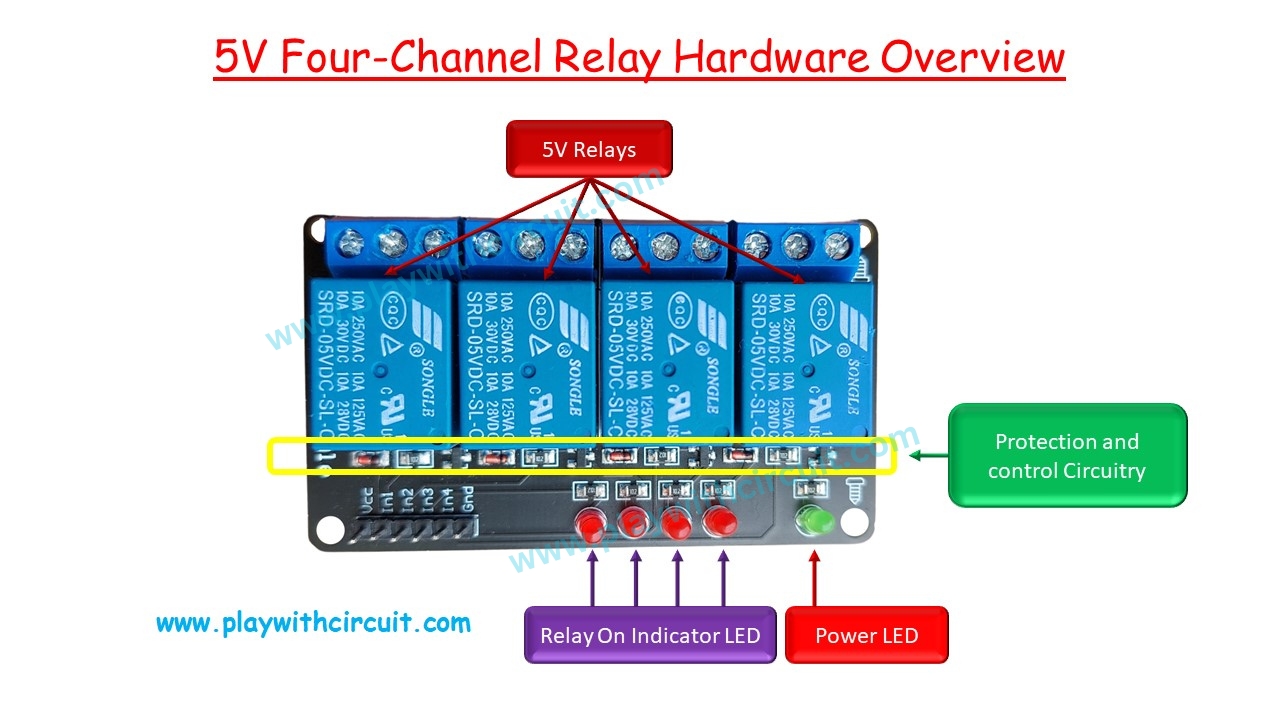
Protection and control circuitry Protection and Control Circuitry consists of active and passive components like transistors, diodes and resistor.
- Resistor: to control the current going into base of transistors.
- Transistor: Each control pin is connected to a transistor, which acts as a switch to control the relay’s coil.
- Diodes: Diodes are used to protect the circuit from voltage spikes and back EMF (Electromotive Force) generated by the relay coils when they are switched off. These diodes, known as flyback diodes, prevent damage to the other components and ensure smooth operation.
5V Relays There are four relays which can be controlled by 5 V Dc which in turn can control maximum 220V AC appliances at 10 Amps current as well as 30V DC appliances at 10 Amps currents.
Power LED The illumination of the power LED indicates that the module’s internal power supply is active and functioning properly. It serves as a visual indicator that the module is ready to operate.
Indicator LEDs There are usually LED indicators associated with each relay channel. These LEDs provide a visual indication of whether the relay is currently active (ON) or inactive (OFF).
Internal Circuit Diagram of 5V Four-Channel Relay Module
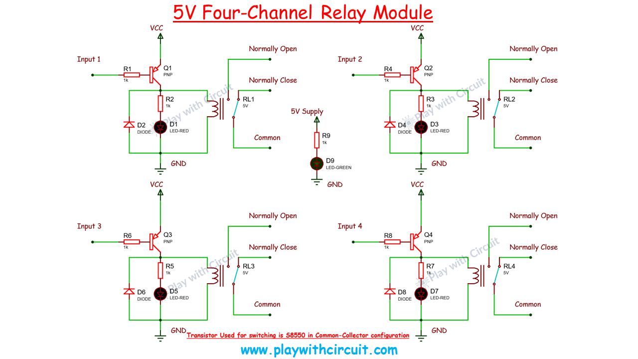
The input of relay board is connected to base of the PNP transistor. When this pin is HIGH the relay is de-energised. When this pin is LOW then 5V supply is shorted with the Relay supply, hence it is activated. In this circuit this PNP transistor acts as NOT GATE.
The flyback diode IN 4148 connected in parallel with coil but in reverse biased, used for protection of circuit from back EMP which is produced by relay when it is turned OFF.
When the relay activates the COM pin is connected to the NO pin. When it deactivates the COM pin is connected to NC pin.
Four-Channel Relay Module Specifications
- Supply voltage – 3.75V to 6V
- Trigger current at input pins– 5mA
- Current through coil when the relay is active – ~70mA (single), ~300mA (all four)
- Relay maximum current at output– 10A
- Relay maximum contact voltage at output– 250VAC, 30VDC
Interfacing a Four-Channel Relay Module with Push Buttons
Now let us learn how to interface 4-Channel Relay module with push button.
In the wiring diagram below, we can see a relay board on which 4 relays are mounted along with other active and passive components.
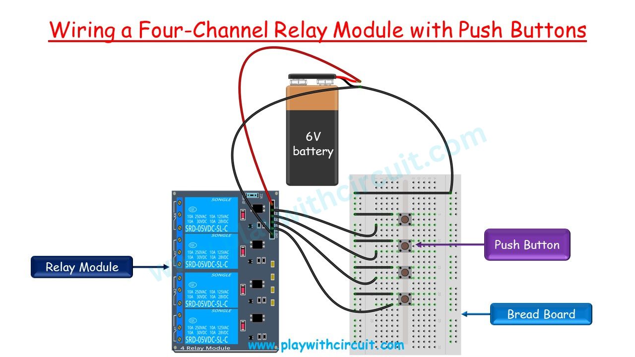
There are four Red status LED which glows when respective relay activates. Also there is one Green coloured power LED which glows when power and ground is connected to board.
A 6V battery is used to give power to relay board. Four input pins IN1, IN2, IN3,In4 are connected to push button which are connected to ground pin of the 6V battery. The circuit of relay board is such that when ground is provided at a particular input that is when push button is pressed then corresponding relay activates and its status LED starts glowing.
NO pin which is previously open is connected to common pin as long as button is pressed, that is as long as input pin is connected to ground.
Output
Components Used
Interfacing Four-Channel Relay Module with Arduino
Interfacing a 4-channel relay with an Arduino Uno is a simple and efficient way to control AC/DC appliances.
We can control AC equipment which can be connected to output of relay using Arduino board which runs on 5V DC.
In this tutorial we will be controlling only DC components using the Relay.
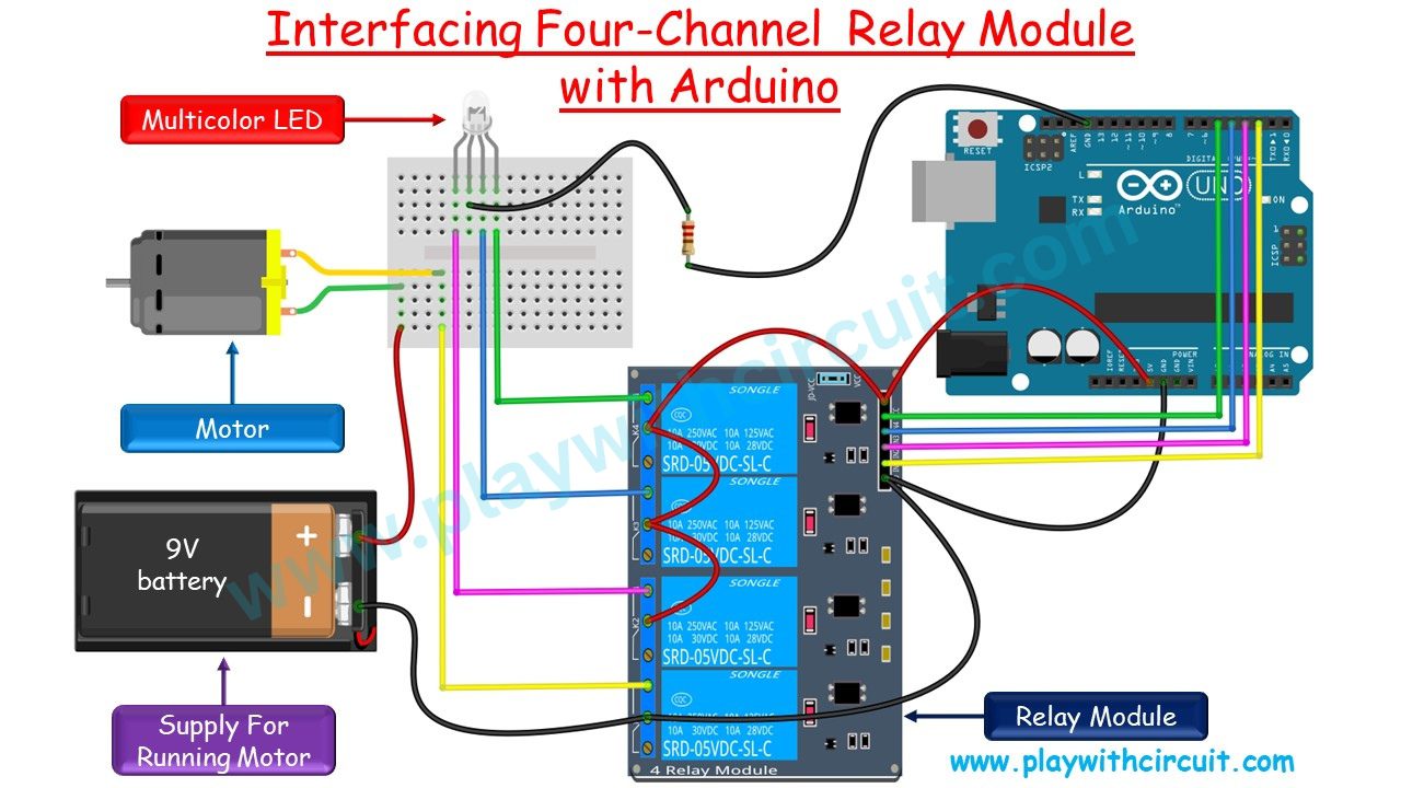
Here, we will be controlling one motor and 3 pins of one multi-coloured LED. First motor will be turned ON then one by one RED, BLUE, GREEN all the anode of LED gets connected to supply and LED will glow in different colours. In the end motor stops and LED will be turned OFF.
![]()
Warning
Do not touch any wires that are connected to mains voltage. Also make sure you have tightened all screws of the relay module.
Components Required
| Component Name | Quantity | Remarks | Where to Buy |
|---|---|---|---|
| Arduino UNO R3 | 1 | Revision R3 | Banggood |
| 9V Battery | 1 | To supply power to Motor | Amazon |
| Bread board | 1 | Half Size | Banggood |
| Multicolour LED | 1 | Common cathode | Amazon | Banggood |
| DC Motor | 1 | 9V DC Motor to run fan | Amazon |
| Jumper Wires | 10 | For Breadboard Connections | Banggood |
| 12V Supply Adapter | 1 | For providing power to Arduino | Amazon |
The connections between Arduino Uno and relay board are as follows:
| Relay Module | Arduino side |
|---|---|
| Vcc | 5V Supply |
| GND | Ground Pin |
| IN1(Motor) | Pin 2 |
| IN2(RED) | Pin 3 |
| IN3(BLUE) | Pin 4 |
| IN4(GREEN) | Pin 5 |
Code for Interfacing Four-Channel Relay Module with Arduino
#define RELAY_ON  0
#define RELAY_OFF 1

#define MOTOR_PIN 2
#define RED_PIN   3
#define BLUE_PIN  4
#define GREEN_PIN 5

void setup() {
  // set the all relay pins as output
  pinMode(MOTOR_PIN, OUTPUT);
  pinMode(RED_PIN, OUTPUT);
  pinMode(BLUE_PIN, OUTPUT);
  pinMode(GREEN_PIN, OUTPUT);
  digitalWrite(MOTOR_PIN, RELAY_OFF);
  digitalWrite(RED_PIN, RELAY_OFF);
  digitalWrite(BLUE_PIN, RELAY_OFF);
  digitalWrite(GREEN_PIN, RELAY_OFF);
}

void loop() {
 // Turn MOTOR_PIN ON
  digitalWrite(MOTOR_PIN, RELAY_ON);
  delay(1000);  // Delay of 1 sec
  // Turn RED_PIN ON
  digitalWrite(RED_PIN, RELAY_ON);
  delay(1000);  // Delay of 1 sec
  // Turn BLUE_PIN ON
  digitalWrite(RED_PIN, RELAY_OFF);
  digitalWrite(BLUE_PIN, RELAY_ON);
  delay(1000);  // Delay of 1 sec
  // Turn GREEN_PIN ON
  digitalWrite(BLUE_PIN, RELAY_OFF);
  digitalWrite(GREEN_PIN, RELAY_ON);
  delay(1000);  // Delay of 1 sec
  delay(1000);  // Delay of 1 sec
  // Turn Off All Relays
  digitalWrite(MOTOR_PIN, RELAY_OFF);
  digitalWrite(RED_PIN, RELAY_OFF);
  digitalWrite(BLUE_PIN, RELAY_OFF);
  digitalWrite(GREEN_PIN, RELAY_OFF);
  delay(1000);  // Delay of 1 sec
  delay(1000);  // Delay of 1 sec
}
The Output of Code
Explanation of Code
In this code we will not be using any external library function hence no include will be required. We will be using only predefined Library Functions.
Initially MACROS are created for Relay state and Arduino pins which control four inputs of relay module using below code.
#define RELAY_ON  0
#define RELAY_OFF 1

#define MOTOR_PIN 2
#define RED_PIN   3
#define BLUE_PIN  4
#define GREEN_PIN 5
Now in the setup() function we set all the control signals as output pins and turn off all the relays, using pinMode() and digitalWrite() functions using below code:
void setup() {
  // set the all relay pins as output
  pinMode(MOTOR_PIN, OUTPUT);
  pinMode(RED_PIN, OUTPUT);
  pinMode(BLUE_PIN, OUTPUT);
  pinMode(GREEN_PIN, OUTPUT);
  digitalWrite(MOTOR_PIN, RELAY_OFF);
  digitalWrite(RED_PIN, RELAY_OFF);
  digitalWrite(BLUE_PIN, RELAY_OFF);
  digitalWrite(GREEN_PIN, RELAY_OFF);
}
Now in the loop() function we will cyclically toggle all the inputs of relay board, which in turn controls the output of relay. delay() function is used to provide intermediate delay in milliseconds.
void loop() {
  // Turn MOTOR_PIN ON
  digitalWrite(MOTOR_PIN, RELAY_ON);
  delay(1000);  // Delay of 1 sec
  // Turn RED_PIN ON
  digitalWrite(RED_PIN, RELAY_ON);
  delay(1000);  // Delay of 1 sec
  // Turn BLUE_PIN ON
  digitalWrite(RED_PIN, RELAY_OFF);
  digitalWrite(BLUE_PIN, RELAY_ON);
  delay(1000);  // Delay of 1 sec
  // Turn GREEN_PIN ON
  digitalWrite(BLUE_PIN, RELAY_OFF);
  digitalWrite(GREEN_PIN, RELAY_ON);
  delay(1000);  // Delay of 1 sec
  delay(1000);  // Delay of 1 sec
  // Turn Off All Relays
  digitalWrite(MOTOR_PIN, RELAY_OFF);
  digitalWrite(RED_PIN, RELAY_OFF);
  digitalWrite(BLUE_PIN, RELAY_OFF);
  digitalWrite(GREEN_PIN, RELAY_OFF);
  delay(1000);  // Delay of 1 sec
  delay(1000);  // Delay of 1 sec
}
FAQ’S
What is the function of 4 channel 5V relay module?
A 4-channel 5V relay module acts as an interface between Arduino and higher-voltage electrical devices or circuits. This module has four independent relays, each capable of acting as a switch to control the power supply to different channels. The primary function of these relays is to provide electrical isolation between the low-voltage control circuit (typically powered by 5V) and the high-voltage load circuit. This isolation protects the sensitive microcontroller components from potential damage caused by voltage fluctuations or spikes in the load.
Can I connect the relay directly to Arduino?
Yes, you can connect a relay directly to an Arduino. Typically, a relay module has an integrated circuit to protect the Arduino from potential back electromotive force generated by the relay coil.
What type of relay is used in Arduino?
In Arduino projects, generally an electromagnetic relay module is used. These modules typically include an electromechanical relay with a control circuit, allowing it to be easily controlled by the low-voltage signals generated by Arduino digital pins.
What are the applications of 4 channel relay?
A 4-channel relay can be used for home automation (lighting, appliances), security systems (access control, surveillance), industrial automation (machinery, motors), smart agriculture (irrigation, greenhouse automation), audio-visual systems, robotics, DIY electronics projects, energy management, remote control systems (vehicles, drones), etc.
