
Pulse width modulation is a very useful technique for controlling things with Arduino. You can control LED brightness, the speed of the DC Motor, the direction of the Servo Motor, etc. using PWM.
In this tutorial, we will explore Pulse Width Modulation (PWM), and how to use it to control the brightness of an LED.
What is Pulse Width Modulation (PWM)?
Many Arduino boards have digital output pins that can only provide two states: HIGH (5V) or LOW (0V). However, many devices require analog signals with varying voltage levels to control their behaviour, such as dimming an LED.
As Arduino UNO doesn’t have a Digital to Analog converter to produce an analog signal hence PWM is required. By using PWM, we can simulate any voltage between 0V to 5V by changing the width of the pulses.
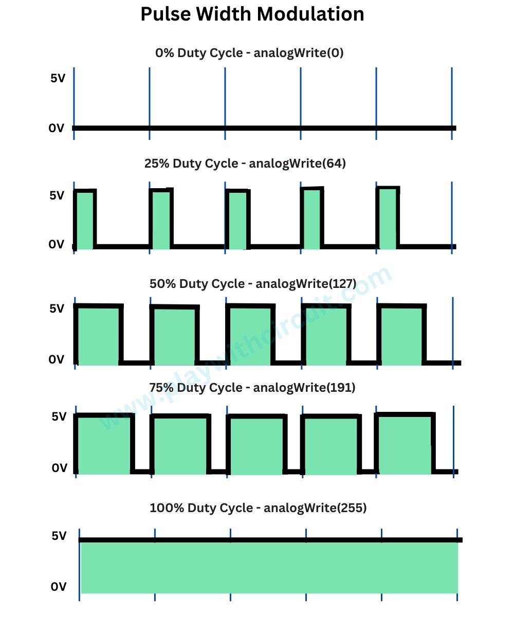
This technique switches a square wave between ON and OFF states. This on-off pattern can simulate voltages between the board’s Vcc (e.g. 5V on UNO) and OFF (0V) by changing the portion of the time the signal remains ON versus the time that the signal remains OFF. The duration of “ON time” is called the pulse width. So, to get varying analog values, we change or modulate that pulse width.
What is the Duty Cycle of PWM Signal?
The duty cycle of a PWM (Pulse Width Modulation) signal refers to the percentage of time the signal is ON (high) divided by the total time of the signal’s period. It represents how much of the time the signal remains high in the total time period.
Duty Cycle = (ON Time / Time period) * 100
e.g., A pulse with a period of 20ms will remain ON (HIGH) for 5ms. Therefore, duty cycle will be
D = 2ms / 10ms = 25%
If a digital signal spends half of the time ON (High state) and the other half OFF (Low state), we call it a square wave with a 50% duty cycle. If the duty cycle is more than 50%, it means the signal is spending more time ON than OFF. And if it’s less than 50%, it’s spending more time OFF than ON. Here is an image that illustrates these three scenarios:
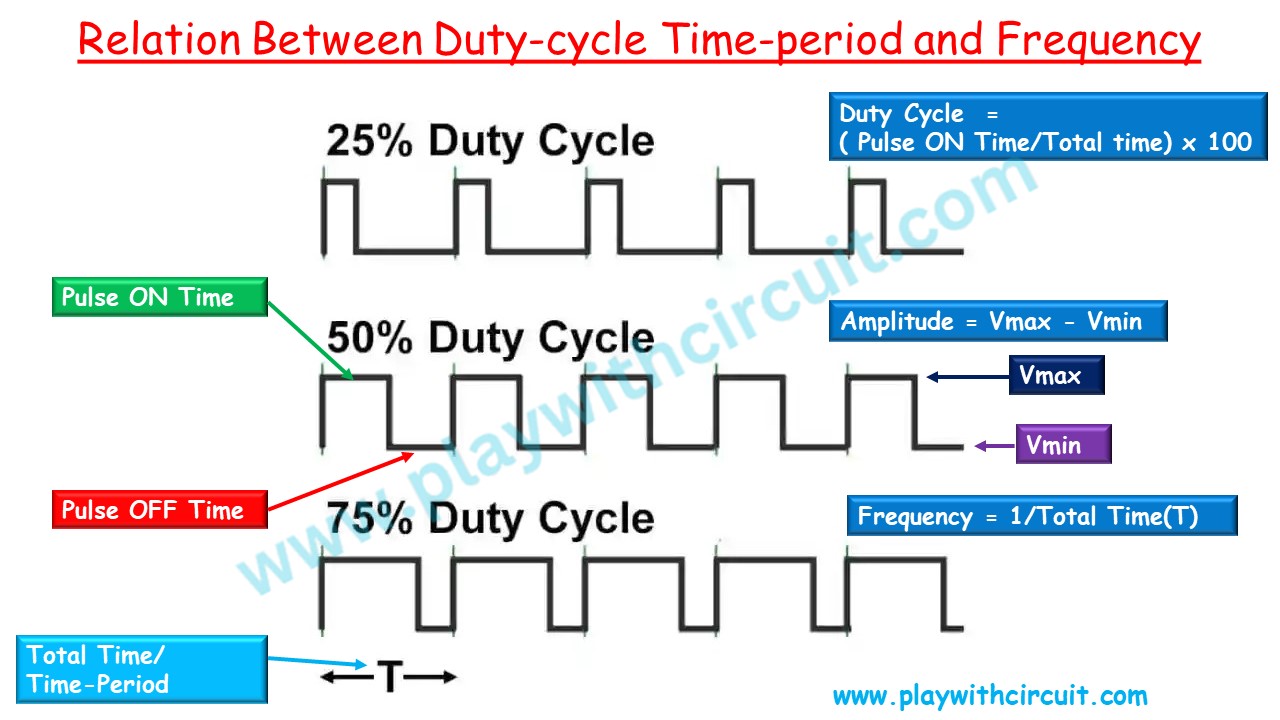
100% duty cycle means setting the voltage to 5 volts (high). 0% duty cycle represents the lowest voltage level (e.g., 0 volts).
Amplitude of a PWM
The amplitude of a PWM signal refers to the difference between its maximum and minimum voltage levels. In simpler terms, it represents the range of voltage values that the PWM signal can produce.
Amplitude = Vmax – Vmin
For example, if a PWM signal can vary between 0 volts (minimum) and 5 volts (maximum), then its amplitude would be 5 volts.
Duty Cycle to Analog Conversion
Analog Output Voltage = ( Duty cycle / 100 ) * Amplitude of the pulse
What is the Frequency of PWM Signal?
The frequency of a PWM signal refers to the number of times the signal repeats its cycle within one second. It is typically measured in Hertz (Hz), which represents cycles per second.
In simpler terms, the frequency indicates how fast the PWM signal switches between its ON and OFF states. A higher frequency means the signal switches more rapidly, while a lower frequency means it switches more slowly.
For example, if a PWM signal has a frequency of 100 Hz, it completes 100 cycles in one second.
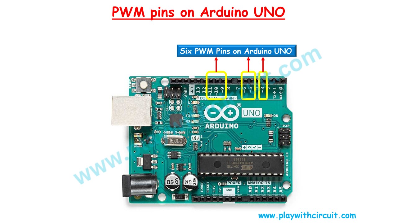
Arduino Pins Capable of PWM
In Arduino boards, several pins are capable of generating PWM signals. These pins are marked with a tilde (~) symbol on the board, such as digital pins 3, 5, 6, 9, 10, and 11 in Arduino Uno. This feature allows for easy implementation of PWM-based applications without the need for additional hardware.
| Board | Pins | Freqeuncy |
|---|---|---|
| UNO (R3 and earlier), Nano, Mini | 3, 5, 6, 9, 10, 11 | 490 Hz (pins 5 and 6: 980 Hz) |
| UNO R4 (Minima, WiFi) * | 3, 5, 6, 9, 10, 11 | 490 Hz |
| Mega | 2 - 13, 44 - 46 | 490 Hz (pins 4 and 13: 980 Hz) |
| GIGA R1 ** | 2 - 13 | 500 Hz |
| Leonardo, Micro | 3, 5, 6, 9, 10, 11, 13 | 490 Hz (pins 3 and 11: 980 Hz) |
| UNO WiFi Rev2, Nano Every | 3, 5, 6, 9, 10 | 976 Hz |
| MKR boards * | 0 - 8, 10, A3, A4 | 732 Hz |
| MKR1000 WiFi ** | 0 - 8, 10, 11, A3, A4 | 732 Hz |
| Zero ** | 3 - 13, A0, A1 | 732 Hz |
| Due *** | 2-13 | 1000 Hz |
Some Useful Arduino Functions Related to Analog Pins
analogWrite() Function
The Arduino analogWrite() function is used to generate a Pulse Width Modulation signal on a digital pin of the Arduino board.
Syntax: analogWrite(pin, value);
Parameters: It takes two parameters:
- Pin: It specifies the digital pin number where the PWM signal will be generated.
- Value: This parameter specifies the duty cycle of the PWM signal, ranging from 0 to 255.
The PWM frequency produced by analogWrite() is fixed and depends on the specific Arduino board. For Arduino Uno and similar boards, the PWM frequency is approximately 490 Hz for pins 3, 9, 10, and 11 and 980 Hz for pins 5 and 6.
analogRead() Function
This function is used to read the value of analog signal given to pin A0 to A5. Arduino UNO has 10-bit ADC hence this function returns 0 – 1023 based on the signal applied 0 to 5V.
Syntax: analogRead(pin);
Parameters:
- Pin: name of the analog input pin to read. It can be A0, A1, A2, A3, A4, A5.
- Returns: This function returns the analog reading on the Analog input pin min 0, max 1023.
map() function
This function is used to convert one range of values into another.
Syntax: map(inputValue, currentLow, currentHigh, targetLow, targetHigh)
Parameters:
- inputValue: the input value which needs to be mapped.
- currentLow: min input value.
- currentHigh: max input value.
- targetLow: min output value for min input.
- targetHigh: max output value for max input.
The data type of all input parameters is signed long. It can handle negative values as well.
Returns: It returns the mapped value against inputValue. Data type: long.
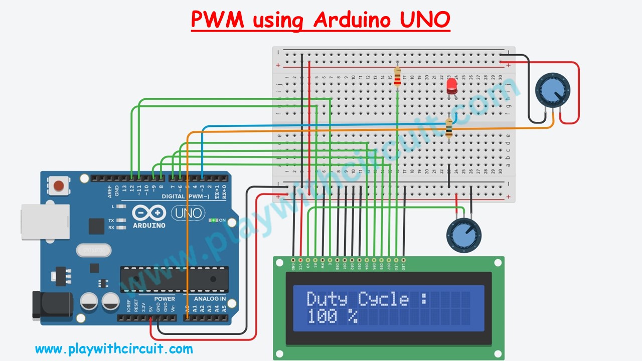
Controlling the Brightness of an LED using the PWM on Arduino UNO
In this section, we will write a program for Arduino to control the brightness of LED using the PWM pin. The duty cycle can be varied using a POT connected at analog input pin A0.
The analog value is read from the analog input A0 and this value will always be in the range of 0 to 1023. This value is mapped to the range of PWM value in the range of 0 to 255. This PWM value will be provided to the PWM pin which is connected to the LED. Later this PWM value is converted to duty cycle and is displayed on the 16×2 LCD.
💡Must Read
Interfacing 16×2 LCD with Arduino
In this article, you will learn about how to interface a 16×2 LCD with an Arduino UNO and how to display custom characters on the LCD.
Hardware and Software Requirements
Hardware Requirements
| Sr. No. | Component Name | Quantity | Remarks | Where to Buy |
|---|---|---|---|---|
| 1 | Arduino UNO R3 | 1 | Revision R3 | Amazon |
| 2 | LED | 1 | 5mm diameter | Amazon |
| 3 | Resistance | 1 | 220 ohm, ¼ watt for connection with LCD | Amazon |
| 4 | Resistance | 1 | 100 ohm, ¼ watt for connection with LED | Amazon |
| 5 | POT | 2 | 10k-ohm, one for connection with LCD and one for controlling the duty cycle | Amazon |
| 6 | Breadboard | 1 | Big size | Amazon |
| 7 | Connection wires | 25 | For breadboard and Arduino connections | Amazon |
Connections
The connections between Arduino Uno and LCD is as follows:
| LCD side Pin | Arduino side/ Breadboard Connection |
|---|---|
| VSS/GND (Pin 1) | Connected to Ground |
| VDD/VCC (Pin 2) | Connected to 5V |
| VEE/Vo (Pin 3) | Connected to Variable pin of 10k POT to Control Contrast of LCD |
| RS (Pin 4) | 12 |
| R/W (Pin 5) | Connected to Ground |
| Enable (Pin6) | 11 |
| D0 (Pin 7) | Pulled to Ground, No connection with Arduino |
| D1 (Pin 8) | Pulled to Ground, No connection with Arduino |
| D2 (Pin 9) | Pulled to Ground, No connection with Arduino |
| D3 (Pin 10) | Pulled to Ground, No connection with Arduino |
| D4 (Pin 11) | 6 |
| D5 (Pin 12) | 7 |
| D6 (Pin 13) | 8 |
| D7 (Pin 14) | 9 |
| LED(+) (Pin 15) | Connected to Vcc via 220 ohm resistor |
| LED(-) (Pin 16) | Connected to Ground |
Software Requirement
Arduino IDE, Version 2.1.1 or above installed on your PC.
Code
/*
Controlling the Brightness of an LED using the PWM on Arduino UNO
by www.PlaywithCircuit.com
*/
#include <LiquidCrystal.h>

LiquidCrystal lcd(12, 11, 6, 7, 8, 9);

#define DUTYCYCLE_PIN A0
#define LED_PIN 3

void setup() {
  // Set up the LED pin as an output
  pinMode(LED_PIN, OUTPUT);
  // set up the LCD's number of columns and rows
  lcd.begin(16, 2);
  // set the cursor to (column = 0,row = 0)
  lcd.setCursor(0, 0);
  lcd.print("Duty Cycle :");
}

void loop() {
  // Read the value from the potentiometer
  int potValue = analogRead(DUTYCYCLE_PIN);

  // Map the potentiometer value to the range of PWM (0-255)
  int PWM_Value = map(potValue, 0, 1023, 0, 255);

  // Update the LED brightness (duty cycle)
  analogWrite(LED_PIN, PWM_Value);

  // Map the PWM_Value value to the range of DutyCycle (0-100)
  int dutyCycle = map(PWM_Value, 0, 255, 0, 100);

  // Print the Duty Cyle on the LCD
  lcd.setCursor(0, 1);
  lcd.print(dutyCycle);
  lcd.print(" %   ");

  // Delay to stabilize readings
  delay(100);
}
Output:
Code Explanation
In this code we are using LCD hence the Library of the LCD is included and input and output pins are defined using below lines:
#include <LiquidCrystal.h>

LiquidCrystal lcd(12, 11, 6, 7, 8, 9);

#define DUTYCYCLE_PIN A0
#define LED_PIN 3
In the setup() function the LED pin is set as output pin and LCD is initialized using below lines of code.
void setup() {
  // Set up the LED pin as an output
  pinMode(LED_PIN, OUTPUT);
  // set up the LCD's number of columns and rows:
  lcd.begin(16, 2);
  // set the cursor to (column = 0,row = 0)
  lcd.setCursor(0, 0);
  lcd.print("Duty Cycle :");
}
In the loop() function first the analog value is read from the analog input pin A0.
  // Read the value from the potentiometer
  int potValue = analogRead(DUTYCYCLE_PIN);
Then this value is mapped to PWM value using the map function and this PWM value is given to the PWM pin which is connected to the LED.
  // Map the potentiometer value to the range of PWM (0-255)
  int PWM_Value = map(potValue, 0, 1023, 0, 255);

  // Update the LED brightness (duty cycle)
  analogWrite(LED_PIN, PWM_Value);
In the later part of loop() function, the PWM value is mapped to the duty cycle which is displayed on the LCD.
  // Map the PWM_Value value to the range of DutyCycle (0-100)
  int dutyCycle = map(PWM_Value, 0, 255, 0, 100);

  // Print the Duty Cyle on the LCD
  lcd.setCursor(0, 1);
  lcd.print(dutyCycle);
  lcd.print(" %   ")


