
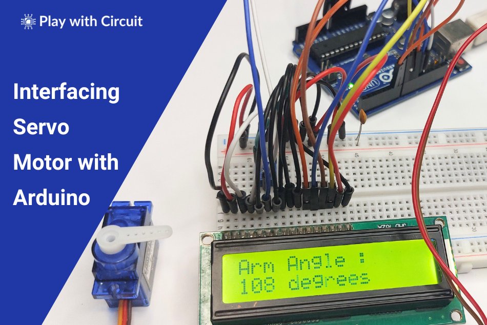
Servo motors are widely used in various Arduino projects due to their precise motion control and ease of integration. Their ability to accurately rotate to specific angles and maintain positions make them ideal for robotics and automation applications e.g., controlling the movement of robotic arms, conveyor belts, or grippers.
In this tutorial, we will learn how servo motors work and how to interface them with Arduino UNO and control their movement using the inbuilt Servo library of Arduino IDE as well as without using the library. We will also learn how to make a Servo Tester.
What is a Servo Motor?
A servo motor is a rotary actuator that can rotate or move to a specific position, speed, allowing for precise control of angular position, acceleration, and velocity. It consists of a small dc motor, gear train, a sensor for position feedback, control circuitry and output shaft.
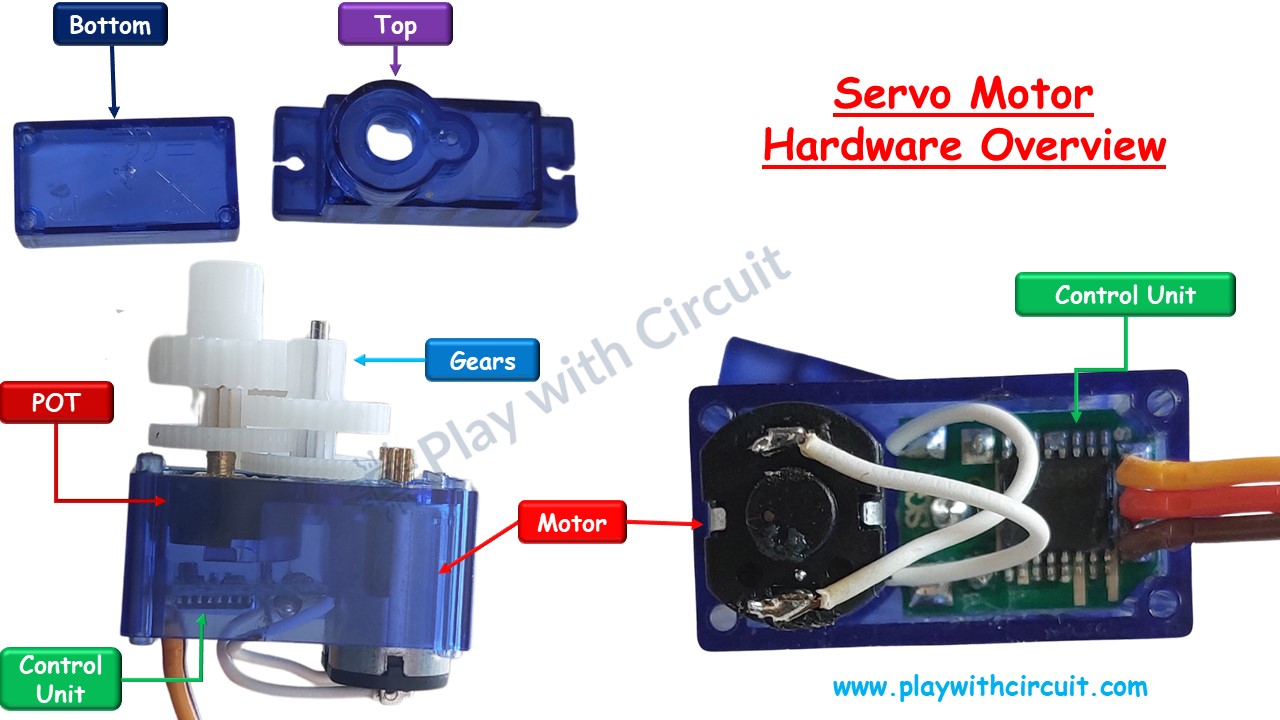
The feedback sensor such as a potentiometer or an encoder provides feedback on the motor’s current position to the control system which compares the current position to the desired position. The control system adjusts the motor’s position accordingly to ensure that the motor accurately reaches the desired position. This mechanism is called a servomechanism, which is a closed-loop control system that uses feedback to control the position and speed of the motor.
Servo Motor Working
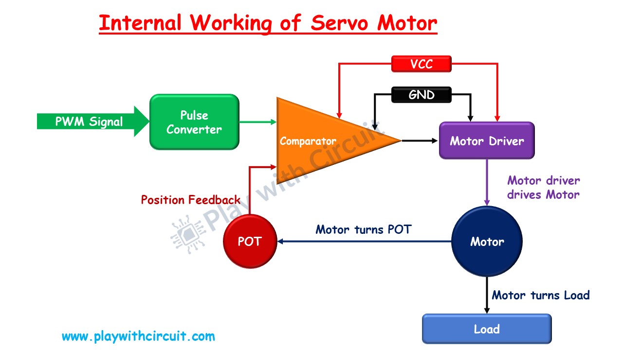
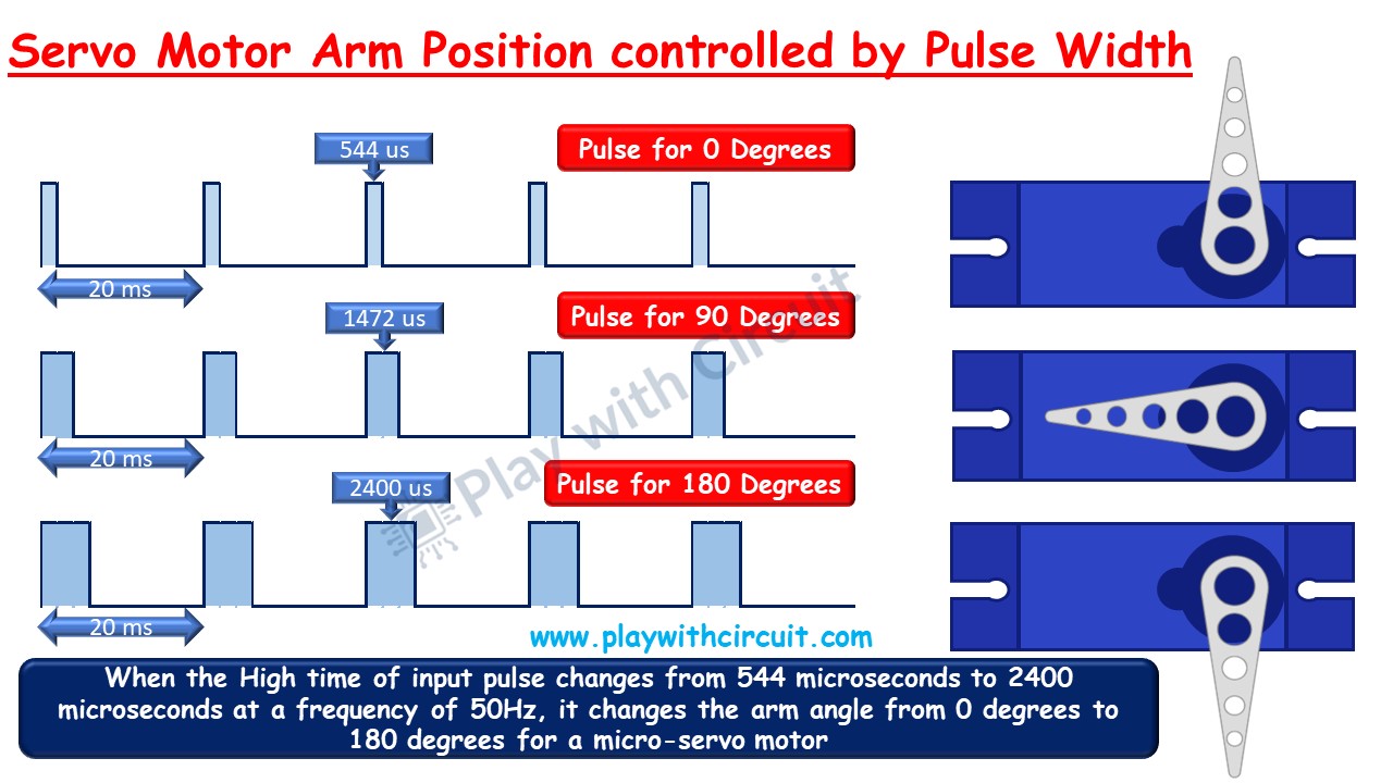
You can control the angle of rotation of servo motors by using PWM (Pulse Width Modulation) signals. These signals are generated by a microcontroller, such as an Arduino, and are sent to the servo motor’s control input.
The PWM signal is a square wave with a variable duty cycle. When you send a PWM signal to a servo motor, its control circuit measures the duration when the signal is high, which determines the position of the servo motor. For example,
- A pulse duration of 544 µs will rotate the servo to 0 degrees.
- A pulse duration of 1472 µs will rotate the servo to 90 degrees (middle position).
- A pulse duration of 2400 µs will rotate the servo to 180 degrees.
This mechanism allows the servo motor to accurately match the input PWM signal, ensuring precise angular positioning.
What is SG-90 Servo Motor?
The SG-90 is a popular small-sized servo motor used in robotics, DIY projects and electronics applications. It typically has a rotation range of around 180 degrees and offers maximum torque of 1.8 kg-cm making it ideal for tasks such as controlling the movement of small robotic arms, steering mechanisms in remote-controlled vehicles, or adjusting the position of sensors or cameras.
Features of Tower Pro SG-90 Servo Motor
- Weight: 9 g
- Dimension: 22.2 x 11.8 x 31 mm approx.
- Stall torque: 1.8 kgf·cm
- Operating speed: 0.1 s/60 degree
- Operating voltage: 4.8 V (~5V)
- Dead bandwidth: 10 µs
- Temperature range: 0 ºC – 55 ºC
Servo Motor Pinout
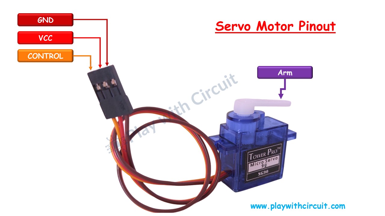
VCC This pin is connected to the positive terminal of the power supply and provides the voltage required for the operation of the servo motor.
GND This pin is connected to the negative terminal of the power supply and serves as the ground reference for the servo motor.
Control This pin is used to control the position of the servo motor. It receives pulse-width modulation (PWM) signals from a microcontroller.
Interfacing Arduino with Servo Motors
In this section we will be interfacing an Arduino UNO with the SG-90 micro servo motor.
Hardware and Software Requirements
Hardware
| Component Name | Quantity | Remarks |
|---|---|---|
| Arduino UNO R3 | 1 | Revision R3 |
| Micro Servo Motor | 1 | SG 90 |
| Connection wires | 3 | For Motor and Arduino connections |
| 12V Supply Adapter | 1 | For providing power to Arduino |
Software
- Arduino IDE, version 2.1.1 or above installed on your PC
- Servo Library by Arduino.
Commonly Used Functions of Servo Library
Sure, let’s look at functions provided by the Servo library in Arduino:
Servo Class
Create an instance of the Servo class, representing a servo motor.
Syntax
Servo servo;Parameter
servo: An object of type Servo
attach()
This function connects or attaches the servo motor to a specific pin on the Arduino board. It establishes a communication link between the Arduino and the servo motor.
Syntax
servo.attach(pin)
servo.attach(pin, min, max)
Parameters
- servo: An object of type Servo
- pin: The pin on which servo motor’s control (orange) wire is connected.
- min (optional): The pulse width (in microseconds) corresponding to the minimum (0 degree) angle on the servo (defaults to 544)
- max (optional): the pulse width (in microseconds) corresponding to the maximum (180 degree) angle on the servo (defaults to 2400)
write()
This function instructs the servo motor to rotate to a specified angle. The angle parameter is given in degrees and ranges from 0 to 180, representing the full range of motion of most servo motors. When you call this function with a specific angle, the servo motor adjusts its position accordingly.
Syntax
servo.write(angle)Parameters
- servo: An object of type Servo
- angle: The value to write to the servo, from 0 to 180
writeMicroseconds()
This function provides a more precise way to control the position of the servo motor. Instead of specifying the angle directly, you specify the desired position using the pulse width in microseconds. This allows for finer control over the servo motor’s movement.
Syntax
servo.writeMicroseconds(us)Parameters
servo: An object of type Servo
us: the value of the parameter in microseconds (int)
read()
This function reads the current angle of the servo motor and returns it as a value in degrees. It’s useful if you need to know the current position of the servo motor for feedback or control purposes.
Syntax
servo.read()Parameters
servo: An object of type Servo
Returns: The angle of the servo, from 0 to 180 degrees.
attached()
This function checks whether the servo motor is currently attached to a pin on the Arduino board. It returns true if the servo is attached and false if it’s not attached.
Syntax
servo.attached()Parameters
servo: An object of type Servo
Returns: true if the servo is attached to pin; false otherwise.
detach()
This function detaches the servo motor from the pin it’s currently connected to. When you detach a servo motor, it stops responding to commands from the Arduino until you reattach it using the attach() function.
Syntax
servo.detach()Parameter
servo: An object of type Servo
Connection Diagram for Interfacing Arduino with Servo Motors
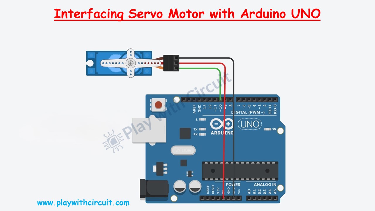
In the above wiring diagram, we can see a micro–servo motor is connected with the Arduino UNO. The power pin of Servo is connected to the Vcc of the Arduino UNO using red wire. The Ground pin is connected to the Gnd pin of Arduino using red. This control pin is connected to pin 10 of the Arduino with its PWM pin.
Arduino Example Code 1
In the below code, we will be controlling the position of Arm of servo from 0 to 180 degrees with Arduino UNO. We will be using the Servo Library by Arduino.
Code:
/*
Interfacing Micro Servo Motor with Arduino without using servo library
by www.playwithcircuit.com
*/
#include <Servo.h>
#define SERVO_PIN   10

Servo myservo;                          // create servo object to control a servo

int pos = 0;                            // variable to store the servo position

void setup() {
  myservo.attach(SERVO_PIN);            // attaches the servo on pin 9 to the servo object
  myservo.write(pos);                   // go to position zero first
  delay(2000);                          // wait for some time
}

void loop() {
  delay(1000);                          // delay of 1 second before start
  for (pos = 0; pos <= 180; pos += 1) { // goes from 0 degrees to 180 degrees in steps of 1 degree
    myservo.write(pos);                 // tell servo to go to position in variable 'pos'
    delay(15);                          // waits 15 ms for the servo to reach the position
  }
  delay(1000);                          // delay of 1 second before changing direction of rotation
  for (pos = 180; pos >= 0; pos -= 1) { // goes from 180 degrees to 0 degrees
    myservo.write(pos);                 // tell servo to go to position in variable 'pos'
    delay(15);                          // waits 15 ms for the servo to reach the position
  }
}
Code Explanation
First, we include the Servo Library and define the pin number SERVO_PIN to which the servo motor is connected.
#include <Servo.h>
#define SERVO_PIN 10
An instance of the Servo class named myservo is created. The variable pos is initialized to 0, which will store the current position of the servo motor.
Servo myservo;
int pos = 0;
In the setup() function, the servo motor is attached to the defined pin SERVO_PIN using attach(). The servo motor is positioned at 0 degrees using write(). A delay of 2 seconds is added to allow time for the servo to reach its initial position.
void setup() {
  myservo.attach(SERVO_PIN);            // attaches the servo on pin 9 to the servo object
  myservo.write(pos);                   // go to position zero first
  delay(2000);                          // wait for some time
}
In the loop() function, there’s a 1-second delay before starting the movement. The first for loop increases the servo position from 0 to 180 degrees in steps of 1 degree. After reaching 180 degrees, there’s another 1-second delay. The second for loop decreases the servo position from 180 to 0 degrees. The delay(15) inside each loop ensures a small delay between each position change, resulting in smooth motion.
void loop() {
  delay(1000);                          // delay of 1 second before start
  for (pos = 0; pos <= 180; pos += 1) { // goes from 0 degrees to 180 degrees in steps of 1 degree
    myservo.write(pos);                 // tell servo to go to position in variable 'pos'
    delay(15);                          // waits 15ms for the servo to reach the position
  }
  delay(1000);                          // delay of 1 second before changing direction of rotation
  for (pos = 180; pos >= 0; pos -= 1) { // goes from 180 degrees to 0 degrees
    myservo.write(pos);                 // tell servo to go to position in variable 'pos'
    delay(15);                          // waits 15 ms for the servo to reach the position
  }
}
Arduino Example Code 2
In the below code, we will be controlling the position of Arm of servo from 0 to 180 degrees with Arduino UNO. We will write a new function to control the servo motor.
Code:
/*
Interfacing Micro Servo Motor with Arduino without using Library
by www.playwithcircuit.com
*/

#define PULSE_TIME 20000                // in microseconds
#define SERVO_PIN 10                  // Pin for communicating with servo motor

int pos = 0;                            // variable to store the servo position
void servo_write(unsigned char angle);
void setup() {
  pinMode(SERVO_PIN,OUTPUT);            // set the mode of Servo pin as output
  for(int i=0; i<30; i++){             // set angle to zero
    servo_write(pos);
    delay(30);
  }
  delay(1000);                          // wait for 1 sec
}

void loop() {
  delay(1000);                          // delay of 1 second before start
  for (pos = 0; pos <= 180; pos += 1) { // goes from 0 degrees to 180 degrees in steps of 1 degree
    servo_write(pos);                   // tell servo to go to position in variable 'pos'
    delay(15);                          // waits 15 ms for the servo to reach the position
  }
  delay(1000);                          // delay of 1 second before changing direction of rotation
  for (pos = 180; pos >= 0; pos -= 1) { // goes from 180 degrees to 0 degrees
    servo_write(pos);                   // tell servo to go to position in variable 'pos'
    delay(15);                          // waits 15 ms for the servo to reach the position
  }
}

void servo_write(unsigned char angle)
{
  unsigned int highPulseTime;
  unsigned int lowPulseTime;
  // high pulse time should vary from 544 microseconds to 2000 microseconds to change angle from 0 to 180 degree
  highPulseTime = map(angle,0,180,544,2400);
  // set low pulse time by subtracting high pulse time from 20000 microseconds or 20 milliseconds as this is the time period of pulse for Servo Motor
  lowPulseTime =  PULSE_TIME - highPulseTime;

  // Now create a 50 Hz pulse
  digitalWrite(SERVO_PIN,HIGH);
  delayMicroseconds(highPulseTime);     // High time
  digitalWrite(SERVO_PIN,LOW);
  delayMicroseconds(lowPulseTime);     // Low time
}
Code Explanation
First, we define two constants. PULSE_TIME represents the total pulse duration in microseconds, and SERVO_PIN specifies the pin connected to the servo motor. An integer variable pos is initialized to store the current position of the servo motor.
#define PULSE_TIME 20000
#define SERVO_PIN 10
int pos = 0;
A function prototype for servo_write() is declared. This function will be used to control the servo motor.
void servo_write(unsigned char angle);In the setup() function, the mode of the servo pin is set as output. The servo_write() function is called 30 times with pos set to 0, allowing the servo to reach its initial position. A delay of 1 second is added to ensure stability before starting the main loop.
void setup() {
  pinMode(SERVO_PIN,OUTPUT);            // set the mode of Servo pin as output
  for(int i = 0; i<30; i++){             // set angle to zero
    servo_write(pos);
    delay(30);
  }
  delay(1000);                          // wait for 1 sec
}
In the loop() function, there’s a 1-second delay before starting the movement. The first for loop gradually increases the servo position from 0 to 180 degrees in steps of 1 degree. After reaching 180 degrees, there’s another 1-second delay. The second for loop gradually decreases the servo position from 180 to 0 degrees.
void loop() {
  delay(1000);                          // delay of 1 second before start
  for (pos = 0; pos <= 180; pos += 1) { // goes from 0 degrees to 180 degrees in steps of 1 degree
    servo_write(pos);                   // tell servo to go to position in variable 'pos'
    delay(15);                          // waits 15 ms for the servo to reach the position
  }
  delay(1000);                          // delay of 1 second before changing direction of rotation
  for (pos = 180; pos >= 0; pos -= 1) { // goes from 180 degrees to 0 degrees
    servo_write(pos);                   // tell servo to go to position in variable 'pos'
    delay(15);                          // waits 15 ms for the servo to reach the position
  }
}
The servo_write() function:
- Calculates the high pulse time based on the desired angle.
- Subtracts the high pulse time from PULSE_TIME to calculate the low pulse time.
- Generates a 50 Hz pulse by setting the servo pin high for the high pulse time, and low for the low pulse time.
void servo_write(unsigned char angle)
{
  unsigned int highPulseTime;
  unsigned int lowPulseTime;
  // high pulse time should vary from 544 microseconds to 2000 microseconds to change angle from 0 to 180 degree
  highPulseTime = map(angle,0,180,544,2400);
  // set low pulse time by subtracting high pulse time from 20000 microseconds or 20 milliseconds as this is the time period of pulse for Servo Motor
  lowPulseTime =  PULSE_TIME - highPulseTime;

  // Now create a 50 Hz pulse
  digitalWrite(SERVO_PIN,HIGH);
  delayMicroseconds(highPulseTime);     // High time
  digitalWrite(SERVO_PIN,LOW);
  delayMicroseconds(lowPulseTime);     // Low time
}
Output:
What is a Servo Tester?
A servo tester is a device used to test and calibrate servo motors. Servo tester typically consist of a small electronic device with knobs or buttons that allow users to manually adjust the position of the servo motor and test its responsiveness. They often include features such as adjustable pulse width modulation (PWM) signals, which are used to control the servo motor’s position, speed, and direction.
You can connect the servo motor to the tester, adjust the settings as needed, and observe how the motor responds. This allows you to test that the servo motor is functioning correctly and to fine-tune its performance for specific applications.
Making a Servo Tester using Arduino UNO
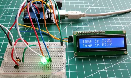
In this section we will be building a Servo Tester to test a servo motor using Arduino. The knob for changing the position/angle of arm is a 10 k-Ohm pot. The middle pin of POT will be connected to the Analog input A0. As soon as the knob rotates, the servo rotates and the angle is displayed on the LCD. If the current angle of the servo arm with respect to the start position (angle 0) is changing as per the angle value displayed on the LCD then servo motor is OK else it is faulty.
Hardware and Software Requirements
Hardware
| Component Name | Quantity | Remarks | Where to Buy |
|---|---|---|---|
| Arduino UNO R3 | 1 | Revision R3 | Amazon.com / Amazon.in / Banggood |
| Micro Servo Motor | 1 | SG 90 | Amazon.com / Amazon.in / Banggood |
| LCD | 1 | 16x2, to display Servo Arm Angle | Amazon.com / Amazon.in / Banggood |
| Resistance | 1 | 220 Ω for using with LCD | Amazon.com / Amazon.in / Banggood |
| POT | 2 | 10kΩ | Amazon.com / Amazon.in / Banggood |
| Breadboard | 1 | Full Size | Amazon.com / Amazon.in / Banggood |
| 12V Supply Adapter | 1 | For providing power to Arduino | Amazon.com / Amazon.in / Banggood |
| Connection wires | 25 | For breadboard connections | Amazon.com / Amazon.in / Banggood |
| USB Cable Type A to B | 1 | for programming Arduino UNO | Amazon.com / Amazon.in |
Software
- Arduino IDE, Version 2.1.1 or above installed on your PC
- Servo Library by Arduino.
- LiquidCrystal Library by Arduino, Version 1.0.7 installed in Arduino IDE
Wiring Diagram
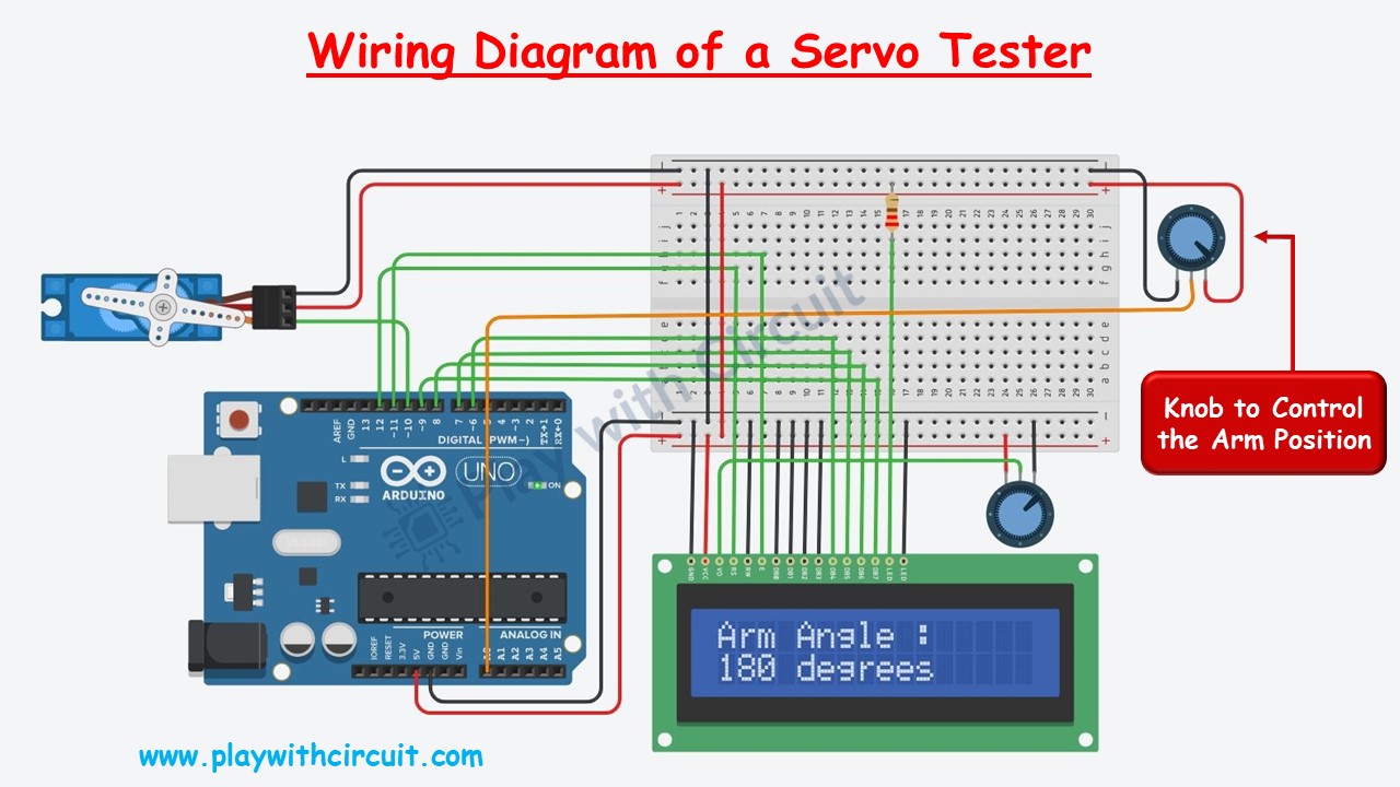
In the above wiring diagram of Servo Tester there is a 10K Ohm pot which is used to control the position of the arm of servo motor using Arduino UNO. The current angle of arm with respect to starting position is displayed on the LCD.
The knob to control the servo is connected at Analog input A0 and the control pin of the servo motor is connected at pin 10 of Arduino UNO. The remaining two pins of Servo as well as knob are connected to VCC and Ground pin of the Arduino.
The connections of Arduino and LCD is given in the following table:
LCD and Arduino Connections
| Sr. No. | LCD Side Pin | Arduino Side Connection |
|---|---|---|
| 1 | VSS/GND (Pin 1) | Connected to Ground |
| 2 | VDD/VCC (pin 2) | Connected to 5V |
| 3 | VEE/Vo (Pin 3) | Connected to Variable pin of 10k POT to Control Contrast of LCD |
| 4 | RS (Pin 4) | pin 12 |
| 5 | R/W (pin 5) | Connected to Ground |
| 6 | E (Pin6) | pin 11 |
| 7 | D0 (pin 7) | Connected to Ground |
| 8 | D1 (pin 8) | Connected to Ground |
| 9 | D2 (pin 9) | Connected to Ground |
| 10 | D3 (pin 10) | Connected to Ground |
| 11 | D4 (pin 11) | pin 6 |
| 12 | D5 (pin 12) | pin 7 |
| 13 | D6 (pin 13) | pin 8 |
| 14 | D7 (pin 14) | pin 9 |
| 15 | LED(+)(Pin 15) | Connected to VCC via 220 Ohm resistor |
| 16 | LED(-)(Pin 16) | Connected to Ground |
Arduino Code
/*
Controlling the Angle of Micro Servo Motor Arm using Arduino and a Potentiometer.
by www.playwithcircuit.com.
In this code the Angle of the Servo Motor is controlled by the POT and it will be displayed on the LCD.
*/
#include <Servo.h>
#include <LiquidCrystal.h>
// We are using JHD 16x2 alphanumeric LCD using HD44780 controller for its controller
// initialize the library with the numbers of the interface pins
// Here We initialize LCD in 4-bit mode when R/W pin (Pin 5 of LCD) is permanently attached to GND
// LCD side   / Arduino Side Pin
// (Pin 4 )RS = 12
// (Pin 6 )E  = 11
// (Pin 7 )D0 (pulled to GND) = No connection with Arduino
// (Pin 8 )D1 (pulled to GND) = No connection with Arduino
// (Pin 9 )D2 (pulled to GND) = No connection with Arduino
// (Pin 10)D3 (pulled to GND) = No connection with Arduino
// (Pin 11)D4 =  6
// (Pin 12)D5 =  7
// (Pin 13)D6 =  8
// (Pin 14)D7 =  9
// Pin No 1 and 16 of LCD of should be connected to GND
// Pin No 2 and 15 of LCD of should be connected to VCC
// A 10k pot should be connected b/w VCC and GND and its variable o/p pin should be connected to VEE (pin 3 of LCD) to control contrast of LCD.

LiquidCrystal lcd(12, 11, 6,7,8,9);

#define SERVO_PIN   10
#define POT_PIN     A0

Servo myservo;                                  // create servo object to control a servo

int currentAngle;                               // variable to store the servo position
int potReading;                                 // variable to save data from Analog input A0

void setup() {
  myservo.attach(SERVO_PIN,544,2400);           // attaches the servo on pin 9 to the servo object
  lcd.begin(16, 2);                             // set up the LCD's number of columns and rows:
  lcd.setCursor(0, 0);                          // set the cursor to (column = 0,row = 0)
  lcd.print("Arm Angle :");
}

void loop() {
  potReading = analogRead(POT_PIN);             // Read the analog INput
  currentAngle = map(potReading,0,1023,0,180);// Map the Analog Input data with the possible Servo Angle
  myservo.write(currentAngle);                  // tell servo to go to position in variable 'currentAngle'
  // Print data on LCD
  lcd.setCursor(0, 1);
  lcd.print(currentAngle);
  lcd.print(" degrees    ");
  // Here provide 5ms delay before next reading
  delay(5);
}
Code Explanation
Here libraries for servo motor and LCD are included and an instance of the LiquidCrystal class named lcd is created, with pins connected to the LCD.
#include <Servo.h>
#include <LiquidCrystal.h>

LiquidCrystal lcd(12, 11, 6,7,8,9); // LCD pins connected to Arduino
Constants are defined to specify the pin numbers for the servo motor and potentiometer.
#define SERVO_PIN   10
#define POT_PIN     A0
Here we create a servo object (myservo) to control the servo motor. Integer variables currentAngle and potReading are declared to store current angle and potentiometer reading, respectively.
Servo myservo;
int currentAngle;
int potReading;
In the setup() function, the servo motor is attached to pin 10 with a custom pulse range of 544 to 2400. The LCD is initialized with 16 columns and 2 rows. The cursor is set to the first row, first column, and “Arm Angle :” is printed on the LCD.
void setup() {
  myservo.attach(SERVO_PIN,544,2400);
  lcd.begin(16, 2);
  lcd.setCursor(0, 0);
  lcd.print("Arm Angle :");
}
In the loop() function, the analog reading from the potentiometer (connected to pin A0) is stored in potReading. The map() function scales the potentiometer reading (0-1023) to servo angle range (0-180). The servo angle is set based on the mapped value. The current angle is displayed on the LCD. A delay of 5 milliseconds is added for stability before the next reading.
void loop() {
  potReading = analogRead(POT_PIN);
  currentAngle = map(potReading,0,1023,0,180);
  myservo.write(currentAngle);
  lcd.setCursor(0, 1);
  lcd.print(currentAngle);
  lcd.print(" degrees    ");
  delay(5);
}
Output
Project Demonstration
FAQ’S
Which Arduino pins can I use to control a servo motor?
You can use any of the digital pins on Arduino to control a servo motor. However, avoid using pins 0 and 1 if you’re using a board with hardware serial (such as the Arduino Uno) to prevent interference with serial communication.
How do I control the position of the servo motor?
You can control the position of the servo motor using the write() function from the Servo library in Arduino. This function takes an angle parameter in degrees (ranging from 0 to 180) and moves the servo motor to the corresponding position.
Can I power the servo motor directly from the Arduino?
Generally, it’s not recommended to power servo motors directly from the Arduino, especially if you’re using multiple or high-torque servos. Servo motors can draw significant current, which may overload the Arduino’s voltage regulator. It’s better to use an external power supply (such as a separate battery pack or a dedicated power adapter) to power the servo motor, while still connecting the control wire to the Arduino.
Can you control multiple servos with Arduino?
Yes, you can control multiple servo motors with Arduino by connecting each servo to a separate digital pin on the Arduino board and creating a Servo object for each servo motor in your code.
