

In our daily life, we often come across RFID systems, without even realizing it. One very common example of RFID is the Electronic Toll Collection (ETC) system. It allows vehicles with RFID tags to pass through toll points without stopping. The toll fee is automatically deducted from the driver’s account.
There are several other examples of RFID such as contactless payment cards, inventory management in warehouses and anti-theft systems in supermarkets.
RC522 RFID reader/writer is the most widely used module for RFID applications. In this tutorial, we will learn how it works and how to interface with Arduino Uno.
What is RFID technology and How Does it Work?
RFID is a wireless communication that uses radio waves to automatically identify objects or things without physical contact.
An RFID system consists of two key components:
- RFID Tag: This smart tag is attached directly to the object being identified. It includes an electronic microchip for storing data and an antenna for communication. It can store a range of information including a serial number to short descriptions. There are two types of RFID tags: Passive tags & Active tags. Passive tags are powered by the reader’s electromagnetic field and active tags are operated with a battery. Passive tags are the most commonly used tags. RFID tags are available in different forms like cards, key fobs, tags, or stickers.
- RFID Reader: The reader transmits and receives radio waves to communicate with the tag or transponder. It can be a fixed or portable device, depending on the application. It is connected to antennas that generate a high frequency electromagnetic field.
Both RFID tag and reader have antennas to enables wireless data transfer between them. These antennas are designed to operate at specific frequency bands, based on their application requirements.
When an RFID tag is brought near the RFID reader, the reader emits electromagnetic signals through its antenna. So the tag (passive tag) is activated by this signal. The tag then transmits its stored data back to the reader in the form of a radio signal. This is called backscatter. The reader picks up the signal, interprets the frequency and translates into meaningful data, and then sends it to a computer or microcontroller for processing.
What is RC522 RFID Module?
The RC522 RFID module is a compact and cost-effective module based on the MFRC522 RFID reader IC from NXP. It operates at 13.46 MHz frequency and its operating range is up to 5 cm. It supports multiple communication protocols including SPI, I2C, and UART. Usually it comes with a key fob tag and RFID card tag.
The module works with High Frequency RFID cards that comply with the ISO/IEC 14443 Type A standard.

Specifications
- Frequency Range – 13.56 MHz
- Operating Supply Voltage – 2.5 V to 3.3 V
- Max Operating Current – 13-26mA
- Reader Range – 5 cm
- Protocols – SPI / I2C / UART
RC522 RFID Module Hardware Overview
RC522 features the MFRC522 RFID chip by NXP Semiconductors. The chip is clocked by an onboard 27.12 MHz crystal oscillator. The module also includes components such as an EMI filter circuit and a matching circuit to reduce electromagnetic interference and enhance signal integrity. Additionally, it has a PCB antenna that enables communication with RFID tags.

RC522 RFID Module Pinout
The pinout of RC522 RFID Module is given as follows:

VCC This pin supplies power to the module. The supply voltage can be 2.5V to 3.3V. This pin should be connected to the 3.3V output of Arduino.
RST (Reset) This pin is used to reset the module.
GND Ground pin should be connected to the ground of the Arduino.
IRQ Interrupt pin alerts the microcontroller when an RFID tag is nearby.
MISO/SCL/TX This pin can be used for multiple functions depending on the communication interface selected:
- MISO (Master-In-Slave-Out): Acts as MISO (Master-In-Slave-Out) pin in SPI mode to transfer data from the RC522 to the microcontroller.
- SCL (Serial Clock): Acts as the clock line if I²C interface is enabled.
- TX (Transmit): Acts as the data transmission line if UART mode is enabled.
MOSI This Master-Out-Slave-In pin is used to send data from the microcontroller to the RC522 module in SPI communication.
SCK This Serial Clock pin receives clock pulses from the SPI bus master e.g., Arduino.
SS/SDA/RX This pin’s role depends on the selected communication protocol:
- SS (Slave Select): The pin is used in SPI mode to enable the RC522 module.
- SDA (Serial Data): Acts as the serial data line in I2C communication.
- RX (Receive): Acts as the data reception line in UART mode.
Supported Card Types by RC522
The RC522 RFID module is designed to work with 13.56 MHz (HF – High Frequency) RFID cards, specifically those that comply with the ISO/IEC 14443 Type A standard.
| Card Type | Memory Size | Features |
|---|---|---|
| MIFARE Classic 1K | 1 KB (16 sectors × 4 blocks × 16 bytes) | Widely used; needs authentication for read/write |
| MIFARE Classic 4K | 4 KB (40 sectors) | Higher capacity card with sector-based access |
| MIFARE Mini | 320 bytes (5 sectors) | Smaller version of MIFARE Classic |
| MIFARE Ultralight | 64 bytes | Lower cost, no authentication, limited write cycles |
MIFARE Classic 1k
Here we are using MIFARE Classic 1K card. To use this RFID card, it’s essential to understand how the card’s internal memory is structured—this ensures that you read from and write to safe locations without corrupting important system data.
The memory is divided into a total of 16 sectors (from 0 to 15). Each sector is divided into 4 blocks (blocks 0 to 3).
Hence the total blocks will be 16*4 = 64 blocks.
Each block can store 16 bytes. Hence total number of bytes in one card is 64 * 16 = is 64 * 16 = 1024 bytes.
The memory is shown as below:

Block 0 (of Sector 0) is known as Manufacturer Block. It consists of manufactured data (UID) and is read only, hence it can’t be used by the user.
Last block of Each Sector, technically known as sector trailer, consists of Control permissions (Key A and Key B and Access bits) for other 3 blocks (Blocks 0, 1, and 2) of each sector hence they also can’t be used by the user.
Hence total unusable space is 17*16 = 272 bytes or 17 blocks
Hence the net usable space for users is = 1024 – 272 = 752 bytes or 47 blocks.
Interfacing an RC522 RFID Module to an Arduino
Now let’s wire the RC522 RFID module with Arduino UNO and display the scanned RFID tag’s unique ID (UID) on a 16×2 I2C LCD display.
Hardware Requirement
| Component Name | Quantity | Remarks | Where to Buy |
|---|---|---|---|
| Arduino UNO R3 | 1 | Revision R3 | Amazon |
| LCD 16x2 | 1 | I2C support | Amazon |
| Jumper Wires | 1 | For Arduino and LCD connections | Amazon |
| USB Cable Type A to B | 1 | for programming Arduino UNO | Amazon |
| 12V Supply Adapter | 1 | For providing power to Arduino | Amazon |
| RC522 Module Kit | 1 | For Reading RFID card information, it should work on frequency 13.56 MHz | Amazon |
Software Requirement
- Arduino IDE, Version 2.3.4 or above installed on your PC.
- MFRC522 Library by GithubCommunity V 1.4.12
- LiquidCrystal_I2C Library by Frank de Brabander V 1.1.2
Installing Library in Arduino IDE
Before writing an Arduino sketch, we must install two important libraries: LiquidCrystal_I2C and MFRC522.
LiquidCrystal_I2C library makes controlling I2C LCD displays easier with simple, ready-to-use functions. The MFRC522 library simplifies communication between Arduino and the RC522 module for reading and writing RFID tags.
Steps to install LCD library in Arduino IDE:
- Open Arduino IDE and create a new “.ino”.
- Then go to the Library Manager and search “LiquidCrystal I2C Frank de Brabander” in the search box.
- Now Install “LiquidCrystal I2C” library.

Steps to install MFRC522 library in Arduino IDE:
- Go to the Library Manager and Search for “MFRC522” library by GithubCommunity V 1.4.12.
- Now Install “MFRC522” Library.

Commonly Used Functions of MFRC522 Library
mfrc522.PCD_Init()
This function initializes the RFID module. It must be called in setup().
Return Value: None (void).
mfrc522.PICC_IsNewCardPresent()
This function checks if a new RFID tag/card is present. It is used before attempting to read the card’s UID.
Return Value: true if a new card is detected; otherwise, false.
mfrc522.PICC_ReadCardSerial()
This function reads the UID of the detected RFID card. It should be called after PICC_IsNewCardPresent() returns true.
Return Value: true if UID successfully read; otherwise, false.
mfrc522.uid.uidByte[]
It is an array that stores the RFID card’s UID bytes after it is successfully detected and read. It can be accessed after PICC_ReadCardSerial() to get UID.
Return Value: Array of bytes (usually 4, 5, or 7 bytes depending on card type).
mfrc522.PICC_HaltA()
This function halts communication with the current card. It is used after completing operations with the card.
Return Value: None (void).
mfrc522.PCD_StopCrypto1()
This function ends the secure communication after read/write operations. It should be called after read/write operations requiring authentication.
Return Value: None (void).
mfrc522.MIFARE_Read(blockAddr, buffer, size)
This function reads 16 bytes of data from a specific block in the card.
Parameters:
blockAddr: Block number to read.buffer: Array where the read data will be stored.size: Variable holding size of the buffer (usually set to 18 bytes).
Return Value: Status code (MFRC522::StatusCode); STATUS_OK on success.
mfrc522.MIFARE_Write(blockAddr, buffer, 16)
This function writes 16 bytes of data to a specific block.
Parameters:
blockAddr: Block number to write.buffer: Data to write (must be exactly 16 bytes).
Return Value: Status code (MFRC522::StatusCode); STATUS_OK on success.
mfrc522.PCD_Authenticate()
This function authenticates a specific memory block before reading or writing. It must called before reading/writing MIFARE cards.
Parameters:
command: Authentication command (MFRC522::PICC_CMD_MF_AUTH_KEY_AorKEY_B).blockAddr: Block number to authenticate.key: Key (6-byte array) for authentication.uid: Pointer to card UID.
Return Value: Status code (MFRC522::StatusCode); STATUS_OK on success.
Wiring RC522 RFID module with Arduino UNO
RC522 module provides options to communicate using SPI, UART or I2C but here, we will be using SPI peripheral for communication between Arduino and RFID card reader.
First we will connect pins of the RFID module to Arduino that are used for SPI communication. Connect the SS pin of the RFID module to Arduino digital pin 10, SCK (clock) pin to pin 13, MOSI (Master Out Slave In) to pin 11, and MISO (Master In Slave Out) to pin 12.
Now we connect the RST pin of the module to digital pin 9 on the Arduino to reset the module during initialization. Then connect the VCC pin of RFID module to 3.3V pin of Arduino, and GND pin to Arduino’s GND pin. Note that this module must not be powered with 5V, as it operates at 3.3V logic level.
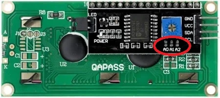
Now we wire the I2C LCD with Arduino. Connect the Vcc and GND pin of I2C LCD with Vcc and GND pin of Arduino. Next connect SCL (clock) and SDA (data) pins of I2C LCD to SCL and SDA pins of Arduino. SCL and SDA pins are the same as pins A5 and A4 Analog input pins of Arduino where pink and blue wires are connected with LCD. These header pins are also connected to A5 and A4 pins of Arduino.

When using I2C LCD, make sure A0, A1, A2 address jumpers are not shorted. As in Arduino code we will be using Address 0x27 for the I2C LCD which will only be formed when these jumpers are not shorted.
Connection between Arduino Uno and RFID Reader:
| RFID Side pin | Arduino Side Pin |
|---|---|
| SS (Pin 1) | 10 |
| SCK (pin 2) | 13 |
| MOSI (Pin 3) | 11 |
| MISO (Pin 4) | 12 |
| IRQ (pin 5) | Not Connected |
| GND (Pin6) | GND pin of Arduino |
| RST (pin 7) | 9 |
| VCC (pin 8) | 3.3 V pin of Arduino |
Connection between Arduino Uno and I2C LCD:
| LCD Pin | Arduino UNO |
|---|---|
| GND | GND |
| VCC | 5V |
| SDA | A4 |
| SCL | A5 |
Arduino Code to read all the Data of RFID Card
/*
Code to Read all data from RFID card and send it to UART port @ baudrate 115200,n,8,1
by platwithcircuit.com
*/
#include <LiquidCrystal_I2C.h>
  // Library to run I2C LCD
#include <SPI.h>
#include <MFRC522.h>

#define RST_PIN 9  // Configurable, see typical pin layout above
#define SS_PIN 10  // Configurable, see typical pin layout above

MFRC522 mfrc522(SS_PIN, RST_PIN);  // Create MFRC522 instance

// Set the LCD address to 0x27 for a 16 chars and 2 line display
LiquidCrystal_I2C lcd(0x27, 16, 2);

// this flag is used to check if previous card is removed or not
bool boIsPreviousCardRemoved = true;

void setup() {
  // initialize the LCD
  lcd.init();
  // Turn ON the Backlight
  lcd.backlight();
  // Clear the display buffer
  lcd.clear();

  // Print a message to the LCD
  lcd.setCursor(0, 0);
  lcd.print("Initializing");

  // Initialize serial communications with the PC
  Serial.begin(115200);
  while (!Serial);  // Do nothing if no serial port is opened

  SPI.begin();                        // Init SPI bus
  mfrc522.PCD_Init();                 // Init MFRC522
  delay(4);                           // Optional delay of 4 ms
  mfrc522.PCD_DumpVersionToSerial();  // Show details of PCD - MFRC522 i.e., RF Card Reader details
  Serial.println(F("Scan PICC to see UID, SAK, type, and data in the Card"));
 delay(1000);
  lcd.clear();
  lcd.setCursor(0, 0);
  lcd.print("Place Card on");
  lcd.setCursor(0, 1);
  lcd.print("Card Reader");
}

void loop() {
  // Make sure that previous card is removed before going ahead
  if ((mfrc522.PICC_IsNewCardPresent() == true) && (boIsPreviousCardRemoved == true)) {
    // Read Serial Data
    if (mfrc522.PICC_ReadCardSerial() == true) {
      lcd.clear();
      lcd.setCursor(0, 0);
      lcd.print("Card Detected");
      lcd.setCursor(0, 1);
      lcd.print("Keep it there...");
      // Dump debug info about the card; PICC_HaltA() is automatically called
      mfrc522.PICC_DumpToSerial(&(mfrc522.uid));
      delay(1000);
      lcd.clear();
      lcd.setCursor(0, 0);
      lcd.print("Remove Card From");
      lcd.setCursor(0, 1);
      lcd.print("Card Reader ");
      boIsPreviousCardRemoved = false;
      delay(2000);
    }
  } else {
    if (boIsPreviousCardRemoved == false) {
      lcd.clear();
      lcd.setCursor(0, 0);
      lcd.print("Place Card on");
      lcd.setCursor(0, 1);
      lcd.print("Card Reader");
      boIsPreviousCardRemoved = true;
    }
  }
}
Output

Code Explanation
The code begins by including three essential libraries. LiquidCrystal_I2C.h is used to operate the 16×2 LCD module via I2C communication. SPI.h is used to establish communication between the Arduino and RFID module using the SPI protocol. MFRC522.h provides functions to initialize, detect, and interact with RFID tags.
#include <LiquidCrystal_I2C.h>
  // Library to Run I2C LCD
#include <SPI.h>
#include <MFRC522.h>
The RFID module requires two control pins: SS (Slave Select) and RST (Reset) that are defined as digital pin 10 and pin 9 respectively. Now we create an object of the MFRC522 class named mfrc522 and initialize it with these pins.
Then we create an object named lcd from the LiquidCrystal_I2C class, using the I2C address 0x27 and define the LCD dimensions: 16 characters wide and 2 rows tall.
#define RST_PIN 9  // Configurable, see typical pin layout above
#define SS_PIN 10  // Configurable, see typical pin layout above

MFRC522 mfrc522(SS_PIN, RST_PIN);  // Create MFRC522 instance
// Set the LCD address to 0x27 for a 16 chars and 2 line display
LiquidCrystal_I2C lcd(0x27, 16, 2);
Next we initialize the boolean variable boIsPreviousCardRemoved as True.
// this flag is used to check if card is detected or not
bool boIsPreviousCardRemoved = True;
In the setup() function, first we initialize the LCD using lcd.init(), and then turn ON the LCD backlight using lcd.backlight(). The screen is cleared and a message “Initializing” is displayed to inform the user that the system is starting.
void setup() {
  // initialize the LCD
  lcd.init();
  // Turn ON the Backlight
  lcd.backlight();
  // Clear the display buffer
  lcd.clear();

  // Print a message to the LCD
  lcd.setCursor(0, 0);
  lcd.print("Initializing");
Next, serial communication is started at 115200 baud rate using Serial.begin(115200), which is useful for viewing card data on a serial monitor. The while (!Serial) ensures that the code waits until the Serial Monitor is opened.
Then we initialize the SPI communication required for the RC522 module using SPI.begin(). Then we initialize RFID reader using mfrc522.PCD_Init(). A short 4 ms delay is added for hardware stabilization.
// Initialize serial communications with the PC
  Serial.begin(115200);
  while (!Serial);  // Do nothing if no serial port is opened

  SPI.begin();                        // Init SPI bus
  mfrc522.PCD_Init();                 // Init MFRC522
  delay(4);                           // Optional delay of 4 ms
Then we print the technical information about the RFID module to the serial monitor using PCD_DumpVersionToSerial(). Then, the LCD is cleared and updated to show instructions: “Place Card on” (first line) and “Card Reader” (second line), letting the user know the system is ready to scan a tag.
mfrc522.PCD_DumpVersionToSerial();  // Show details of PCD - MFRC522 i.e RF Card Reader details
  Serial.println(F("Scan PICC to see UID, SAK, type, and data in the Card"));

  lcd.clear();
  lcd.setCursor(0, 0);
  lcd.print("Place Card on");
  lcd.setCursor(0, 1);
  lcd.print("Card Reader");
}
The loop() function runs continuously and checks if a new RFID card is present using PICC_IsNewCardPresent(). If a card is detected and the boIsPreviousCardRemoved flag is true (i.e., a new card has been presented), it proceeds to read the card’s serial number using PICC_ReadCardSerial(). If successful, the LCD is updated to show “Card Detected” and “Keep it there…”, instructing the user to hold the card in place.
void loop() {
  // Make sure that previous card is removed before going ahead
  if ((mfrc522.PICC_IsNewCardPresent() == true) && (boIsPreviousCardRemoved == true)) {
    // Read Serial Data
    if (mfrc522.PICC_ReadCardSerial() == true) {
      lcd.clear();
      lcd.setCursor(0, 0);
      lcd.print("Card Detected");
      lcd.setCursor(0, 1);
      lcd.print("Keep it there...");
Then we call PICC_DumpToSerial() to dump detailed information about the RFID card—like UID, SAK, type, and memory block contents—to the serial monitor.
After a short delay to allow users to read the message properly, the LCD is updated again to request the user to remove the card. At this point, the boIsPreviousCardRemoved flag is set to false, ensuring that the card will not be scanned again until removed. A 2-second delay is added for stability and user readability.
// Dump debug info about the card; PICC_HaltA() is automatically called
      mfrc522.PICC_DumpToSerial(&(mfrc522.uid));
      delay(1000);
      lcd.clear();
      lcd.setCursor(0, 0);
      lcd.print("Remove Card From");
      lcd.setCursor(0, 1);
      lcd.print("Card Reader ");
      boIsPreviousCardRemoved = false;
      delay(2000);
    }
  }
If the RFID module does not detect a new card and the boIsPreviousCardRemoved flag is false, then the LCD is reset to its original state, showing the message “Place Card on” and “Card Reader” again. The flag boIsPreviousCardRemoved is reset to true, allowing the system to scan the next card when presented.
else {
    if (boIsPreviousCardRemoved == false) {
      lcd.clear();
      lcd.setCursor(0, 0);
      lcd.print("Place Card on");
      lcd.setCursor(0, 1);
      lcd.print("Card Reader");
      boIsPreviousCardRemoved = true;
    }
  }
}
Arduino Code to Read/Write Data on RFID Card
This Arduino sketch allows you to write data to an RFID card. The LCD provides real-time status, and the full card data is printed to the serial monitor. The serial monitor is also used to send the required data to Arduino. The serial monitor should operate at baud 115200,n,8,1.
/*
Code to get data from the UART (@baud 115200) and write it on the specified block
by www.playwithcircuit.com
*/

#include <SPI.h>
#include <MFRC522.h>
  // Header of Library to run RFID card
#include <LiquidCrystal_I2C.h>
  // Header of Library to run I2C LCD

#define SS_PIN 10
#define RST_PIN 9

MFRC522 rfid(SS_PIN, RST_PIN);
MFRC522::MIFARE_Key key;

// Set the LCD address to 0x27 for 16 chars and 2 line display
LiquidCrystal_I2C lcd(0x27, 16, 2);

bool oneTimeFlag = false;

void setup() {
  // initialize the LCD
  lcd.init();
  // Turn ON the Backlight
  lcd.backlight();
  // Clear the display buffer
  lcd.clear();

  Serial.begin(115200);
  SPI.begin();
  rfid.PCD_Init();
  Serial.println("\nRFID Write Tool Ready");

  // Use default key (factory value) , its 0xFF
  for (byte i = 0; i < 6; i++) {
    key.keyByte[i] = 0xFF;
  }

  lcd.clear();
  lcd.setCursor(0, 0);
  lcd.print("Place Card on");
  lcd.setCursor(0, 1);
  lcd.print("Card Reader");
  delay(1000);
}

// this functions checks if we are writing into the wrong block or right block
bool isWritableBlock(byte block) {
  if (block == 0) return false;            // Block 0 is UID (DO NOT WRITE)
  if ((block + 1) % 4 == 0) return false;  // Sector trailer (DO NOT WRITE)
  return true;
}

void loop() {
  byte writeBuffer[18] = { 0 };
  byte readBuffer[16] = { 0 };
  byte sizeofWriteBuffer = sizeof(writeBuffer);
  byte bytestobeRead;
  byte bytesRead;
  byte sector;
  MFRC522::StatusCode status;
  byte blockNum;
  byte trailerBlock;

  // the flag makes sure that lcd is updated only once
  if (oneTimeFlag == false) {
    lcd.clear();
    lcd.setCursor(0, 0);
    lcd.print("Place Card on");
    lcd.setCursor(0, 1);
    lcd.print("Card Reader");
    oneTimeFlag = true;
  }

  // Look for new card
  if (!rfid.PICC_IsNewCardPresent() || !rfid.PICC_ReadCardSerial()) return;

  oneTimeFlag = false;

  lcd.clear();
  lcd.setCursor(0, 0);
  lcd.print("Card Detected");
  lcd.setCursor(0, 1);
  lcd.print("Keep it there...");

  delay(1000);

  // Print UID
  Serial.print("Card UID: ");
  lcd.clear();
  lcd.setCursor(0, 0);
  lcd.print("Card UID :");
  lcd.setCursor(0, 1);
  for (byte i = 0; i < rfid.uid.size; i++) {
    Serial.print(rfid.uid.uidByte[i] < 0x10 ? " 0" : " ");
    Serial.print(rfid.uid.uidByte[i], HEX);
    lcd.print(rfid.uid.uidByte[i] < 0x10 ? " 0" : " ");
    lcd.print(rfid.uid.uidByte[i], HEX);
  }
  Serial.println();
  delay(3000);

  // flush serial input before getting new data
  while (Serial.available()) {
    Serial.read();
  }

  do {
    lcd.clear();
    lcd.setCursor(0, 0);
    lcd.print("Enter Block No: ");
    Serial.println("Enter block number to write (0-63): ");
    while (!Serial.available())
      ;
    blockNum = Serial.parseInt();
    Serial.read();  // Consume leftover '\n'

    if (!isWritableBlock(blockNum)) {
      Serial.println("This block is not writable");
      lcd.setCursor(0, 1);
      lcd.print("Invalid Block No");
      delay(1000);
    } else {
      lcd.setCursor(0, 1);
      lcd.print(blockNum);
      delay(1000);
      break;
    }
  } while (1);

  // flush serial input before getting new data
  while (Serial.available()) {
    Serial.read();
  }

  do {
    lcd.clear();
    lcd.setCursor(0, 0);
    lcd.print("Enter bytes no.:");
    Serial.println("Enter number of bytes to write (1-16): ");
    while (!Serial.available())
      ;
    bytestobeRead = Serial.parseInt();
    Serial.read();  // Consume leftover '\n'

    if (bytestobeRead < 1 || bytestobeRead > 16) {
      Serial.println("\nInvalid byte count.");
      lcd.setCursor(0, 1);
      lcd.print("Invalid bytes no");
      delay(1000);
    } else {
      lcd.setCursor(0, 1);
      lcd.print(bytestobeRead);
      delay(1000);
      break;
    }
  } while (1);

  // flush serial input before getting new data
  while (Serial.available()) {
    Serial.read();
  }

  do {
    // set the timeout for read operation, its 60 seconds
    Serial.setTimeout(60000);
    lcd.clear();
    lcd.setCursor(0, 0);
    lcd.print("Enter Data : ");
    Serial.print("Enter your Data : ");
    while (Serial.available()) Serial.read();  // Clear buffer

    memset(readBuffer, 0x00, 16);
    // Read and store the specified number
    bytesRead = Serial.readBytes(readBuffer, bytestobeRead);
    readBuffer[bytesRead] = '\0';  // Add null terminator after last byte

    if (bytesRead > 0) {
      lcd.setCursor(0, 1);
      lcd.print((char *)readBuffer);
      delay(1000);
      break;
    } else {
      Serial.println("\nNo Data Received.");
    }
  } while (1);

  // Authenticate block
  sector = blockNum / 4;          // find the sector number from the block number
  trailerBlock = sector * 4 + 3;  // finf=d the trailer block of the particular sector

  status = rfid.PCD_Authenticate(MFRC522::PICC_CMD_MF_AUTH_KEY_A, trailerBlock, &key, &(rfid.uid));
  if (status != MFRC522::STATUS_OK) {
    Serial.print("Authentication failed: ");
    Serial.println(rfid.GetStatusCodeName(status));
    rfid.PICC_HaltA();
    rfid.PCD_StopCrypto1();
    lcd.clear();
    lcd.setCursor(0, 0);
    lcd.print("Authen. failed: ");
    lcd.setCursor(0, 1);
    lcd.print(rfid.GetStatusCodeName(status));
    delay(1000);
    return;
  } else {
    lcd.clear();
    lcd.setCursor(0, 0);
    lcd.print("Authentication");
    lcd.setCursor(0, 1);
    lcd.print("Successful");
    delay(3000);
  }

  // From Here Onwards Secured Session Starts
  // Read complete block , here 18 bytes are used because along with 16 bytes two bytes CRC is also read which is internally calculated and then sent
  memset(writeBuffer, 0x00, sizeofWriteBuffer);

  status = rfid.MIFARE_Read(blockNum, writeBuffer, &sizeofWriteBuffer);
  if (status == MFRC522::STATUS_OK) {
    // Edit Required data
    memcpy(writeBuffer, readBuffer, bytesRead);
    // Write complete block 16 bytes , as bytes less than or greater than block size can't be written
    status = rfid.MIFARE_Write(blockNum, writeBuffer, 16);
    if (status == MFRC522::STATUS_OK) {
      Serial.println("Data written successfully.");
      lcd.clear();
      lcd.setCursor(0, 0);
      lcd.print("Data Written");
      lcd.setCursor(0, 1);
      lcd.print("Successfully");
      delay(3000);
    } else {
      Serial.print("Write failed: ");
      Serial.println(rfid.GetStatusCodeName(status));
      lcd.clear();
      lcd.setCursor(0, 0);
      lcd.print("Write failed: ");
      lcd.setCursor(0, 1);
      lcd.print(rfid.GetStatusCodeName(status));
      delay(3000);
      return;
    }
  } else {
    Serial.print("Read Failed: ");
    Serial.println(rfid.GetStatusCodeName(status));
    lcd.clear();
    lcd.setCursor(0, 0);
    lcd.print("Read failed: ");
    lcd.setCursor(0, 1);
    lcd.print(rfid.GetStatusCodeName(status));
    delay(3000);
    return;
  }

   if (status == MFRC522::STATUS_OK) {
    memset(writeBuffer, 0x00, sizeofWriteBuffer);
    status = rfid.MIFARE_Read(blockNum, writeBuffer, &sizeofWriteBuffer);
    if (status == MFRC522::STATUS_OK) {
      Serial.print("\nHere New data at block ");
      Serial.print(blockNum);
      Serial.print(" is :");
      Serial.write(writeBuffer, 16);
      lcd.clear();
      lcd.setCursor(0, 0);
      lcd.print("Updated data at");
      lcd.setCursor(0, 1);
      lcd.print("block ");
      lcd.print(blockNum);
      lcd.print(" is:");
      delay(2000);
      lcd.clear();
      lcd.setCursor(0, 0);
      for (int i = 0; i < 16; i++) {
        lcd.write(writeBuffer[i]);  // prints raw bytes, one by one
      }
      delay(3000);
    }
  }

  // Halting connection with RFID card
  rfid.PICC_HaltA();

  // End session
  rfid.PCD_StopCrypto1();

  lcd.clear();
  lcd.setCursor(0, 0);
  lcd.print("Remove Card From");
  lcd.setCursor(0, 1);
  lcd.print("Card Reader ");
  delay(2000);
}
Output
Code Explanation
The code begins by including three libraries:
- LiquidCrystal_I2C.h to control a 16×2 LCD using the I2C interface.
- SPI.h to enable communication between the Arduino and the RC522 RFID module using the SPI protocol.
- MFRC522.h which contains all the necessary functions to interact with RFID cards such as detecting, authenticating, reading, and writing data.
#include <SPI.h>
#include <MFRC522.h>
  // Header of Library to run RFID card
#include <LiquidCrystal_I2C.h>
  // Header of Library to Run I2C LCD
Now we define the RFID module’s SS pin as pin 10, and the Reset (RST) pin as pin 9. These are passed into an MFRC522 object named rfid, which is used throughout the program to perform RFID-related operations.
Next we create a key object of type MFRC522::MIFARE_Key to store the 6-byte authentication key (default is 0xFF for new cards). Additionally, a LiquidCrystal_I2C object is created to manage a 16×2 LCD connected via I2C with address 0x27.
oneTimeFlag is used so that the LCD screen doesn’t keep printing the same message (Place Card on Reader) again and again when no card is present. It shows the message just once and waits for a card. Once a card is scanned, the flag is reset, the message can appear again next time. This makes the display cleaner and avoids flickering.
#define SS_PIN 10
#define RST_PIN 9

MFRC522 rfid(SS_PIN, RST_PIN);
MFRC522::MIFARE_Key key;

// Set the LCD address to 0x27 for a 16 chars and 2 line display
LiquidCrystal_I2C lcd(0x27, 16, 2);

bool oneTimeFlag = false;
In the setup() function, first we initialize the LCD, turn ON its backlight, and clear the display. Then, serial communication starts at 115200 baud rate. The RFID module is also initialized.
The key array holds six 0xFF bytes, which is the default key for MIFARE RFID cards. The LCD then prompts the user with the message “Place Card on Card Reader”, indicating the system is ready to scan a card.
void setup() {
  // initialize the LCD
  lcd.init();
  // Turn ON the Backlight
  lcd.backlight();
  // Clear the display buffer
  lcd.clear();

  Serial.begin(115200);
  SPI.begin();
  rfid.PCD_Init();
  Serial.println("\nRFID Write Tool Ready");

  // Use default key (factory value) , its 0xFF
  for (byte i = 0; i < 6; i++) {
    key.keyByte[i] = 0xFF;
  }

  lcd.clear();
  lcd.setCursor(0, 0);
  lcd.print("Place Card on");
  lcd.setCursor(0, 1);
  lcd.print("Card Reader");
  delay(1000);
}
Next we define a function isWritableBlock() to check whether a block number is safe for writing. It prevents writing to:
- Block 0 (contains the card UID)
- Sector trailer blocks (every 4th block like 3, 7, 11…) that store access permissions and keys
This function ensures data integrity and prevents accidentally disabling card sectors.
// this functions checks if we are writing into the wrong block or right block
bool isWritableBlock(byte block) {
  if (block == 0) return false;            // Block 0 is UID (DO NOT WRITE)
  if ((block + 1) % 4 == 0) return false;  // Sector trailer (DO NOT WRITE)
  return true;
}
The loop() function handles the entire card interaction process.
byte writeBuffer[18] = {0} array stores data before writing it to the RFID card. It’s 18 bytes to allow space for 16 data bytes and 2 extra bytes (used for CRC or safety).
byte readBuffer[16] = {0} array holds the actual data that will be written (from user input).
byte sizeofWriteBuffer = sizeof(writeBuffer) stores the size (18) of the writeBuffer, used later when reading from the card.
byte bytestobeRead holds how many bytes the user wants to write (between 1 and 16).
byte bytesRead stores how many bytes were actually received from the user through Serial.
byte sector is the sector number of the block selected (each sector has 4 blocks).
MFRC522::StatusCode status used to store the result (success/failure) of RFID operations like read, write, and authenticate.
byte blockNum stores the block number the user wants to write to (0 to 63).
byte trailerBlock Holds the trailer block number, which is the last block in each sector and is needed for authentication.
  byte writeBuffer[18] = { 0 };
  byte readBuffer[16] = { 0 };
  byte sizeofWriteBuffer = sizeof(writeBuffer);
  byte bytestobeRead;
  byte bytesRead;
  byte sector;
  MFRC522::StatusCode status;
  byte blockNum;
  byte trailerBlock;
A flag oneTimeFlag ensures the LCD displays the initial message only once unless the card is removed and reinserted.
 // the flag makes sure that lcd is updated only once
  if (oneTimeFlag == false) {
    lcd.clear();
    lcd.setCursor(0, 0);
    lcd.print("Place Card on");
    lcd.setCursor(0, 1);
    lcd.print("Card Reader");
    oneTimeFlag = true;
  }
Now we check two things:
- Is there a new RFID card present near the reader?
PICC_IsNewCardPresent()returns true if a new card has been detected.- Can the card’s UID (unique ID) be read?
PICC_ReadCardSerial()fetches the card’s UID into memory.
If either check fails, the function exits early (return;) and the loop starts over. This prevents the rest of the code from running unless a card is detected.
oneTimeFlag = false resets a flag that was used earlier to display “Place Card on Reader” only once. By setting it to false here, it ensures that the message will appear again after the card is removed.
Once a card is successfully read, the LCD is cleared and it shows: “Card Detected” on the first line and “Keep it there…” on the second line, asking the user not to remove the card yet, as read/write operations will begin shortly.
Then we add a 1-second pause (1000 milliseconds), giving the user enough time to see the message
 // Look for new card
  if (!rfid.PICC_IsNewCardPresent() || !rfid.PICC_ReadCardSerial()) return;

  oneTimeFlag = false;

  lcd.clear();
  lcd.setCursor(0, 0);
  lcd.print("Card Detected");
  lcd.setCursor(0, 1);
  lcd.print("Keep it there...");

  delay(1000);
Next, we print the UID bytes in hexadecimal to both the Serial Monitor and the LCD. A 3-second delay is added to allow the user to view the UID before the next step begins.
  // Print UID
  Serial.print("Card UID: ");
  lcd.clear();
  lcd.setCursor(0, 0);
  lcd.print("Card UID :");
  lcd.setCursor(0, 1);
  for (byte i = 0; i < rfid.uid.size; i++) {
    Serial.print(rfid.uid.uidByte[i] < 0x10 ? " 0" : " ");
    Serial.print(rfid.uid.uidByte[i], HEX);
    lcd.print(rfid.uid.uidByte[i] < 0x10 ? " 0" : " ");
    lcd.print(rfid.uid.uidByte[i], HEX);
  }
  Serial.println();
  delay(3000);
Now any leftover serial input is cleared to avoid reading old data. Then, the user is prompted via Serial Monitor and LCD to enter a block number (0–63) where the data will be written.
The program waits for the user input, reads it using Serial.parseInt(), and stores it in blockNum. The Serial.read() clears the newline character (‘\n’) left in the input buffer after the user presses Enter.
// flush serial input before getting new data
  while (Serial.available()) {
    Serial.read();
  }

  do {
    lcd.clear();
    lcd.setCursor(0, 0);
    lcd.print("Enter Block No: ");
    Serial.println("Enter block number to write (0-63): ");
    while (!Serial.available())
      ;
    blockNum = Serial.parseInt();
    Serial.read();  // Consume leftover '\n'
The program checks if the entered block number is valid and writable using the isWritableBlock() function. If it’s not, an error message is shown on both the LCD and Serial Monitor. If valid, the loop breaks and proceeds.
It then flushes the Serial buffer again and prompts the user to enter the number of bytes to write (1–16). It waits for input, stores the value in bytestobeRead, and clears the newline character to prepare for clean data entry in the next step.
 if (!isWritableBlock(blockNum)) {
      Serial.println("This block is not writable");
      lcd.setCursor(0, 1);
      lcd.print("Invalid Block No");
      delay(1000);
    } else {
      lcd.setCursor(0, 1);
      lcd.print(blockNum);
      delay(1000);
      break;
    }
  } while (1);

  // flush serial input before getting new data
  while (Serial.available()) {
    Serial.read();
  }

  do {
    lcd.clear();
    lcd.setCursor(0, 0);
    lcd.print("Enter bytes no.:");
    Serial.println("Enter number of bytes to write (1-16): ");
    while (!Serial.available())
      ;
    bytestobeRead = Serial.parseInt();
    Serial.read();  // Consume leftover '\n'
Next the program validates the number of bytes the user wants to write to the RFID card. If the entered value is less than 1 or greater than 16, an error message is shown on both the Serial Monitor and LCD. If valid, it displays the byte count on the LCD and exits the loop to proceed with data entry.
 if (bytestobeRead < 1 || bytestobeRead > 16) {
      Serial.println("\nInvalid byte count.");
      lcd.setCursor(0, 1);
      lcd.print("Invalid bytes no");
      delay(1000);
    } else {
      lcd.setCursor(0, 1);
      lcd.print(bytestobeRead);
      delay(1000);
      break;
    }
  } while (1);
Now the system is prepared to receive user input data for writing to the RFID card. It first clears any leftover data in the serial buffer to avoid conflicts. Then, it sets a 60-second timeout to give the user enough time to enter the data. The LCD displays “Enter Data :” and the Serial Monitor prompts the same.
The read buffer is cleared with memset(), ensuring no leftover values.
Serial.readBytes() reads the exact number of bytes specified earlier and stores them in readBuffer, followed by adding a null terminator (\0).
// flush serial input before getting new data
  while (Serial.available()) {
    Serial.read();
  }

  do {
    // set the timeout for read operation, its 60 seconds
    Serial.setTimeout(60000);
    lcd.clear();
    lcd.setCursor(0, 0);
    lcd.print("Enter Data : ");
    Serial.print("Enter your Data : ");
    while (Serial.available()) Serial.read();  // Clear buffer

    memset(readBuffer, 0x00, 16);
    // Read and store the specified number
    bytesRead = Serial.readBytes(readBuffer, bytestobeRead);
    readBuffer[bytesRead] = '\0';  // Add null terminator after last byte
Next, the program checks if the user has entered any data. If bytesRead > 0, it means data was successfully received from the Serial Monitor. The data is then displayed on the second line of the LCD for confirmation, followed by a short delay. If no data was received, an error message “No Data Received” is printed in the Serial Monitor, and the loop continues, prompting the user again.
  if (bytesRead > 0) {
      lcd.setCursor(0, 1);
      lcd.print((char *)readBuffer);
      delay(1000);
      break;
    } else {
      Serial.println("\nNo Data Received.");
    }
  } while (1);
Next this program authenticates the RFID card before writing data. First, it calculates the sector number and identifies the corresponding trailer block (used for authentication). Then, it calls PCD_Authenticate() function using the default key (0xFF) to gain access. If authentication fails, an error message is shown on the Serial Monitor and LCD, and the operation is halted. If successful, a confirmation message “Authentication Successful” is displayed, allowing the program to proceed with the secure write operation.
 // Authenticate block
  sector = blockNum / 4;          // find the sector number from the block number
  trailerBlock = sector * 4 + 3;  // finf=d the trailer block of the particular sector

  status = rfid.PCD_Authenticate(MFRC522::PICC_CMD_MF_AUTH_KEY_A, trailerBlock, &key, &(rfid.uid));
  if (status != MFRC522::STATUS_OK) {
    Serial.print("Authentication failed: ");
    Serial.println(rfid.GetStatusCodeName(status));
    rfid.PICC_HaltA();
    rfid.PCD_StopCrypto1();
    lcd.clear();
    lcd.setCursor(0, 0);
    lcd.print("Authen. failed: ");
    lcd.setCursor(0, 1);
    lcd.print(rfid.GetStatusCodeName(status));
    delay(1000);
    return;
  } else {
    lcd.clear();
    lcd.setCursor(0, 0);
    lcd.print("Authentication");
    lcd.setCursor(0, 1);
    lcd.print("Successful");
    delay(3000);
  }
Now the secured data write operation starts. It first clears the writeBuffer using memset() to remove old data. Then MIFARE_Read() reads the existing data (18 bytes: 16 data + 2 CRC) from the specified block.
If reading succeeds, memcpy() updates the buffer with the new user-entered data.
Then MIFARE_Write() writes exactly 16 bytes to the specified block. If writing is successful, a success message is displayed; otherwise, a write error is shown. If the read fails, it also displays an error and exits the loop.
  // From Here Onwards Secured Session Starts
  // Read complete block, here 18 bytes are used because along with 16 bytes two bytes CRC is also read which is internally calculated and then sent
  memset(writeBuffer, 0x00, sizeofWriteBuffer);

  status = rfid.MIFARE_Read(blockNum, writeBuffer, &sizeofWriteBuffer);
  if (status == MFRC522::STATUS_OK) {
    // Edit Required data
    memcpy(writeBuffer, readBuffer, bytesRead);
    // Write complete block 16 bytes , as bytes less than or greater than block size can't be written
    status = rfid.MIFARE_Write(blockNum, writeBuffer, 16);
    if (status == MFRC522::STATUS_OK) {
      Serial.println("Data written successfully.");
      lcd.clear();
      lcd.setCursor(0, 0);
      lcd.print("Data Written");
      lcd.setCursor(0, 1);
      lcd.print("Successfully");
      delay(3000);
    } else {
      Serial.print("Write failed: ");
      Serial.println(rfid.GetStatusCodeName(status));
      lcd.clear();
      lcd.setCursor(0, 0);
      lcd.print("Write failed: ");
      lcd.setCursor(0, 1);
      lcd.print(rfid.GetStatusCodeName(status));
      delay(3000);
      return;
    }
  } else {
    Serial.print("Read Failed: ");
    Serial.println(rfid.GetStatusCodeName(status));
    lcd.clear();
    lcd.setCursor(0, 0);
    lcd.print("Read failed: ");
    lcd.setCursor(0, 1);
    lcd.print(rfid.GetStatusCodeName(status));
    delay(3000);
    return;
  }
Finally the full content of the complete block is printed to the Serial Monitor and displayed on the I2C LCD. Once data is displayed, the code halts communication with the RFID card using rfid.PICC_HaltA(). Then, rfid.PCD_StopCrypto1() ends the secure authentication session. Finally, a user instruction is displayed on the LCD to prompt removal of the card from the reader.
   if (status == MFRC522::STATUS_OK) {
    memset(writeBuffer, 0x00, sizeofWriteBuffer);
    status = rfid.MIFARE_Read(blockNum, writeBuffer, &sizeofWriteBuffer);
    if (status == MFRC522::STATUS_OK) {
      Serial.print("\nHere New data at block ");
      Serial.print(blockNum);
      Serial.print(" is :");
      Serial.write(writeBuffer, 16);
      lcd.clear();
      lcd.setCursor(0, 0);
      lcd.print("Updated data at");
      lcd.setCursor(0, 1);
      lcd.print("block ");
      lcd.print(blockNum);
      lcd.print(" is:");
      delay(2000);
      lcd.clear();
      lcd.setCursor(0, 0);
      for (int i = 0; i < 16; i++) {
        lcd.write(writeBuffer[i]);  // prints raw bytes, one by one
      }
      delay(3000);
    }
  }

  // Halting connection with RFID card
  rfid.PICC_HaltA();

  // End session
  rfid.PCD_StopCrypto1();

  lcd.clear();
  lcd.setCursor(0, 0);
  lcd.print("Remove Card From");
  lcd.setCursor(0, 1);
  lcd.print("Card Reader ");
  delay(2000);
}
