
Character LCDs have long been the default choice for adding visual output to Arduino projects. They’re simple, reliable, and familiar—but they also come with some limitations. Fixed character grids, less visual capability and bulky form factors often restrict how information can be displayed.
This is where OLED graphic displays come into play. They are modern, ultra-thin, and extremely lightweight, offering high contrast and crisp visuals that are easy to read even in low-light conditions. More importantly, OLED gives you complete control over every pixel on the screen, so you can display anything from sensor graphs and progress bars to small animations and custom bitmap images.
In this tutorial, you’ll learn how to interface an OLED graphic display with Arduino. We’ll first display text, then draw geometric shapes and finally display custom images.
OLED Display – Overview
OLED displays are available in a wide range of configurations. They come in various sizes, such as 128×64 pixels and 128×32 pixels and also come in different color options, including white, blue, dual-color combinations and RGB. They also support different communication interfaces— some use I2C for simple connections, while others use SPI for faster data transfer.
In this tutorial, we are using both I2C and SPI versions of a 0.96-inch 128×64 OLED display. Both of these OLEDs have the same controller SSD1306. This controller acts as the core processing unit of the display. It receives commands and data from the microcontroller and translates them into signals that control the individual OLED pixels.
SSD1306 includes internal memory buffering, which means the display stores the image data internally rather than relying on the microcontroller to refresh each pixel continuously.
OLED pixels emit their own light, so there is no need for a backlight, unlike traditional LCD displays. This results in higher contrast, deeper black levels, and wider viewing angles while also reducing power consumption. Typical OLED modules draw around 20 mA, making them highly suitable for battery-powered and portable applications.
Most OLED modules are designed to operate within a voltage range of 3.3V to 5V, and many include an onboard voltage regulator that allows safe connection to 5V microcontrollers like the Arduino UNO.
I2C OLED Module Hardware Overview

An I2C OLED display module integrates several components on its PCB.
Connector The connector is the interface between the OLED module and the external microcontroller. This is typically a 4-pin or 7-pin header depending on whether the module supports I2C, SPI, or both. Through this connector, the module receives power (VCC and GND) and communication signals such as SDA/SCL for I2C or CLK, MOSI, CS, DC, and RES for SPI. The connector is designed to make the module plug-and-play, allowing it to be easily wired using jumper wires or soldered directly onto a PCB.
3.3V Voltage Regulator The 3.3V voltage regulator is used to step down the input voltage supplied to the OLED module. It converts 5V input to a stable 3.3V output, allowing the module to be safely powered from 5V sources.
I2C Address Select Jumper The I2C address select jumper allows the I2C address of the OLED module to be configured. The SSD1306 controller supports two different I2C addresses, typically 0x3C and 0x3D in 7-bit format. When address 0x3C is bitwise left shifted by 1 then it becomes 0x78 in 8-bit format and when 0x3D is bitwise left shifted by 1 it becomes 0x7A in 8-bit format. Since the jumper is connected to the side where 0x78 is written hence in code address 0x3C should be used. . By default, the jumper is set to one address. Changing the jumper connection modifies the logic level of the address select pin, thereby changing the I2C address.
Pin Swap Jumper It is used to alter the pin configuration of the module. This improves compatibility with various development boards and wiring conventions without requiring external adapters or PCB modifications.
Resistors and Capacitors It consists of several surface-mount resistors and capacitors placed around the SSD1306 controller. These components perform several essential functions. The capacitors provide power supply decoupling and noise filtering, ensuring clean and stable voltage for the controller and the OLED panel. Pull-up resistors are used on the SDA and SCL lines to ensure proper I2C communication. Other resistors configure operating modes and stabilize logic levels.
OLED Connector The OLED connector is a flat-flex connector that links the OLED glass panel to the PCB. This connector carries multiple high-density signals from the SSD1306 controller directly to the OLED pixels. This connector is factory-mounted and should not be disconnected or bent, as it directly interfaces with the fragile display panel.
SPI OLED Module Hardware Overview

In an SPI OLED display, the OLED connector, and SSD1306 controller remain the same as in I2C OLED modules. Unlike I2C displays, which typically use 4 pins, this SPI OLED uses a 6-pin connector. These extra pins are required for SPI communication and control. Along with power and data lines, you’ll find additional control pins like CS and DC. These give direct control over how data is sent to the display.
Another key difference is that SPI OLED modules do not require pull-up resistors for communication lines, as SPI uses direct push-pull signaling instead of an open-drain bus. As a result, the resistor network on the PCB is populated differently compared to I2C OLED modules.
Understanding the OLED Memory Map
To control what to display on an OLED, it is important to understand how the display stores and organizes pixel data internally. OLED displays based on the SSD1306 controller do not draw graphics directly from the microcontroller’s memory. Instead, the controller uses its own dedicated memory to hold the pixel information that is shown on the screen.
Inside every SSD1306-based OLED module is 1KB (1024 bytes) of internal memory, known as Graphic Display Data RAM (GDDRAM). This memory acts as a frame buffer for the display. Each bit stored in the GDDRAM represents the ON or OFF state of a single pixel on the OLED panel. When the microcontroller sends data to the display, it is written into this memory, and the SSD1306 continuously refreshes the screen using the stored pixel pattern.
The memory is organized in the following structure:
It is divided into eight pages, numbered from Page 0 to Page 7.
Each page spans the full width of the display and consists of 128 columns, sometimes referred to as segments.
Each column within a page controls eight vertical pixels.
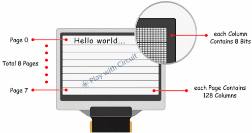
The total memory calculation becomes straightforward:
8 pages × 128 columns × 8 bits = 8,192 bits = 1,024 bytes = 1KB of memory
![]()
Technical Specifications
| Display Technology | OLED (Organic LED) |
| Operating Voltage | 3.3V – 5V |
| Screen Size | 0.96 Inch Across |
| Resolution | 128×64 pixels |
| Operating Current | 20mA max |
❕Note
All SSD1306 OLED modules contain the same 1KB of GDDRAM, regardless of the display’s physical resolution. A 128×64 OLED display utilizes all eight pages of memory, while a 128×32 OLED display uses only the first four pages. The remaining memory is present but unused. Because of this memory architecture, the same display libraries and code structure can be reused across different OLED sizes with minimal modification.
I2C OLED Display Module Pinout
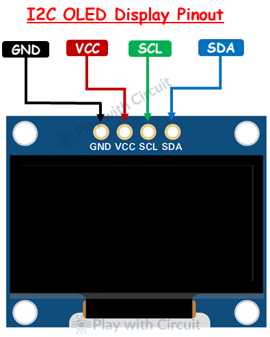
GND This is the ground pin. It must be connected to the ground pin of the Arduino.
VCC The VCC pin is a power supply pin. Most SSD1306-based OLED modules are designed to operate within a voltage range of 3.3V to 5V.
SCL The SCL pin is the serial clock pin used for I2C communication.
SDA The SDA pin is the serial data line used in I2C communication. It is responsible for transmitting both command data and pixel information from the microcontroller to the OLED display controller.
SPI OLED Display Module Pinout
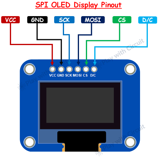
GND This is the ground pin.
VCC The VCC pin is the power supply pin for the OLED display module.
SCK This is the SPI clock pin. It carries the clock signal generated by the microcontroller, which synchronizes data transmission between the Arduino and the OLED display.
MOSI This pin is used to send data from the microcontroller to the OLED display. This pin transfers both command data and pixel information serially.
CS This pin enables or disables communication with the OLED display.
D/C This pin selects whether the data being sent is a command or display data. When the pin is LOW, the incoming bytes are interpreted as commands. When the pin is HIGH, the incoming data is treated as pixel information and written into display memory.
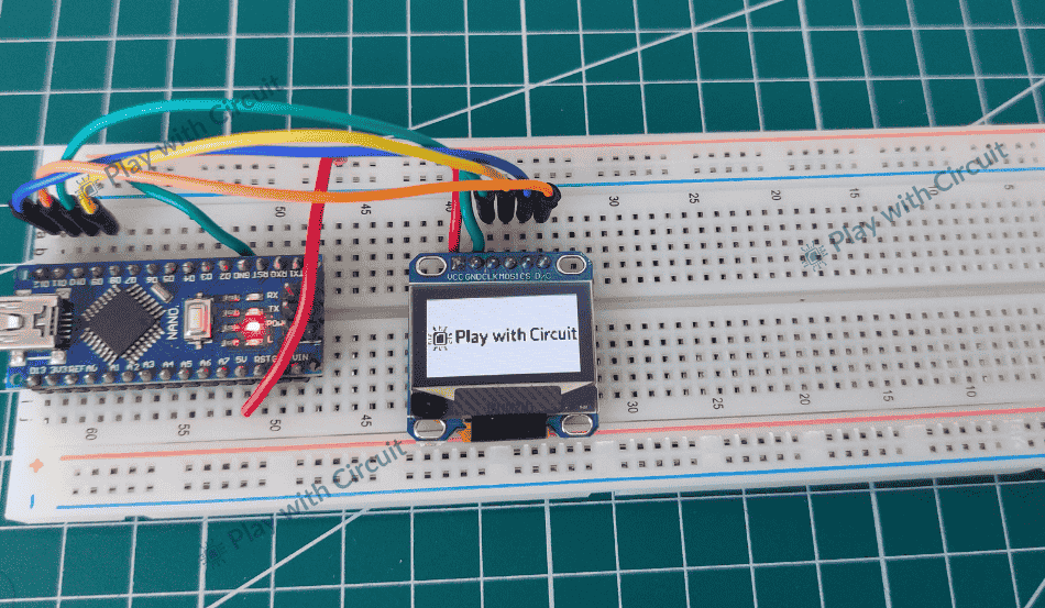
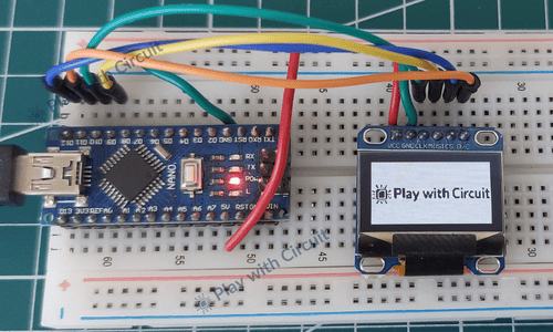
Wiring an OLED Display Module to Arduino
Now let’s connect the I2C and SPI OLED display to the Arduino Nano.
Hardware Requirement
| Component Name | Quantity | Remarks | Where to Buy |
|---|---|---|---|
| Arduino Nano | 1 | Revision R3 | Amazon |
| I2C OLED 128x64 | 1 | Should have SSD1306 OLED driver | Amazon |
| SPI OLED 128x64 | 1 | Should have SSD1306 OLED driver | Amazon |
| USB Cable type USB A to Mini B | 1 | For programming Arduino Nano | Amazon |
| Jumper Wires | Multiple | For connections | Amazon |
| 5V Supply Adapter | 1 | For providing power to Arduino Nano | Amazon |
Software Requirement
- Arduino IDE, Version 2.3.4 or above installed on your PC.
- Adafruit SSD1306 library
I2C OLED Display Wiring
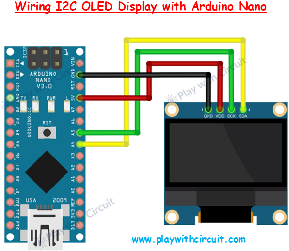
In the above diagram, the OLED display is connected to the Arduino Nano using only four wires. The VDD (or VCC) pin of the OLED is connected to the 5V pin of the Arduino Nano. The GND pin of the OLED is connected to the GND of the Arduino.
For communication, the OLED uses the I2C protocol, which operates on two lines: SCK (clock) and SDA (data). The SCK pin of the OLED is connected to A5, and the SDA pin is connected to A4 of the Arduino Nano.
SPI OLED Display Wiring
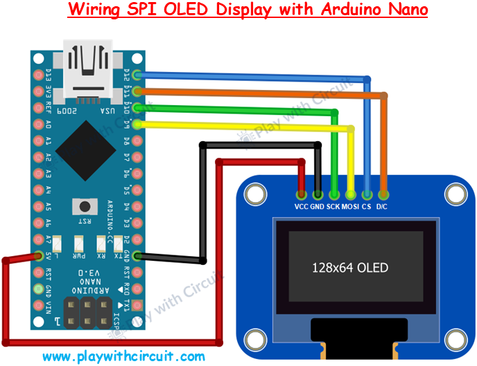
The SPI OLED display uses more pins compared to I2C because SPI provides direct and faster communication with dedicated signal lines.
The VCC pin of the OLED is connected to the 5V pin of the Arduino Nano, and the GND pin of the OLED is connected to GND pin of the Arduino Nano.
For communication, SPI uses multiple lines. The SCK (clock) pin of the OLED is connected to digital pin D10, which is the hardware SPI clock pin on the Arduino Nano. The MOSI (data line) is connected to digital pin D9, which is responsible for sending data from the Arduino to the OLED.
In addition to these, SPI requires control pins. The CS (Chip Select) pin is connected to D12, which is used to enable or disable the OLED during communication. The DC (Data/Command) pin is connected to D11, and it tells the display whether the incoming data is a command or actual display data.
Library Installation
The SSD1306 controller used in OLED displays is powerful and highly configurable, but working with it directly can be complex. Controlling it requires handling page-based memory addressing, pixel mapping, and command sequences, which can be difficult.
To simplify this process, we use the Adafruit SSD1306 library. This library handles all the low-level communication and memory management, allowing you to control the OLED display using simple functions.
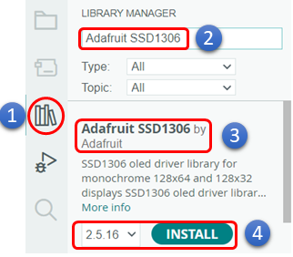
Installing the Adafruit SSD1306 Library
- Open the Arduino IDE. Then click on the Library Manager icon.
- In the search bar, type “Adafruit SSD1306”.
- Look for Adafruit SSD1306 by Adafruit.
- Click the Install button. The Arduino IDE will install the library and add it to your Arduino IDE.
During installation, the IDE will prompt you to install additional libraries required for proper operation. These dependencies typically include the Adafruit GFX Library and the Adafruit BusIO Library.
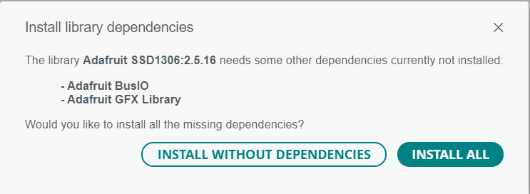
Adafruit GFX Library is the core graphics library that provides functions for drawing shapes, lines, circles, and text, which the SSD1306 library uses.
Adafruit BusIO library is used to handle low-level communication protocols (like I2C and SPI) with the hardware.
When this prompt appears, click “Install All” to ensure that all required components are installed correctly.
Commonly Used Functions of Adafruit SSD1306 Library
1. Adafruit_SSD1306()
This function is a constructor. It creates display objects, configures communication protocol parameters and stores configuration parameters. The display buffer (RAM memory) is allocated when begin() is called, not in the constructor.
Declaration
Adafruit_SSD1306 display(
    SCREEN_WIDTH,
    SCREEN_HEIGHT,
    &Wire,
    RESET_PIN
);
Example for I2C OLED
Adafruit_SSD1306 display(128, 64, &Wire, -1);Parameters
Parameter 1: Display width which is 128 for our OLED
Parameter 2: Display height which is 64 for our OLED
Parameter 3: Communication interface is I2C, hence address of wire object is passed which is automatically accessed once we include <wire.h> in our code
Parameter 4: Reset pin, in our case there is no reset pin provided for this OLED hence passed ‘-1’ as parameter.
Declaration for SPI OLED
Adafruit_SSD1306 display(
    SCREEN_WIDTH,
    SCREEN_HEIGHT,
    &Wire,
    RESET_PIN
);
Example for SPI OLED
#define OLED_DC     9
#define OLED_CS    10
#define OLED_RESET 8

Adafruit_SSD1306 display(128, 64, &SPI, OLED_DC, OLED_RESET, OLED_CS);
Parameters
Parameter 1: Display width which is 128 for our OLED
Parameter 2: Display height which is 64 for our OLED
Parameter 3: Communication interface is SPI, hence address of wire object is passed which is automatically can be accessed once we include <spi.h> in our code
Parameter 4: Data/Command pin, that pin is LOW while sending command over SPI and pin is HIGH while sending data over SPI to the OLED.
Parameter 5: Reset pin, to hard reset the OLED, if there is no reset pin provided for this OLED then ‘-1’ should be passed as param as parameter.
Parameter 6: Chip select pin, it is an active low pin when pin is low OLED is active when this pin is HIGH OLED is inactive.
Return value: It is a constructor and they are automatically called when object is created, they do not have a return value not even void.
2. begin()
This function starts I2C / SPI communication, resets OLED, sends initialization command sequence to SSD1306 driver IC. This function returns true on successful execution and false when it fails.
Declaration for I2C OLED
bool begin(uint8_t vccstate, uint8_t i2caddr);Example for I2C OLED
display.begin(SSD1306_SWITCHCAPVCC, 0x3C);Parameters
Parameter 1: It is OLED power supply mode, it affects contrast & timing commands.
Possible Values
SSD1306_SWITCHCAPVCC: to be used when power supply is 3.3V / 5V and internally this voltage is boosted to initialize OLED, in our case this value is used.
SSD1306_EXTERNALVCC: to be used when externally 7~8 V is used at VCC , usually used in industrial designs.
Parameter 2: Address of OLED display,
Possible Address Values
0x3C: In most cases (90 %), it is 0x3C
0x3D: Alternate address
Declaration for SPI display
bool begin(uint8_t vccstate)Example SPI display
display.begin(SSD1306_SWITCHCAPVCC);Parameters
Parameter 1: It has only one parameter which is same as parameter 1 in I2C mode.
Return Value:
true – Buffer allocated + OLED initialized
false – Failure (usually RAM allocation failure)
3. clearDisplay()
This function clears the software buffer, NOT the OLED display.
Declaration
Void clearDisplay(void);Example
display.clearDisplay();4. display()
This function sends the entire software buffer from MCU RAM to SSD1306 via I2C/SPI. Without calling this, nothing appears on screen.
Declaration
Void display(void);Example
display.display();5. startscrollright()
This function uses SSD1306’s built-in hardware scrolling to start scrolling text from left to right on screen. This function doesn’t update the Software buffer.
Declaration
void startscrollright(uint8_t start, uint8_t stop);Example
display.startscrollright(0x00, 0x07);
Parameters
parameter 1: page number to start the scrolling.
Parameter 2: page number upto which scrolling works.
6. startscrollleft()
This function uses SSD1306’s built-in hardware scrolling to start scrolling text from right to left on screen.
Declaration
void startscrollleft(uint8_t start, uint8_t stop);Example
display.startscrollleft(0x00, 0x07);7. startscrolldiagright()
This function uses SSD1306’s built-in hardware scrolling to start scrolling text from left to right on screen and from bottom to top at the same time.
Declaration
void startscrolldiagright (uint8_t start, uint8_t stop);Example
display. startscrolldiagright (0x00, 0x07);8. startscrolldiagleft ()
This function uses SSD1306’s built-in hardware scrolling to start scrolling text from right to left on screen and from bottom to top at the same time.
Declaration
void startscrolldiagleft (uint8_t start, uint8_t stop);Example
display. startscrolldiagleft (0x00, 0x07);9. stopscroll()
This function disables the SSD1306’s hardware scroll engine, and freezes the display at its current position.
Declaration
void stopscroll(void);Example
display.stopscroll();10. invertDisplay()
This function inverts how bits in display memory are interpreted, without changing the software buffer in MCU RAM.
Normally, bit 1 means pixel ON and bit 0 means pixel OFF. When the display is inverted this is also inverted i.e. bit 1 means pixel Off and bit 0 means pixel ON.
Declaration
void invertDisplay(bool i);Example
display. invertDisplay (true);Parameters
Parameter 1: To enable/disable inversion
True: invert the display
False: normal display
Commonly Used Functions of Adafruit_GFX Library
1. drawPixel()
This function modifies exactly ONE pixel in the software buffer in RAM by setting, clearing, or toggling a single bit; it does NOT update the OLED hardware.
Declaration
void drawPixel(int16_t x, int16_t y, uint16_t color);Example
drawPixel(0,0, SSD1306_WHITE);Parameters
Parameter 1: It is the horizontal pixel position starting from top left corner of screen range from 0 to (width-1). In our case width is 128 pixels hence it would range from 0 to 127.It increases from left to right.
Parameter 2: It is the vertical pixel position starting from top left corner of screen range from 0 to (height-1). In our case height is 64 pixels hence it would range from 0 to 63. It increases from top to bottom.
Parameter 3: It is the color of the pixel. This parameter can have multiple values written below.
Note that for color macro WHITE, BLACK and INVERSE can be used in place of SSD1306_WHITE, SSD1306_BLACK and, SSD1306_INVERSE because in Adafruit_SSD1306.h header file, below macros are also defined:
#define WHITE SSD1306_WHITE // Draw ‘on’ pixels
#define BLACK SSD1306_BLACK // Draw ‘off’ pixels
#define INVERSE SSD1306_INVERSE // Invert pixels
| Value | Meaning | Operation | Usage |
|---|---|---|---|
| SSD1306_WHITE | Pixel ON | Set bit | To turn on the pixel |
| SSD1306_BLACK | Pixel OFF | Clear bit | To turn off a pixel |
| SSD1306_INVERSE | Toggle | XOR bit | To toggle the pixel |
2. setCursor()
This function sets the starting pixel position for the next text character drawn into the software buffer in RAM, it doesn’t draw anything and doesn’t update the display hardware.
Declaration
void setCursor (int16_t x, int16_t y);Example
display.setCursor (0,0);Parameters
Parameter 1: It is the horizontal pixel position.
Parameter 2: It is the vertical pixel position.
3. setTextSize()
This function sets the font of character which will be displayed on OLED. It just says how big or small a character will be displayed on screen. This is software-based font scaling, not hardware zoom.
Declaration
void setTextSize(uint8_t s);Example
display. setTextSize (1);Parameter: It sets the text size can range from 1 to 4. 1 for the smallest size 4 for largest size possible. When the test size is 1 the character takes 1 page length when text size is 4 the character takes 4 page length.
4. setTextColor()
This function sets the colour of the pixel of the display. It updates software buffer not the display directly. It works in two modes setting the foreground colour only and setting foreground and background both.
Declaration
void setTextColor(uint16_t color);
void setTextColor(uint16_t fg, uint16_t bg);
Example
display.setTextColor(SSD1306_WHITE);
display.setTextColor(SSD1306_WHITE , SSD1306_BLACK);
Parameter: There can be two possible colour values:
| Value | Meaning | Operation | Usage |
|---|---|---|---|
| SSD1306_WHITE | Pixel ON | Set bit | To turn on the pixel |
| SSD1306_BLACK | Pixel OFF | Clear bit | To turn off a pixel |
5. setFont()
This function switches the text rendering engine i.e. changes the font type. But whenever we change the font type functions like setTextSize() will not work; they will only work for the default font type.
Declaration
void setFont(const GFXfont *f);Usage Example
display.setFont(&fontName));
display.setFont(&FreeSans9pt7b);
Parameter: Pointer to the structure containing font information. When this parameter is NULL font is set to default.
6. print()
This function prints text or numbers.
Declaration
size_t print(value);   // Default Mode
size_t print(value, BASE);  // Number Formatting mode
Example
display.print(“123”);
display.print(10,HEX);
Parameters for Default Mode
Parameter: The string to be printed.
Parameters for Number Formatting mode
Parameter 1: decimal value
Parameter 2: Base which can be HEX, BIN or OCT
Returns: number of characters printed.
7. write()
This function is the lower-level character output function, it draws a single ASCII character into the display buffer and moves the cursor forward. It can even print special characters using their ASCII values. The print() function internally uses write() function.
Declaration
size_t write(uint8_t c);Example
display.write(0x41);
display.write(‘A’);
Parameter: ASCII value of the character to be printed on OLED display.
Returns: It always returns 1.
Arduino Code to use Basic OLED Functionality
Now let’s start doing cool things with your OLED display.
In this sketch, you’ll discover how to:
- Display clean, simple text
- Flip the screen with inverted text (yes, black becomes white!)
- Show numbers dynamically
- Display numbers in different formats like Decimal and Hex
- Print raw ASCII symbols
- Scroll text left, right, and even diagonally
- Scroll only a selected portion of the screen
/*
Code to display Strings on I2C OLED display as well as SPI OLED display, user has to update the user configuartion based on OLED used
by www.playwithcircuit.com
*/

#include <SPI.h>
#include <Wire.h>
#include <Adafruit_GFX.h>
#include <Adafruit_SSD1306.h>
#include <Fonts/FreeSans12pt7b.h>

// USER CONFIGURATION
#define OLED_TYPE 1  // 0 = I2C, 1 = SPI

#define SCREEN_WIDTH 128
#define SCREEN_HEIGHT 64

// I2C CONFIG
#if OLED_TYPE == 0
#define OLED_ADDR 0x3C
#define OLED_RESET -1  // I2C OLED display doesn't have Exposed reset pin
#endif

// SPI CONFIGURATIONS
#if OLED_TYPE == 1
#define OLED_MOSI 9
#define OLED_CLK 10
#define OLED_DC 11
#define OLED_CS 12
#define OLED_RESET -1  // if SPI OLED display doesn't have Exposed reset pin then its value is -1 else set it to 13 and connect it with pin 13
#endif

// DISPLAY OBJECT
#if OLED_TYPE == 0
Adafruit_SSD1306 display(SCREEN_WIDTH, SCREEN_HEIGHT, &Wire, OLED_RESET);
#else
Adafruit_SSD1306 display(
  SCREEN_WIDTH,
  SCREEN_HEIGHT,
  OLED_MOSI,
  OLED_CLK,
  OLED_DC,
  OLED_RESET,
  OLED_CS);
#endif

// SETUP
void setup() {

  // this serial port is to display error, if occurred during OLED init
  Serial.begin(9600);

  // begin
  #if OLED_TYPE == 0
    if (!display.begin(SSD1306_SWITCHCAPVCC, OLED_ADDR)) {
      Serial.println("SSD1306 init failed");
      while (1)
        ;
    }
  #else
    if (!display.begin(SSD1306_SWITCHCAPVCC)) {

      Serial.println("SSD1306 init failed");
      while (1)
        ;
    }
  #endif
}

void loop() {
  // clear the Display
  display.clearDisplay();

  // draw Pixel on screen
  display.drawPixel(10, 10, WHITE);
  display.drawPixel(20, 10, WHITE);
  display.drawPixel(30, 10, WHITE);

  display.display();
  delay(3000);

  // Display the text on OLED
  display.clearDisplay();
  display.setCursor(0, 20);
  display.setTextSize(1);
  display.setTextColor(WHITE);
  display.print("Hello OLED Display");
  display.display();
  delay(3000);

  // printing hex numbers
  display.clearDisplay();
  display.setCursor(0, 0);
  display.setTextSize(2);
  display.println("Number: ");
  display.println(255);
  display.println("HEX:");
  display.print(255, HEX);
  display.display();
  delay(3000);

  // using write function
  display.clearDisplay();
  display.setCursor(0, 0);
  display.write(3);
  display.write(0x20);
  display.write(4);
  display.write(0x20);
  display.write(5);
  display.write(0x20);
  display.write(6);
  display.write(0x20);
  display.display();
  display.setTextSize(1);
  delay(3000);

  // changing font
  display.clearDisplay();
  display.setFont(&FreeSans12pt7b);
  display.setCursor(0, 30);
  display.setTextColor(WHITE);
  display.print("FreeSans12pt7b");
  display.display();
  delay(3000);

  // Reset to default font
  display.setFont(NULL);

  // inverting the display
  display.clearDisplay();
  display.setCursor(0, 20);
  display.setTextSize(2);
  display.print("Invert Testing");
  display.display();
  delay(3000);

  display.invertDisplay(true);
  delay(3000);
  display.invertDisplay(false);

  // scrolling right
  display.clearDisplay();
  display.setTextSize(1);
  display.setCursor(0, 0);
  display.println("Scroll Right");
  display.display();
  display.startscrollright(0x00, 0x07);
  delay(3000);
  display.stopscroll();

  // scrolling left
  display.clearDisplay();
  display.setCursor(0, 0);
  display.println("Scroll Left");
  display.display();
  display.startscrollleft(0x00, 0x07);
  delay(3000);
  display.stopscroll();

  // scrolling diagonally right
  display.clearDisplay();
  display.setCursor(0, 0);
  display.println("Diag Right");
  display.display();
  display.startscrolldiagright(0x00, 0x07);
  delay(3000);
  display.stopscroll();

  // scrolling diagonally left
  display.clearDisplay();
  display.println("DiagLeft");
  display.display();
  display.startscrolldiagleft(0x00, 0x07);
  delay(3000);
  display.stopscroll();

  // clear the display
  display.clearDisplay();
  display.display();
}
Code Explanation
The sketch begins by including 4 libraries SPI.h, Wire.h, Adafruit_GFX.h, and Adafruit_SSD1306.h. These libraries are required to communicate with the OLED display and render graphics or text on it. SPI library is used when the OLED is connected using SPI protocol. Wire.h library is required when the OLED is connected using I2C protocol. Even if we use only one communication type at runtime, we’ve included both libraries so that the code remains flexible.
Adafruit_GFX.h is the core graphics library that provides fundamental drawing functions. On top of that Adafruit_SSD1306.h is the hardware-specific driver library for the SSD1306 OLED controller.
Finally, we include a custom GFX font file that allows us to use a larger and more visually appealing FreeSans font for better UI design.
#include <SPI.h>
#include <Wire.h>
#include <Adafruit_GFX.h>
#include <Adafruit_SSD1306.h>
#include <Fonts/FreeSans12pt7b.h>
Now we define the basic hardware configuration of the OLED display. The OLED_TYPE macro allows us to select the communication protocol without rewriting the entire program. If we set it to 0, the program compiles for I2C communication. If we set it to 1, it compiles for SPI communication.
The screen width and height define the resolution of the OLED. A 128×64 OLED requires a 1024-byte buffer (because 128 × 64 ÷ 8 = 1024). The library internally allocates this memory. If these values are incorrect, the buffer size won’t match the physical display and unpredictable behavior may occur.
#define OLED_TYPE 1      // 0 = I2C, 1 = SPI
#define SCREEN_WIDTH 128
#define SCREEN_HEIGHT 64
Next, we select I2C Communication by setting OLED_TYPE to 0. The OLED_ADDR defines the I2C address of the display, which is commonly 0x3C. I2C communication uses only two wires: SDA (data) and SCL (clock). The reset pin is set to -1 because most small OLED modules do not expose a dedicated reset pin; they handle reset internally.
The #if directive ensures this configuration is compiled only when required, keeping the program clean and efficient.
#if OLED_TYPE == 0
#define OLED_ADDR 0x3C
#define OLED_RESET -1       // I2C OLED display doesn't have exposed reset pin
#endif
Here we select SPI communication. Unlike I2C, SPI requires multiple control pins. MOSI carries data, CLK synchronizes transmission, DC selects between command and data mode, and CS enables the device.
SPI is generally faster than I2C because it uses dedicated lines for communication. However, it requires more GPIO pins. This configuration gives flexibility depending on project requirements.
  #if OLED_TYPE == 1
  #define OLED_MOSI  9
  #define OLED_CLK   10
  #define OLED_DC    11
  #define OLED_CS    12
  #define OLED_RESET -1                   // if SPI OLED display doesn't have Exposed reset pin then its value is -1 else set it to 13 and connect in hardware
#endif
Here we create the display object differently depending on the communication type. For I2C, we pass the Wire library reference because I2C uses a shared bus system. For SPI, we pass all required control pins.
The rest of the program does not care whether the display is I2C or SPI. All display commands remain identical.
#if OLED_TYPE == 0
  Adafruit_SSD1306 display(SCREEN_WIDTH, SCREEN_HEIGHT, &Wire, OLED_RESET);
#else
  Adafruit_SSD1306 display(
    SCREEN_WIDTH,
    SCREEN_HEIGHT,
    OLED_MOSI,
    OLED_CLK,
    OLED_DC,
    OLED_RESET,
    OLED_CS
  );
#endif
In the setup function, the display.begin() function initializes the OLED driver. The condition checks whether initialization was successful. If not, the program prints an error message and enters an infinite loop.
void setup() {
  Serial.begin(9600);
#if OLED_TYPE == 0
  if (!display.begin(SSD1306_SWITCHCAPVCC, OLED_ADDR)) {
#else
  if (!display.begin(SSD1306_SWITCHCAPVCC)) {
#endif
    Serial.println("SSD1306 init failed");
    while (1);
  }
}
In the loop function, first we clear the display using display.clearDisplay() function.
Next, we use the drawPixel function which turns ON a specific pixel at coordinate (x, y). OLED displays are monochrome, meaning each pixel can either be ON (WHITE) or OFF (BLACK).
The most important function here is display.display(). Until this function is called, nothing appears on the screen because all changes are only in RAM. This prevents flickering and allows smooth graphic updates.
void loop() {
  // clear the Display
  display.clearDisplay();
  // draw Pixel on screen
  display.drawPixel(10, 10, WHITE);
  display.drawPixel(20, 10, WHITE);
  display.drawPixel(30, 10, WHITE);
  display.display();
  delay(3000);
Next, we display a simple message on the OLED screen.
We begin with display.clearDisplay(), which clears the internal display buffer. Since the SSD1306 uses a RAM buffer, old content must be erased before drawing something new.
Next, we set the starting position of the text using display.setCursor(0, 20). The first value (0) represents the horizontal position from the left edge, and the second value (20) represents the vertical position from the top. The coordinate system starts at (0, 0) in the top-left corner.
Next, we set the font size using display.setTextSize(). The default size is 1. Using larger numbers increases the text size.
Next, we define the color of the text using display.setTextColor(). Since the OLED background is black, WHITE turns the text pixels ON, making them visible.
Next, we write the message “Hello OLED Display” into the display buffer using display.print(). At this stage, the text is stored in memory but not yet visible.
Next, we use display.display() function to update the screen and display the text.
Finally, delay(3000) keeps the message on screen for three seconds before the program continues.
  display.clearDisplay();
  display.setCursor(0, 20);
  display.setTextSize(1);
  display.setTextColor(WHITE);
  display.print("Hello OLED Display");
  display.display();
  delay(3000);
Displaying ASCII Symbols Using write()
This code displays special ASCII characters directly on the OLED screen.
It starts with display.clearDisplay(), which clears the internal buffer.
display.setCursor() positions the cursor at the top-left corner of the screen. All characters written afterward will begin from this position and move horizontally as they are printed.
Here we use display.write() function to send raw byte values directly to the display. These numbers correspond to ASCII character codes. For example, values like 3, 4, 5, and 6 represent specific symbols defined in the display’s character table.
Between each symbol display.write(0x20) is used. The value 0x20 is the hexadecimal ASCII code for a space character. This creates spacing between the symbols.
After writing all characters into the buffer, display.display() makes the symbols visible on screen.
display.setTextSize(1) ensures the font size is set to the default (in case it was changed earlier in the program). Finally, delay(3000) keeps the symbols visible for three seconds.
  display.clearDisplay();
  display.setCursor(0, 0);
  display.write(3);
  display.write(0x20);
  display.write(4);
  display.write(0x20);
  display.write(5);
  display.write(0x20);
  display.write(6);
  display.write(0x20);
  display.display();
  display.setTextSize(1);
  delay(3000);
Using a Custom GFX Font
This code shows how to use a custom font instead of the default built-in font.
First, we change the active font to FreeSans 12pt, which is part of the Adafruit GFX font collection using display.setFont. Unlike the default 5×7 pixel font, GFX fonts are proportional and larger, giving a more professional appearance.
Next, we set the starting position of the text using display.setCursor(). With GFX fonts, the cursor position refers to the baseline of the text rather than the top-left corner of a character box. That’s why a Y value like 30 is chosen — it ensures the full character height appears within the screen.
Next, we define the text color using display.setTextColor() as WHITE.
Next, we write the text into the display buffer using display.print(). As always, display.display() make the text visible on screen.
After a 3-second delay, we reset the font back to the default built-in font.
  display.clearDisplay();
  display.setFont(&FreeSans12pt7b);
  display.setCursor(0, 30);
  display.setTextColor(WHITE);
  display.print("FreeSans12pt7b");
  display.display();
  delay(3000);
  // Reset to default font
  display.setFont(NULL);
Inverting the Display
This example shows the invertDisplay() function, which flips the entire screen’s pixel output.
First we display the enlarged text normally using setTextSize(2). invertDisplay(true) activates hardware-level inversion. This means every pixel currently ON becomes OFF, and every OFF pixel becomes ON — turning black areas white and white areas black.
After three seconds, invertDisplay(false) restores the normal display mode.
 display.clearDisplay();
  display.setCursor(0, 20);
  display.setTextSize(2);
  display.print("Invert Testing");
  display.display();
  delay(3000);

  display.invertDisplay(true);
  delay(3000);
  display.invertDisplay(false);
Scrolling Right
This code displays a message and then makes it scroll to the right.
We start by clearing the screen and keeping the font at its normal size. The cursor is placed at the top-left corner.
println() writes the text “Scroll Right” into the display memory. The content becomes visible after calling display.display().
Now comes the interesting part: startscrollright(0x00, 0x07); activates hardware scrolling. The values 0x00 and 0x07 represent the start and end pages of the display. Since a 64-pixel OLED has 8 pages (numbered 0 to 7), this command scrolls the entire screen.
The text moves smoothly to the right for three seconds. After that, stopscroll() stops the motion and freezes the display at its current position.
  display.clearDisplay();
  display.setTextSize(1);
  display.setCursor(0, 0);
  display.println("Scroll Right");
  display.display();
  display.startscrollright(0x00, 0x07);
  delay(3000);
  display.stopscroll();
Scrolling Left
Here, we simply change the scroll direction. We use startscrollleft(), which moves the display content toward the left. The scrolling logic remains the same — only the direction changes.
  display.clearDisplay();
  display.setCursor(0, 0);
  display.println("Scroll Left");
  display.display();
  display.startscrollleft(0x00, 0x07);
  delay(3000);
  display.stopscroll();
Scrolling Diagonally Right
Here, we scroll the text diagonally. Instead of horizontal movement, startscrolldiagright() shifts the content both horizontally and vertically, creating a diagonal motion toward the right.
display.clearDisplay();
  display.setCursor(0, 0);
  display.println("Diag Right");
  display.display();
  display.startscrolldiagright(0x00, 0x07);
  delay(3000);
  display.stopscroll();
Scrolling Diagonally Left
Here, we simply change the diagonal direction. By using startscrolldiagleft(), the text now moves diagonally towards the left instead of the right.
display.clearDisplay();
  display.println("DiagLeft");
  display.display();
  display.startscrolldiagleft(0x00, 0x07);
  delay(3000);
  display.stopscroll();

  // Final clear
  display.clearDisplay();
  display.display();
}
Output
Drawing Shapes on OLED Display
For drawing shapes on OLED display we will use some functions of Adafruit_GFX library.
1. drawLine()
This function draws a straight line between two points by plotting multiple pixels in the software buffer in RAM, it doesn’t draw anything and doesn’t update the display hardware.
Declaration
void drawLine(int16_t x0, int16_t y0, int16_t x1, int16_t y1, uint16_t color);Example
display. drawLine (0, 0, 50, 50, WHITE);Parameters
Parameter 1: It is the horizontal position of first pixel of line it ranges from 0 – 127.
Parameter 2: It is the vertical position of first pixel of line it ranges from 0 – 63.
Parameter 3: It is the horizontal position of last pixel of line it ranges from 0 – 127.
Parameter 4: It is the vertical position of last pixel of line it ranges from 0 – 63.
Parameter 5: It can be WHITE, BLACK, or INVERSE.
2. drawRect()
This function draws a hollow rectangle using 4 lines, in the software buffer in RAM, it doesn’t draw anything and doesn’t update the display hardware.
Declaration
void drawRect(int16_t x, int16_t y, int16_t w, int16_t h, uint16_t color);Example
display. drawRect (0,0);Parameters
Parameter 1: It is the horizontal position of top left pixel of rectangle it ranges from 0–127.
Parameter 2: It is the vertical position of top left pixel of rectangle, it ranges from 0–63.
Parameter 3: It is the width of rectangle in pixel.
Parameter 4: It is the height of rectangle in pixel.
Parameter 5: It can be WHITE, BLACK, INVERSE.
3. fillRect()
This function draws a filled rectangle by drawing multiple horizontal lines, in the software buffer in RAM, it doesn’t draw anything and doesn’t update the display hardware. The parameters, usage and return value are the same as drawRect() function.
4. drawCircle()
This function draws a hollow circle, in the software buffer in RAM, it doesn’t draw anything and doesn’t update the display hardware.
Declaration
void drawCircle(int16_t x0, int16_t y0, int16_t r, uint16_t color);Example
display.drawCircle(64, 32, 20, WHITE);Parameters
Parameter 1: It is the horizontal position of centre of circle it ranges from 0–127.
Parameter 2: It is the vertical position of centre of circle it ranges from 0–63.
Parameter 3: It is the radius of circle in pixel.
Parameter 4: It can be WHITE, BLACK, or INVERSE.
5. fillCircle()
This function draws a filled circle, in the software buffer in RAM, it doesn’t draw anything and doesn’t update the display hardware. The parameters, usage and return value is same as drawCircle() function.
6. drawTriangle()
This function draws a hollow triangle in the software buffer in RAM, it doesn’t draw anything and doesn’t update the display hardware.
Declaration
void drawTriangle(int16_t x0, int16_t y0, int16_t x1, int16_t y1, int16_t x2, int16_t y2, uint16_t color);Example
display.drawTriangle(20, 10, 100, 10, 60, 50, WHITE);Parameters
Parameter 1: It is the horizontal position of first vertex of triangle it ranges from 0 – 127.
Parameter 2: It is the vertical position of first vertex of triangle it ranges from 0 – 63.
Parameter 3: It is the horizontal position of second vertex of triangle it ranges from 0 – 127.
Parameter 4: It is the vertical position of second vertex of triangle it ranges from 0 – 63.
Parameter 5: It is the horizontal position of third vertex of triangle it ranges from 0 – 127.
Parameter 6: It is the vertical position of third vertex of triangle it ranges from 0 – 63.
Parameter 7: It can be WHITE, BLACK, INVERSE.
7. fillTriangle()
This function draws a filled triangle, in the software buffer in RAM, it doesn’t draw anything and doesn’t update the display hardware. The parameters, usage and return value is same as drawTriangle() function.
8. drawRoundRect()
This function draws a hollow rectangle with rounded corners, in the software buffer in RAM, it doesn’t draw anything and doesn’t update the display hardware.
Declaration
void drawRoundRect(int16_t x, int16_t y, int16_t w, int16_t h, int16_t r, uint16_t color);Example
display.drawRoundRect(10, 10, 100, 40, 10, WHITE);Parameters
Parameter 1: It is the horizontal position of top left pixel of rectangle it ranges from 0–127.
Parameter 2: It is the vertical position of top left pixel of rectangle it ranges from 0–63.
Parameter 3: It is the width of rectangle in pixel.
Parameter 4: It is the height of rectangle in pixel.
Parameter 5: Radius of rounded corners.
Parameter 6: It can be WHITE, BLACK or INVERSE.
9. fillRoundRect()
This function draws a filled rectangle with rounded corners, in the software buffer in RAM, it doesn’t draw anything and doesn’t update the display hardware. The parameters, usage and return value is same as drawRoundRect() function.
Arduino Code to Draw Shapes on OLED
This Arduino sketch shows how to draw simple shapes like rectangle, circle, and triangle on the OLED display.
/*
Code to display shapes on I2C OLED display as well as SPI OLED display, user has to update the user configuration based on OLED used
by www.playwithcircuit.com
*/

#include <SPI.h>
#include <Wire.h>
#include <Adafruit_GFX.h>
#include <Adafruit_SSD1306.h>
#include <Fonts/FreeSans12pt7b.h>

// USER CONFIGURATION
#define OLED_TYPE 0  // 0 = I2C, 1 = SPI

#define SCREEN_WIDTH 128
#define SCREEN_HEIGHT 64

// I2C CONFIG
#if OLED_TYPE == 0
#define OLED_ADDR 0x3C
#define OLED_RESET -1  // I2C OLED display doesn't have Exposed reset pin
#endif

// SPI CONFIGURATIONS
#if OLED_TYPE == 1
#define OLED_MOSI 9
#define OLED_CLK 10
#define OLED_DC 11
#define OLED_CS 12
#define OLED_RESET -1  // if SPI OLED display doesn't have Exposed reset pin the its value is -1 else set it to 13 and connect in hardware
#endif

// DISPLAY OBJECT
#if OLED_TYPE == 0
Adafruit_SSD1306 display(SCREEN_WIDTH, SCREEN_HEIGHT, &Wire, OLED_RESET);
#else
Adafruit_SSD1306 display(
  SCREEN_WIDTH,
  SCREEN_HEIGHT,
  OLED_MOSI,
  OLED_CLK,
  OLED_DC,
  OLED_RESET,
  OLED_CS);
#endif

// this function display the name of function being used
void showTitle(const char *title) {
  display.clearDisplay();
  display.setTextSize(1);
  display.setTextColor(WHITE);
  display.setCursor(0, 25);
  display.println(title);
  display.display();
  delay(1500);
}

// SETUP
void setup() {
  // this serial port is to display error, if occurred during OLED init
  Serial.begin(9600);

  // begin
  #if OLED_TYPE == 0
    if (!display.begin(SSD1306_SWITCHCAPVCC, OLED_ADDR)) {
      Serial.println("SSD1306 init failed");
      while (1)
        ;
    }
  #else
    if (!display.begin(SSD1306_SWITCHCAPVCC)) {
      Serial.println("SSD1306 init failed");
      while (1)
        ;
    }
  #endif
}

void loop() {
  // Drawing a line
  showTitle("drawLine()");
  display.clearDisplay();
  display.drawLine(0, 0, 127, 63, WHITE);
  display.display();
  delay(2000);

  // draw rectangle
  showTitle("drawRect()");
  display.clearDisplay();
  display.drawRect(20, 10, 80, 40, WHITE);
  display.display();
  delay(2000);

  // draw filled rectangle
  showTitle("fillRect()");
  display.clearDisplay();
  display.fillRect(20, 10, 80, 40, WHITE);
  display.display();
  delay(2000);

  // draw circle
  showTitle("drawCircle()");
  display.clearDisplay();
  display.drawCircle(64, 32, 20, WHITE);
  display.display();
  delay(2000);

  // draw filled circle
  showTitle("fillCircle()");
  display.clearDisplay();
  display.fillCircle(64, 32, 20, WHITE);
  display.display();
  delay(2000);

  // draw triangle
  showTitle("drawTriangle()");
  display.clearDisplay();
  display.drawTriangle(20, 10, 100, 10, 60, 50, WHITE);
  display.display();
  delay(2000);

  // draw filled triangle
  showTitle("fillTriangle()");
  display.clearDisplay();
  display.fillTriangle(20, 10, 100, 10, 60, 50, WHITE);
  display.display();
  delay(2000);

  // draw rounded rectangle
  showTitle("drawRoundRect()");
  display.clearDisplay();
  display.drawRoundRect(20, 10, 80, 40, 10, WHITE);
  display.display();
  delay(2000);

  // draw filled rounded rectangle
  showTitle("fillRoundRect()");
  display.clearDisplay();
  display.fillRoundRect(20, 10, 80, 40, 10, WHITE);
  display.display();
  delay(2000);
}
Output
How to display Images on OLED display
Displaying images on an OLED is slightly different from displaying text or shapes, because the OLED cannot directly understand common image formats like JPG or PNG. Instead, it works at the pixel level, where each pixel is either ON or OFF. Because of this, the image must first be converted into a byte array, which is simply a collection of numbers representing the pixel data. Each bit in this array corresponds to a pixel on the screen, allowing the OLED to recreate the image accurately. To make this process simple we will use a tool Image2CPP that can convert your image into array.
How to Use Image2CPP Tool to Display Images on OLED
Step 1Selecting a Suitable Image
The first step is to choose an image that works well with a monochrome display. Since most OLEDs are black and white, colorful or highly detailed images may lose clarity after conversion. It is best to use simple images such as logos, icons, or high-contrast graphics.
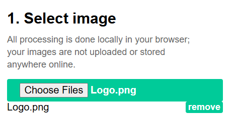
Step 2Uploading Image to Conversion Tool
Now open the Image2CPP tool and upload your image using the Select Image option. Here we are using our logo.
Step 3Adjusting Image Settings for Clarity
After uploading the image, match the image resolution with your OLED display. Most commonly used OLED displays have a resolution of 128×64 pixels. If the image size does not match this resolution, it may appear distorted or partially cut off. You can also use option “scale to fit” to resize the image properly.
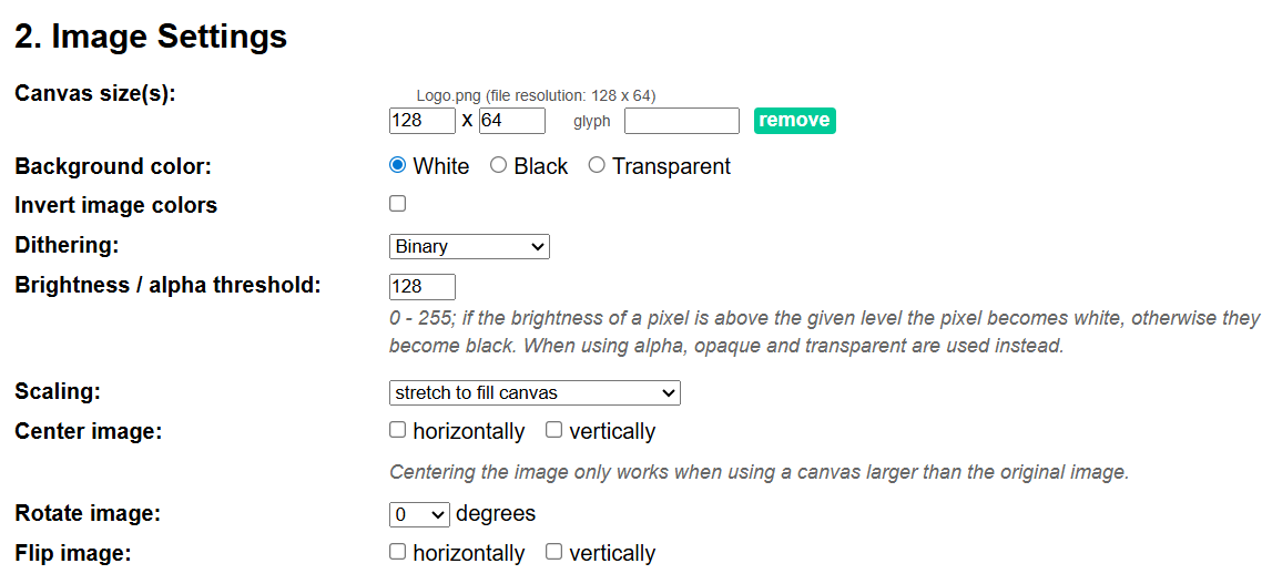
You can also adjust the other image settings to get the best possible output. You can increase or decrease the brightness of image using brightness threshold. You can also use options like inversion to flip colors if needed.
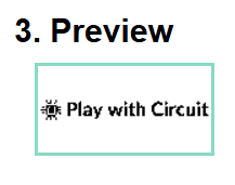
The preview section shows exactly how your image will appear on the OLED. As you adjust settings, the preview updates in real time.
Step 5Generating the Byte Array Code
The next step is to generate the code. Select: Code Output format → Arduino code. Then click “Generate Code” button, the tool converts the image into a byte array.
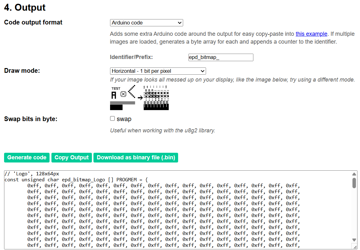
Step 6Adding the Image Array to Arduino Code
Next, copy the byte array and paste it into your Arduino program.
Step 7Displaying the Image Using drawBitmap()
The final step is to display the image on the OLED screen. This is done using the drawBitmap() function from the Adafruit GFX library. This step completes the entire process, turning the numerical array back into a visible image.
drawBitmap() function of Adafruit_GFX library
This function draws image on OLED display, pixel by pixel in the software buffer in RAM, it doesn’t draw anything and doesn’t update the display hardware.
Declaration
void drawBitmap(int16_t x, int16_t y, const uint8_t *bitmap, int16_t w, int16_t h, uint16_t color);Example
display.drawBitmap(40, 20, logo, 8, 8, WHITE);Parameters
Parameter 1: It is the horizontal position of first pixel of image it ranges from 0–127.
Parameter 2: It is the vertical position of first pixel of image it ranges from 0–63.
Parameter 3: It is an array of bytes, each byte contains information of 8 pixels and it should be stored in PROGMEM (Flash).
Parameter 4: Width of image in pixel.
Parameter 5: Height of image in pixel.
Parameter 6: It can be WHITE, BLACK or INVERSE.
Arduino Code to Display an Image on OLED
This code shows how to display an image on I2C as well as SPI OLED displays. Simply update the user configuration section according to the OLED type you are using.
/*
Code to display Image on I2C OLED display as well as SPI OLED display, user has to update the user configuration based on OLED used
by www.playwithcircuit.com
*/

#include <SPI.h>
#include <Wire.h>
#include <Adafruit_GFX.h>
#include <Adafruit_SSD1306.h>
#include <Fonts/FreeSans12pt7b.h>

// USER CONFIGURATION
#define OLED_TYPE 1  // 0 = I2C, 1 = SPI

#define SCREEN_WIDTH 128
#define SCREEN_HEIGHT 64

// I2C CONFIG
#if OLED_TYPE == 0
#define OLED_ADDR 0x3C
#define OLED_RESET -1  // I2C OLED display doesn't have Exposed reset pin
#endif

// SPI CONFIGURATIONS
#if OLED_TYPE == 1
#define OLED_MOSI 9
#define OLED_CLK 10
#define OLED_DC 11
#define OLED_CS 12
#define OLED_RESET -1  // if SPI OLED display doesn't have Exposed reset pin the its value is -1 else set it to 13 and connect in hardware
#endif

// DISPLAY OBJECT
#if OLED_TYPE == 0
Adafruit_SSD1306 display(SCREEN_WIDTH, SCREEN_HEIGHT, &Wire, OLED_RESET);
#else
Adafruit_SSD1306 display(
  SCREEN_WIDTH,
  SCREEN_HEIGHT,
  OLED_MOSI,
  OLED_CLK,
  OLED_DC,
  OLED_RESET,
  OLED_CS);
#endif

const unsigned char logo128x64[] PROGMEM = {
        0xff, 0xff, 0xff, 0xff, 0xff, 0xff, 0xff, 0xff, 0xff, 0xff, 0xff, 0xff, 0xff, 0xff, 0xff, 0xff,
        0xff, 0xff, 0xff, 0xff, 0xff, 0xff, 0xff, 0xff, 0xff, 0xff, 0xff, 0xff, 0xff, 0xff, 0xff, 0xff,
        0xff, 0xff, 0xff, 0xff, 0xff, 0xff, 0xff, 0xff, 0xff, 0xff, 0xff, 0xff, 0xff, 0xff, 0xff, 0xff,
        0xff, 0xff, 0xff, 0xff, 0xff, 0xff, 0xff, 0xff, 0xff, 0xff, 0xff, 0xff, 0xff, 0xff, 0xff, 0xff,
        0xff, 0xff, 0xff, 0xff, 0xff, 0xff, 0xff, 0xff, 0xff, 0xff, 0xff, 0xff, 0xff, 0xff, 0xff, 0xff,
        0xff, 0xff, 0xff, 0xff, 0xff, 0xff, 0xff, 0xff, 0xff, 0xff, 0xff, 0xff, 0xff, 0xff, 0xff, 0xff,
        0xff, 0xff, 0xff, 0xff, 0xff, 0xff, 0xff, 0xff, 0xff, 0xff, 0xff, 0xff, 0xff, 0xff, 0xff, 0xff,
        0xff, 0xff, 0xff, 0xff, 0xff, 0xff, 0xff, 0xff, 0xff, 0xff, 0xff, 0xff, 0xff, 0xff, 0xff, 0xff,
        0xff, 0xff, 0xff, 0xff, 0xff, 0xff, 0xff, 0xff, 0xff, 0xff, 0xff, 0xff, 0xff, 0xff, 0xff, 0xff,
        0xff, 0xff, 0xff, 0xff, 0xff, 0xff, 0xff, 0xff, 0xff, 0xff, 0xff, 0xff, 0xff, 0xff, 0xff, 0xff,
        0xff, 0xff, 0xff, 0xff, 0xff, 0xff, 0xff, 0xff, 0xff, 0xff, 0xff, 0xff, 0xff, 0xff, 0xff, 0xff,
        0xff, 0xff, 0xff, 0xff, 0xff, 0xff, 0xff, 0xff, 0xff, 0xff, 0xff, 0xff, 0xff, 0xff, 0xff, 0xff,
        0xff, 0xff, 0xff, 0xff, 0xff, 0xff, 0xff, 0xff, 0xff, 0xff, 0xff, 0xff, 0xff, 0xff, 0xff, 0xff,
        0xff, 0xff, 0xff, 0xff, 0xff, 0xff, 0xff, 0xff, 0xff, 0xff, 0xff, 0xff, 0xff, 0xff, 0xff, 0xff,
        0xff, 0xff, 0xff, 0xff, 0xff, 0xff, 0xff, 0xff, 0xff, 0xff, 0xff, 0xff, 0xff, 0xff, 0xff, 0xff,
        0xff, 0xff, 0xff, 0xff, 0xff, 0xff, 0xff, 0xff, 0xff, 0xff, 0xff, 0xff, 0xff, 0xff, 0xff, 0xff,
        0xff, 0xff, 0xff, 0xff, 0xff, 0xff, 0xff, 0xff, 0xff, 0xff, 0xff, 0xff, 0xff, 0xff, 0xff, 0xff,
        0xff, 0xff, 0xff, 0xff, 0xff, 0xff, 0xff, 0xff, 0xff, 0xff, 0xff, 0xff, 0xff, 0xff, 0xff, 0xff,
        0xff, 0xff, 0xff, 0xff, 0xff, 0xff, 0xff, 0xff, 0xff, 0xff, 0xff, 0xff, 0xff, 0xff, 0xff, 0xff,
        0xff, 0xff, 0xff, 0xff, 0xff, 0xff, 0xff, 0xff, 0xff, 0xff, 0xff, 0xff, 0xff, 0xff, 0xff, 0xff,
        0xff, 0xff, 0xff, 0xff, 0xff, 0xff, 0xff, 0xff, 0xff, 0xff, 0xff, 0xff, 0xff, 0xff, 0xff, 0xff,
        0xff, 0xff, 0xff, 0xff, 0xff, 0xff, 0xff, 0xff, 0xff, 0xff, 0xff, 0xff, 0xff, 0xff, 0xff, 0xff,
        0xff, 0xff, 0xff, 0xff, 0xff, 0xff, 0xff, 0xff, 0xff, 0xff, 0xff, 0xff, 0xff, 0xff, 0xff, 0xff,
        0xfb, 0xdf, 0xff, 0xff, 0xff, 0xff, 0xff, 0xff, 0xff, 0xff, 0xff, 0xff, 0xff, 0xff, 0xff, 0xff,
        0xf9, 0xce, 0x7f, 0xff, 0xff, 0xff, 0xff, 0xff, 0xff, 0xff, 0xff, 0xff, 0xff, 0xff, 0xff, 0xff,
        0xf9, 0xde, 0xff, 0xff, 0xff, 0xff, 0xff, 0xff, 0xff, 0xff, 0xff, 0xff, 0xff, 0xff, 0xff, 0xff,
        0xfc, 0xd4, 0xff, 0xff, 0xff, 0xff, 0xff, 0xff, 0xff, 0xff, 0xff, 0xff, 0xff, 0xff, 0xff, 0xff,
        0xff, 0xfd, 0xff, 0x01, 0x8f, 0xff, 0xff, 0xff, 0xe7, 0xf9, 0xff, 0x83, 0x3f, 0xff, 0xfe, 0x7f,
        0xfc, 0x00, 0xff, 0x00, 0x8f, 0xff, 0xff, 0xff, 0xe7, 0x71, 0xff, 0x01, 0x3f, 0xff, 0xfe, 0x67,
        0xb8, 0x7e, 0x67, 0x1c, 0x8f, 0xff, 0xff, 0xff, 0xfe, 0x71, 0xfe, 0x3f, 0xff, 0xff, 0xff, 0xe7,
        0x88, 0xc2, 0x47, 0x1c, 0x8c, 0x33, 0xde, 0x77, 0xa6, 0x10, 0x3e, 0x7f, 0x74, 0xc6, 0x76, 0xc3,
        0xe9, 0x02, 0x5f, 0x1c, 0x88, 0x13, 0x9e, 0x63, 0x24, 0x10, 0x1e, 0x7f, 0x20, 0x82, 0x66, 0x41,
        0xf9, 0x02, 0x7f, 0x00, 0x8f, 0x91, 0x9e, 0x63, 0x26, 0x31, 0x9e, 0x7f, 0x23, 0x9e, 0x66, 0x67,
        0x89, 0x02, 0x07, 0x01, 0x8e, 0x19, 0x1f, 0x22, 0x66, 0x71, 0x9e, 0x7f, 0x23, 0x3e, 0x66, 0x67,
        0xf9, 0x02, 0x7f, 0x1f, 0x88, 0x18, 0x3f, 0x08, 0x66, 0x71, 0x9e, 0x7f, 0x27, 0x3e, 0x66, 0x67,
        0xe9, 0x02, 0x5f, 0x1f, 0x89, 0x9c, 0x3f, 0x08, 0x66, 0x31, 0x9e, 0x3f, 0x27, 0x1e, 0x66, 0x67,
        0xb9, 0x02, 0x57, 0x1f, 0x88, 0x1c, 0x7f, 0x88, 0xe6, 0x11, 0x9f, 0x01, 0x27, 0x82, 0x06, 0x63,
        0x89, 0xfe, 0x67, 0x9f, 0xd8, 0x1c, 0x7f, 0x9c, 0xe7, 0x1b, 0x9f, 0x83, 0x27, 0xc3, 0x06, 0x61,
        0xfc, 0x00, 0xff, 0xff, 0xff, 0xfc, 0x7f, 0xff, 0xff, 0xff, 0xff, 0xff, 0xff, 0xff, 0xff, 0xff,
        0xff, 0xff, 0xff, 0xff, 0xff, 0xf8, 0xff, 0xff, 0xff, 0xff, 0xff, 0xff, 0xff, 0xff, 0xff, 0xff,
        0xfc, 0x54, 0xff, 0xff, 0xff, 0xf9, 0xff, 0xff, 0xff, 0xff, 0xff, 0xff, 0xff, 0xff, 0xff, 0xff,
        0xfd, 0xde, 0xff, 0xff, 0xff, 0xff, 0xff, 0xff, 0xff, 0xff, 0xff, 0xff, 0xff, 0xff, 0xff, 0xff,
        0xf9, 0xce, 0x7f, 0xff, 0xff, 0xff, 0xff, 0xff, 0xff, 0xff, 0xff, 0xff, 0xff, 0xff, 0xff, 0xff,
        0xff, 0xff, 0xff, 0xff, 0xff, 0xff, 0xff, 0xff, 0xff, 0xff, 0xff, 0xff, 0xff, 0xff, 0xff, 0xff,
        0xff, 0xff, 0xff, 0xff, 0xff, 0xff, 0xff, 0xff, 0xff, 0xff, 0xff, 0xff, 0xff, 0xff, 0xff, 0xff,
        0xff, 0xff, 0xff, 0xff, 0xff, 0xff, 0xff, 0xff, 0xff, 0xff, 0xff, 0xff, 0xff, 0xff, 0xff, 0xff,
        0xff, 0xff, 0xff, 0xff, 0xff, 0xff, 0xff, 0xff, 0xff, 0xff, 0xff, 0xff, 0xff, 0xff, 0xff, 0xff,
        0xff, 0xff, 0xff, 0xff, 0xff, 0xff, 0xff, 0xff, 0xff, 0xff, 0xff, 0xff, 0xff, 0xff, 0xff, 0xff,
        0xff, 0xff, 0xff, 0xff, 0xff, 0xff, 0xff, 0xff, 0xff, 0xff, 0xff, 0xff, 0xff, 0xff, 0xff, 0xff,
        0xff, 0xff, 0xff, 0xff, 0xff, 0xff, 0xff, 0xff, 0xff, 0xff, 0xff, 0xff, 0xff, 0xff, 0xff, 0xff,
        0xff, 0xff, 0xff, 0xff, 0xff, 0xff, 0xff, 0xff, 0xff, 0xff, 0xff, 0xff, 0xff, 0xff, 0xff, 0xff,
        0xff, 0xff, 0xff, 0xff, 0xff, 0xff, 0xff, 0xff, 0xff, 0xff, 0xff, 0xff, 0xff, 0xff, 0xff, 0xff,
        0xff, 0xff, 0xff, 0xff, 0xff, 0xff, 0xff, 0xff, 0xff, 0xff, 0xff, 0xff, 0xff, 0xff, 0xff, 0xff,
        0xff, 0xff, 0xff, 0xff, 0xff, 0xff, 0xff, 0xff, 0xff, 0xff, 0xff, 0xff, 0xff, 0xff, 0xff, 0xff,
        0xff, 0xff, 0xff, 0xff, 0xff, 0xff, 0xff, 0xff, 0xff, 0xff, 0xff, 0xff, 0xff, 0xff, 0xff, 0xff,
        0xff, 0xff, 0xff, 0xff, 0xff, 0xff, 0xff, 0xff, 0xff, 0xff, 0xff, 0xff, 0xff, 0xff, 0xff, 0xff,
        0xff, 0xff, 0xff, 0xff, 0xff, 0xff, 0xff, 0xff, 0xff, 0xff, 0xff, 0xff, 0xff, 0xff, 0xff, 0xff,
        0xff, 0xff, 0xff, 0xff, 0xff, 0xff, 0xff, 0xff, 0xff, 0xff, 0xff, 0xff, 0xff, 0xff, 0xff, 0xff,
        0xff, 0xff, 0xff, 0xff, 0xff, 0xff, 0xff, 0xff, 0xff, 0xff, 0xff, 0xff, 0xff, 0xff, 0xff, 0xff,
        0xff, 0xff, 0xff, 0xff, 0xff, 0xff, 0xff, 0xff, 0xff, 0xff, 0xff, 0xff, 0xff, 0xff, 0xff, 0xff,
        0xff, 0xff, 0xff, 0xff, 0xff, 0xff, 0xff, 0xff, 0xff, 0xff, 0xff, 0xff, 0xff, 0xff, 0xff, 0xff,
        0xff, 0xff, 0xff, 0xff, 0xff, 0xff, 0xff, 0xff, 0xff, 0xff, 0xff, 0xff, 0xff, 0xff, 0xff, 0xff,
        0xff, 0xff, 0xff, 0xff, 0xff, 0xff, 0xff, 0xff, 0xff, 0xff, 0xff, 0xff, 0xff, 0xff, 0xff, 0xff,
        0xff, 0xff, 0xff, 0xff, 0xff, 0xff, 0xff, 0xff, 0xff, 0xff, 0xff, 0xff, 0xff, 0xff, 0xff, 0xff
};

// SETUP
void setup() {

  // this serial port is to display error, if occurred during OLED init
  Serial.begin(9600);

  // begin
  #if OLED_TYPE == 0
    if (!display.begin(SSD1306_SWITCHCAPVCC, OLED_ADDR)) {
      Serial.println("SSD1306 init failed");
      while (1)
        ;
    }
  #else
    if (!display.begin(SSD1306_SWITCHCAPVCC)) {

      Serial.println("SSD1306 init failed");
      while (1)
        ;
    }
  #endif

  // Clear the buffer.
  display.clearDisplay();

  // Display bitmap
  display.drawBitmap(0, 0, logo128x64, 128, 64, WHITE);
  display.display();
}

void loop() {
}
Output
FAQ’S
Why is OLED display not working with Arduino?
An OLED display may not work due to some common issues such as incorrect wiring connections or using the wrong I2C address (typically 0x3C or 0x3D). Another frequent mistake is forgetting to call the display.display() function, which is necessary to transfer data from the microcontroller’s memory to the screen. Power supply problems, such as unstable voltage or loose connections, can also prevent the display from functioning properly.
What is the difference between I2C and SPI OLED displays?
I2C requires only two data lines (SDA and SCL), making it simpler and more suitable for beginners or projects with limited GPIO pins. However, it is relatively slower. SPI, on the other hand, uses multiple dedicated lines such as MOSI, CLK, CS, and DC, allowing faster data transfer and better performance, especially for graphics-heavy applications.
Why is my OLED display flickering?
Flickering in OLED displays typically occurs when the display is refreshed too frequently or when the buffer is not managed correctly. Continuously calling the display.display() function in a tight loop without proper timing can cause visible flicker. Similarly, not clearing the buffer using display.clearDisplay() before drawing new content can lead to inconsistent visuals. Optimizing refresh rates and managing buffer updates helps eliminate flickering issues.
Why are graphics not displaying correctly on my OLED?
Graphics issues often occur when the resolution defined in the code does not match the actual OLED display. For example, using settings for a 128×64 display on a 128×32 screen can lead to distorted or partially visible graphics. Additionally, incorrect bitmap dimensions or improper scaling can cause display errors. Ensuring that the screen width, height, and image dimensions are correctly configured resolves most graphical issues.
What is the difference between OLED and LCD displays?
The primary difference between OLED and LCD displays lies in how they produce light. OLED displays use pixels and each pixel generates its own light, resulting in high contrast and better viewing angles. In contrast, LCD displays rely on a backlight to illuminate pixels, which can reduce contrast and increase power consumption. OLEDs are also thinner and more energy-efficient, making them ideal for modern embedded and portable applications.
