
Controller Area Network (CAN) is one of the most widely used communication protocols in modern vehicles, EV systems, industrial machines, and robotics systems. In these systems, critical data such as motor speed, battery voltage, torque commands, and sensor feedback are constantly flowing between controllers over a shared two-wire CAN bus. To access, analyze, and validate this data during development and diagnostics, the CAN network must be interfaced with a computer to ensure the system is functioning correctly.
However, a computer cannot directly connect with a CAN bus because USB and CAN operate using entirely different signaling methods and protocols. This is where a dedicated USB-to-CAN adapter is required. It acts as a translator, converting USB data from the computer into CAN frames on the bus — and vice versa. With this adapter, your computer can be transformed into a powerful CAN analyzer, allowing you to observe data, transmit messages, debug systems, and interact with the network.
In this article, we will explore how to use SH-C30L USB to CAN adapter, from its basic overview to interfacing with an Arduino UNO using the MCP2515 CAN module. The guide also covers driver installation, setting up the required software tools, testing the adapter using Cangaroo software and finally demonstrates real CAN communication with Arduino.
SH-C30L USB to CAN Adapter Overview
The SH-C30L is a professional USB to CAN bus interface cable developed by DSD TECH and derived from the open-source Canable hardware project.
At its core, the SH-C30L is built around the STM32F072C8T6, a 32-bit ARM Cortex-M0 microcontroller, which is the main processing unit of the device. This microcontroller handles communication between the computer and the CAN bus, converting USB data packets into CAN frames and translating CAN signals back into a format the computer can understand. The CAN controller is built directly into the STM32, so the design eliminates the need for an external CAN controller chip, reducing latency and improving overall performance.
To interface with the physical CAN bus, the adapter includes a dedicated CAN transceiver IC. While the microcontroller manages CAN logic and framing, the transceiver converts those logic-level signals into the differential CAN_H and CAN_L signals required by the CAN physical layer. The SH-C30L is powered directly from the USB 5V supply and includes onboard voltage regulation and filtering components to provide stable 3.3V operation for the microcontroller and transceiver.
One of the key advantages of the SH-C30L is its firmware flexibility. It comes preloaded with Candlelight firmware (compatible with Linux SocketCAN and open-source tools like Cangaroo), but it can also be reflashed to support SLCAN, PCAN-compatible modes, or BUSMASTER, allowing it to work across multiple operating systems and CAN software environments. This flexibility allows the same hardware to work across different professional and open-source CAN ecosystems. A bootloader jumper is also provided that enables firmware upgrades or switching between different firmware modes easy. In addition, the hardware integrates a switchable 120Ω termination resistor, allowing users to enable or disable bus termination depending on their network setup.
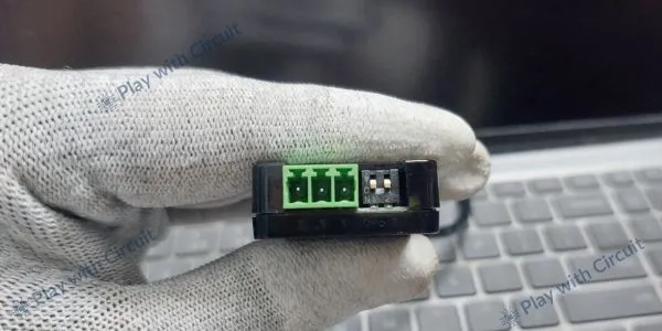
The adapter connects to the computer through a USB Type-A interface and exposes a 3-pin terminal block (CAN_H, CAN_L, GND) for connection to the CAN network. It supports CAN 2.0A (11-bit ID) and CAN 2.0B (29-bit ID) protocols with data rates up to 1 Mbps, making it suitable for most automotive and industrial CAN systems.
Key Features
The SH-C30L module typically includes the following features:
- Supports CAN 2.0A (11-bit ID) and CAN 2.0B (29-bit ID)
- Baud rate configurable up to 1 Mbps
- Compatible with SocketCAN (Linux)
- Virtual COM port support (SLCAN firmware)
- Switchable onboard 120Ω termination resistor
- 3-pin screw terminal interface
- Cross-platform compatibility (Windows, Linux, macOS)
- Firmware upgradable via DFU mode
- Low-cost open-source design base
- Bootloader jumper for firmware updates
SH-C30L CAN Adapter Pinout
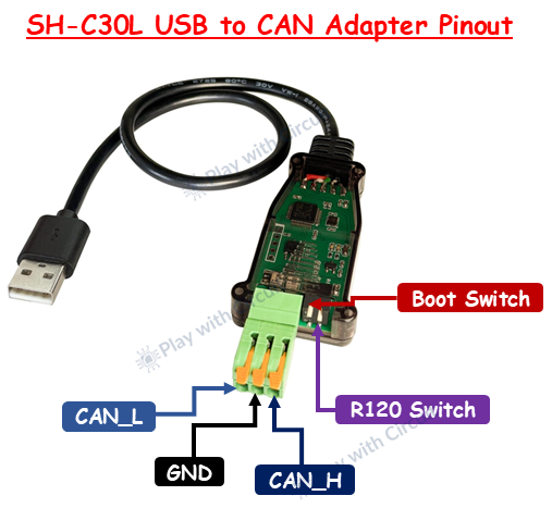
CAN_H (CAN High) This is the high-differential signal line of the CAN bus. During a data transmission, CAN_H voltage rises relative to CAN_L. It must always connect to the CAN_H line of the target network.
CAN_L (CAN Low) This is the low-differential signal line. During data transmission, CAN_L voltage drops relative to CAN_H. It must always connect to the CAN_L line of the network.
GND This is the Ground pin.
Boot Switch It is used to enter firmware/bootloader mode for updating or flashing the adapter.
R120 Switch It enables 120Ω termination resistor; turn ON only if the adapter is at the end of the CAN bus.
Why is Driver Installation Required?
When you connect the SH-C30L adapter to your computer, the operating system must recognize what kind of device it is and how to communicate with it. This is handled by drivers.
On Modern Windows (10/11)
The device is typically enumerated as a USB CDC (Communication Device Class) device. Windows includes built-in drivers for CDC devices, so no manual driver installation is usually required.
If the device appears as “Unknown USB Device,” you may need to manually install the driver file provided by open-source community; download link is given at the end. You need to right-click on the .inf file, and click install.
On Linux
Linux has built-in support for USB CDC and native CAN interfaces. No additional driver installation is required. The device will appear either as:
- /dev/ttyACMx or /dev/ttyUSBx (with SLCAN Firmware)
- can0 (with Candlelight Firmware)
On macOS
macOS also supports USB CDC devices natively. No driver installation is typically required. In summary, driver installation is required only if the OS cannot automatically recognize the USB CDC interface.
Required Software Tools
The adapter alone does not analyze CAN traffic — you need CAN software tools to send, receive, and decode messages.
For Linux Users
The most powerful environment for CAN development is Linux with SocketCAN. Install can-utils and slcand (if using SLCAN firmware)
These tools allow:
- candump → Monitor CAN traffic
- cansend → Send CAN frames
- cansniffer → Live traffic analyzer
- canbusload → Bus load measurement
If using Candlelight firmware, the adapter appears as a native CAN interface (can0), which simplifies setup.
For Windows Users
Windows does not include a native CAN stack like Linux. You must install CAN software such as:
Cangaroo (Open-source, recommended)
This tool allows:
- Real-time frame monitoring
- Manual frame transmission
- DBC file decoding
- Logging and export
For macOS Users
macOS users can use:
- Cross-platform CAN software tools
- Python CAN libraries
- Serial-based CAN applications
Functionality depends on firmware mode.
Using the Adapter on Linux with SocketCAN
Linux offers powerful built-in CAN support through a system called SocketCAN. If the adapter is running standard SLCAN firmware, you can use a tool called slcand to create a virtual CAN interface.
After installing can-utils, you can initialize the interface by specifying the baud rate. For example, for a 500 kbps bus, you configure the interface and bring it up. Once active, you can use powerful command-line tools such as candump to monitor traffic or cansend to transmit messages.
This makes Linux an extremely powerful environment for CAN debugging and development.
If the adapter uses candlelight firmware, it appears as a native CAN interface in Linux, and you can bring it up using a simple ip link command without using slcand. This improves performance and simplifies setup.
sudo ip link set can0 up type can bitrate 500000Using the SH-C30L Adapter with Python
One of the most powerful ways to interact with the SH-C30L USB to CAN adapter is by using Python. While graphical CAN tools are useful for monitoring traffic manually, Python allows developers to automate testing, log data, simulate ECUs, build dashboards, and create custom diagnostic tools.
The SH-C30L supports Python communication through the widely used python-can library. This library provides a simple interface for sending and receiving CAN frames and works across Windows, Linux, and macOS.
Installing the Required Library in Python
Before using the adapter with Python, you need to install the python-can package. This can be done easily using pip:
pip install python-canOnce installed, Python can directly interface with the SH-C30L, provided that the adapter is properly recognized by the operating system.
If you are using Linux with Candlelight firmware, the device will appear as a native CAN interface (for example, can0). On Windows or when using SLCAN firmware, the adapter appears as a serial COM port.
How to use SH-C30L USB to CAN Adapter on Windows with CAN Monitoring Software
Here, we will explore how a beginner can easily use this low-cost CAN adapter on Windows 11. For this, we need a graphical software for Windows 11 that can interact with our USB to CAN hardware. One such software is Cangaroo, which allows you to monitor CAN traffic in real time, send standard and extended frames, and even decode signals using DBC files. These tools are especially useful for automotive reverse engineering and ECU diagnostics. With the SH-C30L adapter connected, most software automatically detects the COM port or CAN interface, making it easy to start monitoring traffic within minutes.
Step 1 Connect the USB to CAN adapter to the USB port
When you connect the adapter with the PC, go to the Device Manager. The screen should look like this:
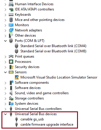
In the highlighted part, you can see the device is detected as canable gs_usb, as in the factory, the candle light firmware is pre-installed on the device. You don’t need any driver software in your pc to see this. Even if it is shown as an unknown device, the device driver information file is given in our GitHub link given in next step. You can update the driver.
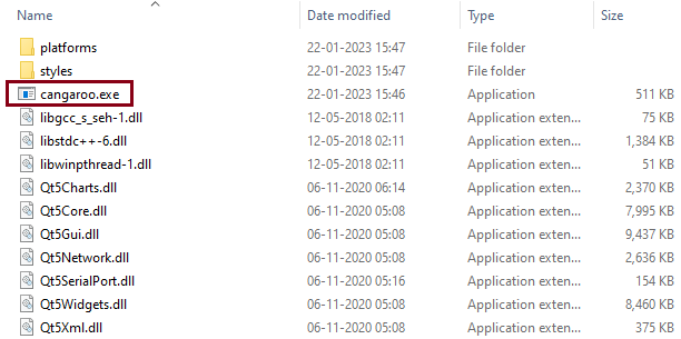
Step 2 Download Cangroo Software
You can download the software from our Github repository link. This software doesn’t need any installation. You just need to extract the zip file and run the executable as shown in figure:
Step 3 Run Cangroo Software
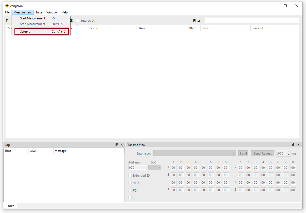
Run the software. Go to the Setup item in the Measurement Menu.
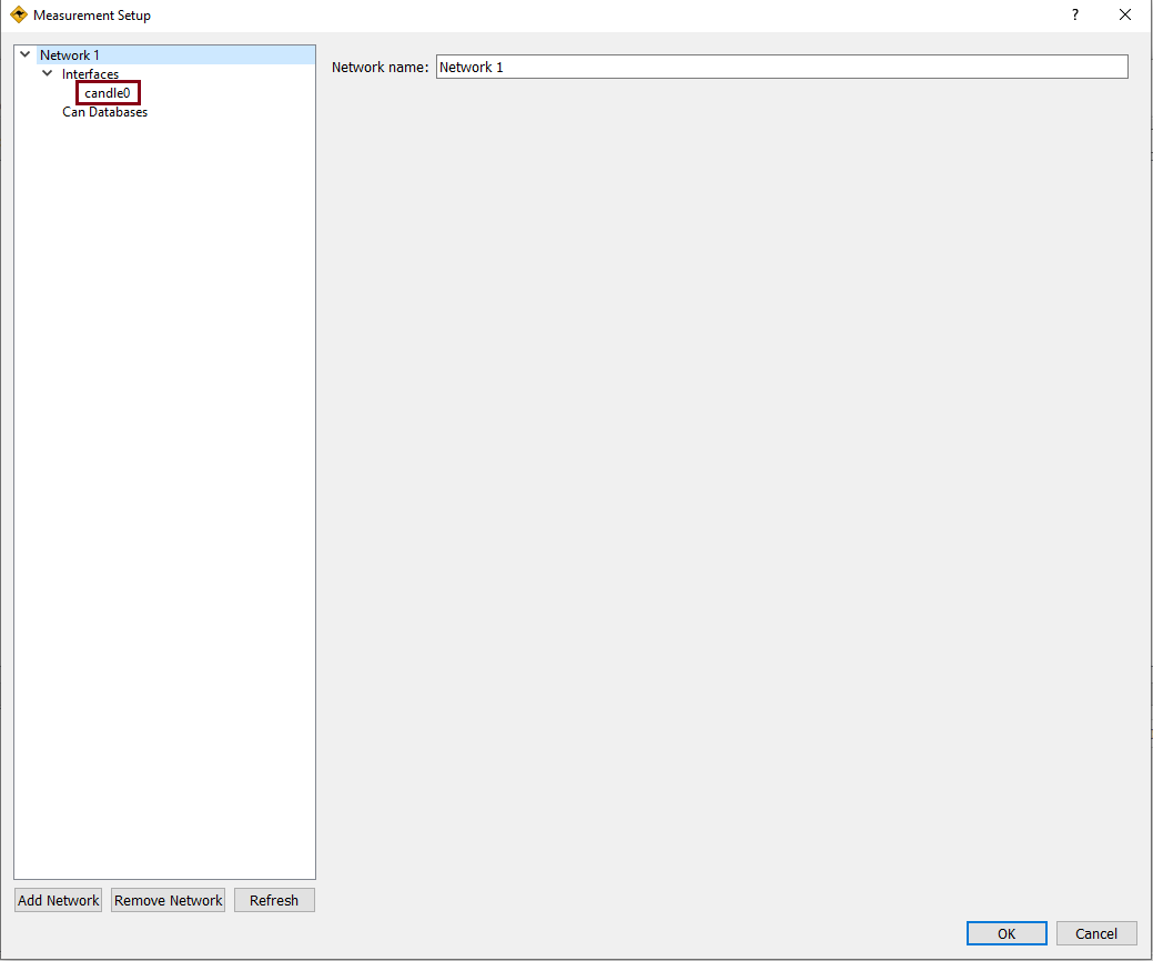
The measurement setup should look like this, it should show candle0 in options which means our device is successfully detected by the PC. Now click on the candle0 option here and open the settings.
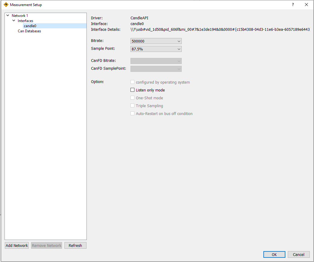
Then keep the settings as it is which comes by default. Click on OK and close the settings.
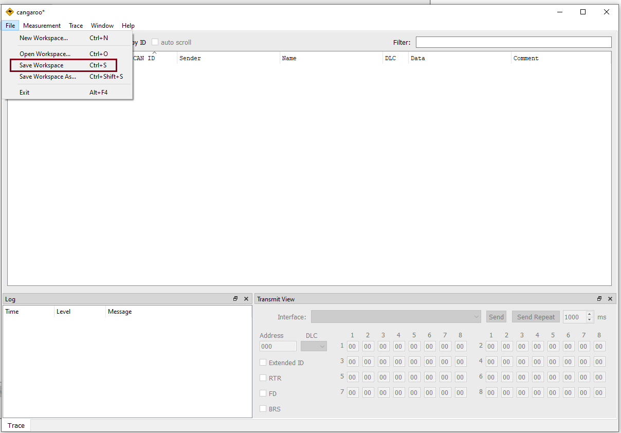
You can save the settings in File -> Save Workspace Options.
This software can also support SLCAN firmware. For that, we need to update the firmware of our adapter.
How to Update the Firmware of DSD TECH SH-C30L USB to CAN Adapter on Windows 11
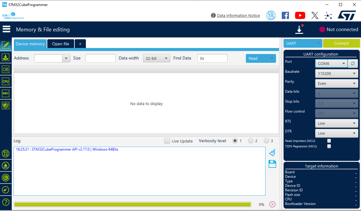
Step 1 Download and install Stm32 Cube Programmer Software version 2.17.0. The initial screen without connecting with the adapter would look like this:
Step 2 Put the adapter in firmware update mode. Now we need to toggle the boot pin in our device to put it in DFU (Device Firmware Update) Mode.
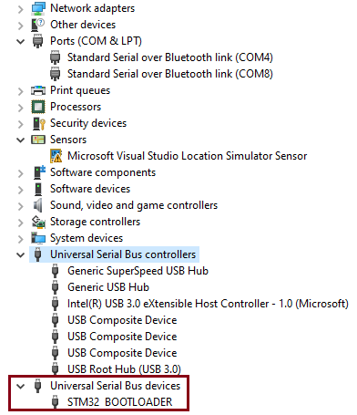
Step 3 Now, connect with the PC. After putting the device in DFU mode, connect it with the PC and open the Device Manager. It should look like this:
Step 4 Find the firmware using the GitHub link given above.
Initially, candleLight firmware is present on the device. Now update it with SLCAN firmware. Open the STM32 programmer software and then select the USB option.

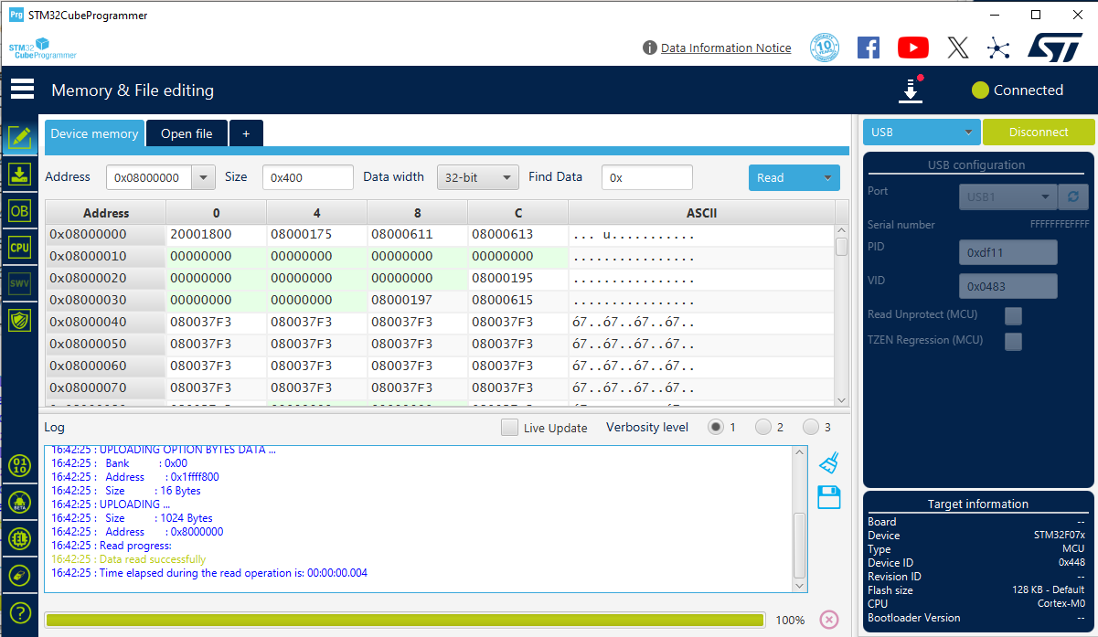
Now refresh the port, it should show USB1 and then click on connect.

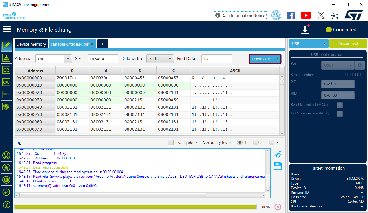
It should connect with the controller on the device and the screen should look like this.
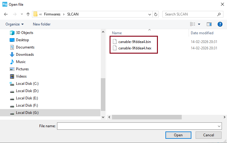
Now click on Open file and select the new firmware. This time we will select the bin file of SLCAN firmware.
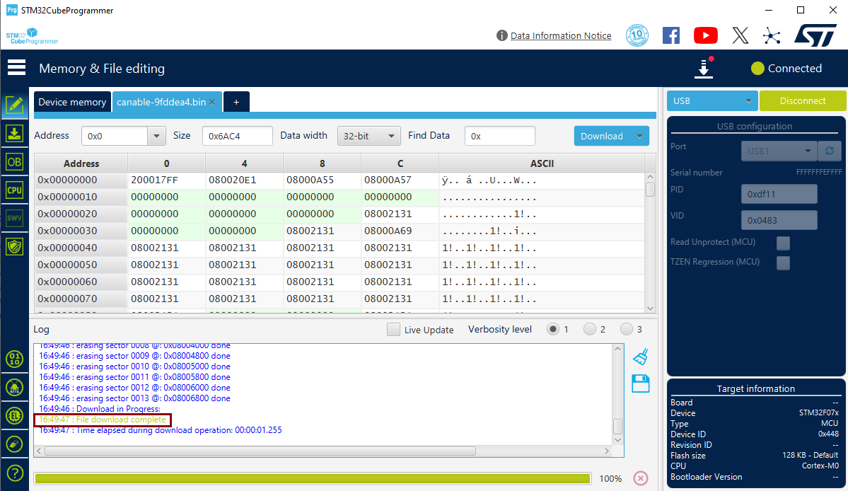
After selecting the firmware, click on download on the main screen of the programmer.
After the firmware is downloaded, the screen will show the message “file download complete”, in Log window.
Now disconnect the device from the programmer and remove the device from the USB port and toggle the boot switch to exit DFU mode.
Checking the Device with Cangroo Software using SLCAN Firmware
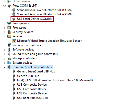
Step 1 After exiting DFU mode, reconnect the device and go to Device Manager. The device should be visible as COM port as shown below.
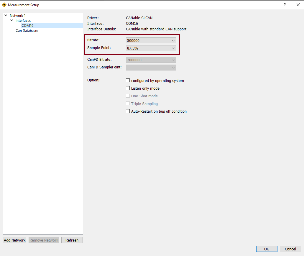
Step 2 Next, open the Cangroo Software and go to the Measurement Setup as shown below:
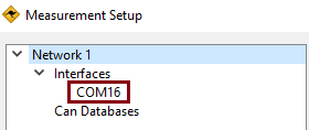
Step 3 Check the Settings. Click on the COM port name in interfaces; on our PC, it’s COM16. Keep the bitrate as 500 kbps and sample point 87.5% as it is and click on OK. This shows that after updating the firmware, the device is working OK and detected by Cangroo Software.
MCP2515 Module Overview
The MCP2515 CAN Bus Module is used for adding CAN communication to controller like ATMega32 on Arduino UNO, which doesn not include on-chip CAN peripheral. It includes two important ICs: the MCP2515 CAN controller and the TJA1050 CAN transceiver, making it a complete CAN interface solution.
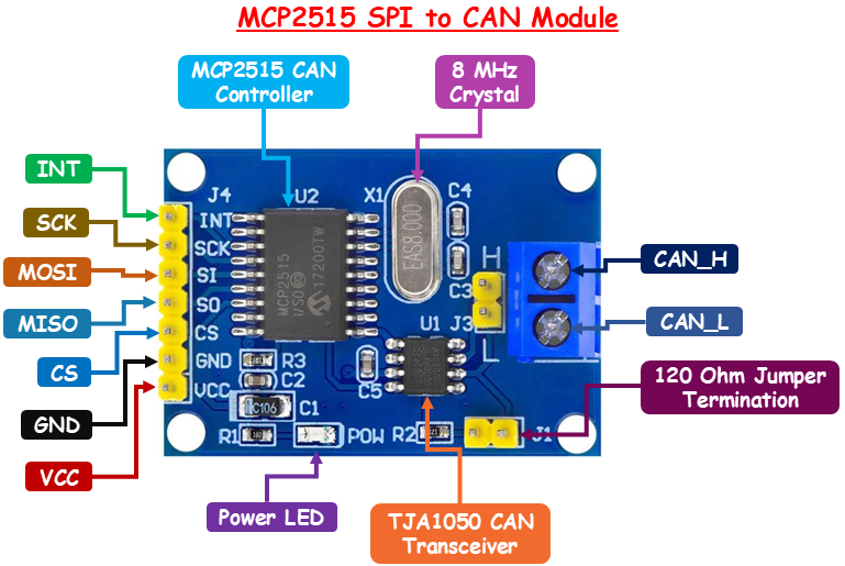
MCP2515 CAN Controller The MCP2515 is the core component of the CAN bus module and is responsible for handling all CAN communication. It can implement the CAN protocol even if the microcontroller does not have built-in CAN support. It fully supports the CAN 2.0B specification, allowing it to transmit and receive both standard and extended data frames efficiently.
MCP2515 also has built-in message filtering capabilities that allow the controller to accept only relevant messages and reject unwanted ones. Additionally, it includes an interrupt output pin (INT). This pin is triggered whenever a valid message is received.
TJA1050 CAN Transceiver The TJA1050 is responsible for interfacing the MCP2515 CAN controller with the physical CAN bus. It converts digital logic signals into differential signals required for CAN communication over the bus lines. This transceiver supports high-speed CAN communication of up to 1 Mbps.
120 ohm Jumper Termination To ensure proper signal integrity on the CAN bus, termination resistors are used at both ends of the network. The MCP2515 module includes an onboard 120-ohm termination resistor, which can be enabled or disabled using a jumper.
If the module is placed at either end of the CAN network, the termination jumper should be connected to enable the resistor. However, if the module is used as a middle node, the jumper should be removed to avoid improper termination, which can lead to signal reflections and communication errors.
Crystal Oscillator The module is equipped with an onboard crystal oscillator, typically operating at 8 MHz (though 16 MHz versions are also available). This crystal provides the timing reference required for CAN communication and ensures accurate data transmission and reception.
SPI Interface Pins
The MCP2515 module communicates with the microcontroller through SPI interface pins.
INT The INT pin is an interrupt output from the MCP2515. It goes LOW when certain events occur, such as when a new CAN message is received and stored in the receive buffer.
SCK The SCK pin (Serial Clock) is the clock signal provided by the microcontroller during SPI communication. It synchronizes the data transfer between the microcontroller and the MCP2515.
MOSI The MOSI pin, also known as MOSI (Master Out Slave In), carries data from the microcontroller to the MCP2515 module.
MISO The MISO pin, also known as MISO (Master In Slave Out), is used to send data from the MCP2515 module back to the microcontroller.
CS The CS (Chip Select) pin is used to enable communication between the microcontroller and the MCP2515 via SPI. This pin is active LOW.
GND The GND is a common ground pin.
VCC The VCC pin is used to power the MCP2515 CAN module. Connect this pin to a stable 5V source.
CAN_H The CAN_H pin represents the high line of the differential CAN bus.
CAN_L The CAN_L pin represents the low line of the CAN bus.
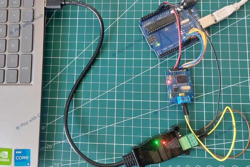
Interfacing SH-C30L with Arduino UNO using MCP2515 Module
In this section, we will be interfacing SH-C30L USB to CAN Adapter with Arduino UNO and send data from Arduino to PC and vice-versa. Since Arduino UNO doesn’t have CAN peripheral so, we use Module MCP2515 to get data from CAN lines (CAN-H and CAN-L) and convert it into SPI data which can be transmitted to Arduino UNO using its SPI peripheral lines.
Hardware Requirement
| Components | Quantity | Remarks | Where to Buy |
|---|---|---|---|
| Arduino UNO | 1 | Microcontroller board Revision R3 | Amazon |
| DSD TECH SH-C30L | 1 | USB to CAN adapter for communication with PC | Amazon |
| MCP2515 Module | 1 | Convert SPI signal to CAN-H and CAN-L | Amazon |
| Jumper Wires | Multiple | For connections between modules and Arduino UNO | Amazon |
| USB Cable Type A to B Type | 1 | For programming Arduino UNO | Amazon |
| 12V Supply Adapter | 1 | For providing power to Arduino UNO | Amazon |
Software Requirement
- Arduino IDE, Version 2.3.4 or above installed on your PC.
- mcp_can library by Coryfowler
Wiring SH-C30L CAN Adapter with Arduino
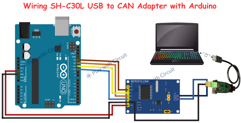
In this setup, Arduino UNO is connected to MCP2515 module using SPI peripherals and MCP2515 is further connected with SH-C30L adapter using CAN-H and CAN-L lines.
The connections between Arduino Uno and MCP2515 CAN Module are as follows:
| MCP2515 Module | Arduino Side Pin |
|---|---|
| VCC (Pin 1) | 5V pin of Arduino |
| GND (pin 2) | GND pin of Arduino |
| CS (Pin 3) | 10 |
| MISO (Pin 4) | 12 |
| MOSI (Pin 5) | 11 |
| SCK (Pin 6) | 13 |
| INT (Pin 7) | Not connected |
Once this SPI link is established, the Arduino can send commands and data to the MCP2515, which acts as a CAN controller.
The CAN communication between the MCP2515 module and the SH-C30L USB-to-CAN adapter is achieved using three essential connections: CAN_H, CAN_L, and GND. The CAN-H and CAN-L of the MCP2515 module are connected with the CAN-H and CAN-L pins of USB to CAN adapter and the GND of the USB to CAN adapter is connected to the GND of the Arduino UNO.
When the system is powered, the Arduino generates data and sends it to the MCP2515 via SPI. The MCP2515 then converts this data into CAN frames and transmits it over the CAN bus through CAN_H and CAN_L. The SH-C30L adapter receives these CAN signals and converts them into USB data, which is then sent to the PC. On the computer, CAN monitoring software can display these messages in real time.
The communication here is bidirectional. Any CAN message sent from the PC through the SH-C30L adapter travels back over the CAN bus to the MCP2515 module. The MCP2515 then notifies the Arduino via the interrupt pin, and the Arduino reads the message using SPI. This allows the Arduino to process incoming data and respond accordingly.
Here, proper CAN bus termination is essential for reliable communication. The MCP2515 module includes a J1 jumper, which, when connected, enables a 120Ω termination resistor between CAN_H and CAN_L. This resistor is required to suppress signal reflections on the CAN bus.
Since a standard CAN network requires two termination resistors (one at each end), the USB-to-CAN adapter must also provide a 120Ω termination. The SH-C30L adapter includes an R120 toggle switch, which enables or disables this internal termination resistor.
When both terminations are enabled—one on the MCP2515 (via J1 jumper) and one on the adapter (via R120 switch)—the total effective resistance across CAN_H and CAN_L becomes 60Ω, as two 120Ω resistors in parallel result in 60Ω. This is the right and expected condition for a properly terminated CAN bus.
The USB side of the SH-C30L adapter connects directly to a PC or laptop. Depending on the firmware loaded on the adapter, it is detected as either a USB-CDC device (virtual COM port) or a native USB CAN device (gs_usb).
Regardless of the firmware type, the adapter can be connected with PC software such as Cangaroo, which allows monitoring and transmitting CAN messages.
Arduino Code
The code demonstrates bidirectional CAN communication where Arduino sends periodic data and simultaneously listens for incoming messages, displaying all activity on the Serial Monitor.
/*
Code to send CAN messages from Arduino UNO to Cangroo PC Application and from PC Application to Arduino UNO
and see complete communication on Serial terminal by playwithcircuit.com
*/
#include <mcp_can.h>
#include <SPI.h>

MCP_CAN CAN0(10);  // CS pin = 10

unsigned long rxId;
unsigned char len = 0;
unsigned char rxBuf[8];

byte txData[8] = {0x00};
uint32_t counter = 0;
uint8_t data_len = 0;
void setup() {
  Serial.begin(115200);

  // Initialize MCP2515, 500 kbps, 8 MHz crystal, our module has 8 Mhz crystal on it.
  if (CAN0.begin(MCP_ANY, CAN_500KBPS, MCP_8MHZ) == CAN_OK) {
    Serial.println("MCP2515 Initialized Successfully!");
  } else {
    Serial.println("Error Initializing MCP2515...");
    while (1);
  }

  CAN0.setMode(MCP_NORMAL);  // Normal mode (required for TX/RX)
  Serial.println("CAN Ready...");
}

void loop() {
  // transmitting incremental counter data over CAN
  data_len = snprintf(txData, sizeof(txData), "%d", counter++);
  byte sendStatus = CAN0.sendMsgBuf(0x100, 0, data_len, txData);

  if (sendStatus == CAN_OK) {
    Serial.println("Message Sent Successfully!");
  } else {
    Serial.println("Error Sending Message...");
  }

  delay(1000);  // send every 1 second

  // if data is received successfully, then program goes into this if statement
  if (CAN0.checkReceive() == CAN_MSGAVAIL) {

    CAN0.readMsgBuf(&rxId, &len, rxBuf);

    Serial.print("Received ID: 0x");
    Serial.print(rxId, HEX);

    Serial.print("  DLC: ");
    Serial.print(len);

    Serial.print("  Data: ");

    for (int i = 0; i < len; i++) {
      Serial.print(rxBuf[i], HEX);
      Serial.print(" ");
    }
    Serial.println();
  }
}
Code Explanation
The sketch begins by including the required libraries:
<SPI.h> → This is required because the CAN module MCP2515 communicates using SPI protocol.
<mcp_can.h> → This library is used to interact with the MCP2515 CAN controller.
Then, we create an object that defines how the Arduino connects to the CAN module. The number 10 represents the Chip Select (CS) pin, which tells the Arduino which SPI device it is communicating with. So, this line establishes the communication link between Arduino UNO and MCP2515 CAN module.
#include <mcp_can.h>
#include <SPI.h>

MCP_CAN CAN0(10);  // CS pin = 10
Next, we define several variables to handle CAN communication. For receiving data, we declare rxId, len and rxBuf[8]. The rxId stores the identifier of the incoming CAN message, len stores how many bytes were received, and rxBuf is an array that can hold up to 8 bytes, which is the maximum size of a standard CAN message.
For transmitting data, we declare txData[8], which will store the outgoing message. We also define a counter variable that starts from zero and increases over time. This counter is what we will send as data, making it easy to observe changes in its values. Finally, data_len stores the length of the data being sent.
unsigned long rxId;
unsigned char len = 0;
unsigned char rxBuf[8];

byte txData[8] = {0x00};
uint32_t counter = 0;
uint8_t data_len = 0;
In the setup function, we start serial communication at a 115200 baud rate to view the output on Serial Monitor. This allows us to print messages on the Serial Monitor, which is extremely useful for debugging and understanding what is happening inside the code.
After that, we initialize the CAN module using CAN0.begin(). Here, three parameters are passed: MCP_ANY, CAN_500KBPS, and MCP_8MHZ. This means the module will accept all messages, operate at a speed of 500 kbps, and use an 8 MHz crystal oscillator.
The code checks whether initialization is successful. If it is, it prints a success message. If not, it prints an error and stops execution using an infinite loop (while(1);). This ensures the program doesn’t continue if the CAN module is not working.
void setup() {
  Serial.begin(115200);

  // Initialize MCP2515, 500 kbps, 8 MHz crystal, our module has 8 Mhz crystal on it.
  if (CAN0.begin(MCP_ANY, CAN_500KBPS, MCP_8MHZ) == CAN_OK) {
    Serial.println("MCP2515 Initialized Successfully!");
  } else {
    Serial.println("Error Initializing MCP2515...");
    while (1);
  }
Inside the loop() function, the first task is to prepare data for transmission. The function snprintf() is used to convert the counter value into a string and store it inside the txData array. This is important because CAN messages are sent as bytes, and this function helps format the data properly. At the same time, the counter is incremented (counter++), so each message contains a new value.
After preparing the data, we send it using CAN0.sendMsgBuf(). The first parameter 0x100 is the CAN ID, which acts like an address or identifier for the message. The second parameter 0 indicates that we are using a standard frame (not extended). The third parameter is the length of the data, and the last parameter is the actual data buffer.
The code then checks whether the message was sent successfully. If yes, it prints a success message; otherwise, it prints an error. This feedback is useful for debugging communication issues.
After sending the message, we use delay(1000) to wait for 1 second before sending the next message.
void loop() {
  // transmitting incremental counter data over CAN
  data_len = snprintf(txData, sizeof(txData), "%d", counter++);
  byte sendStatus = CAN0.sendMsgBuf(0x100, 0, data_len, txData);

  if (sendStatus == CAN_OK) {
    Serial.println("Message Sent Successfully!");
  } else {
    Serial.println("Error Sending Message...");
  }
  delay(1000);  // send every 1 second
After handling transmission, the program checks whether any CAN message has been received using CAN0.checkReceive(). If a message is available, the program enters the receiving block.
Once a message is detected, the function CAN0.readMsgBuf() is used to extract the data. This function fills three variables: rxId (message ID), len (data length), and rxBuf (actual data bytes).
After reading the message, the program prints all the details to the Serial Monitor. It first prints the CAN ID in hexadecimal format, then the DLC (Data Length Code), and finally the data itself.
To print the data, a loop runs from 0 to len, printing each byte in hexadecimal format. This allows you to clearly see what data was received over the CAN bus.
  // if data is received successfully, then program goes into this if statement
  if (CAN0.checkReceive() == CAN_MSGAVAIL) {

    CAN0.readMsgBuf(&rxId, &len, rxBuf);

    Serial.print("Received ID: 0x");
    Serial.print(rxId, HEX);

    Serial.print("  DLC: ");
    Serial.print(len);

    Serial.print("  Data: ");

    for (int i = 0; i < len; i++) {
      Serial.print(rxBuf[i], HEX);
      Serial.print(" ");
    }
    Serial.println();
  }
}
Output
After uploading the code, the CAN communication can be observed on both the Arduino IDE Serial Monitor and the Cangaroo interface.
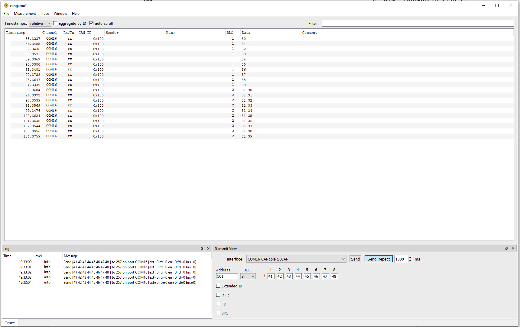
Sending/Receiving Data on Cangroo Software
The transmitted data from Arduino appears in the Trace window as incoming (Rx) messages. The CAN ID (e.g., 0x100) and corresponding data bytes can be observed updating continuously, indicating successful transmission from the Arduino.
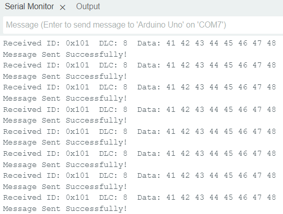
Arduino IDE Terminal
On the Arduino IDE Serial Monitor, the system prints the transmission status and received CAN messages. You will see a confirmation message whenever data is sent successfully, along with details of any received message such as CAN ID, data length (DLC), and data bytes.
Troubleshooting Guide
If the system does not work as expected, check the following points:
Issue 1: Why is MCP2515 initialization failing?
This usually indicates SPI communication failure or incorrect oscillator setting (8MHz / 16MHz). Also, check CS pin configuration and wiring.
Issue 2: Why is no data visible in Cangaroo software?
Check if the correct COM port is selected, the baud rate matches the CAN network, and the adapter is properly detected. Also, verify CAN wiring and termination.
Issue 3: Why am I getting random or corrupted CAN data?
This is usually due to improper termination, electrical noise, or baud rate mismatch. Ensure two 120Ω resistors are present and wiring is correct.
Issue 4: Why is MCP2515 working but no data appears on Serial Monitor?
Check if the code is correctly reading incoming messages and Serial Monitor baud rate is set properly. Also, ensure that data is actually being transmitted on the CAN bus.
Issue 5: Why CAN communication not working?
Common causes include missing termination resistors, incorrect wiring, mismatched baud rate, faulty connections, or wrong CAN mode (not set to normal mode).
FAQ’S
What is a USB to CAN adapter and how does it work?
A USB to CAN adapter converts USB signals from a PC into CAN protocol signals and vice versa. It acts as a bridge, allowing a computer to send, receive, and monitor CAN messages over the CAN bus.
How does Arduino communicate over CAN bus?
Arduino communicates over CAN using the MCP2515 module via SPI protocol. The MCP2515 converts Arduino data into CAN frames and transmits them over CAN_H and CAN_L lines.
What are CAN_H and CAN_L in CAN communication?
CAN_H and CAN_L are differential signal lines used to transmit data. The voltage difference between them represents binary data, making CAN highly resistant to electrical noise.
What is CAN ID and why is it important?
CAN ID is a unique identifier for each message on the CAN bus. It determines message priority and helps nodes decide whether to process or ignore a message.
What software can be used to monitor CAN communication on PC?
Software like Cangaroo is used to monitor, send, and analyze CAN messages in real time through a USB-to-CAN adapter.
