
From navigation apps and vehicle tracking system to smartwatches and drones, GPS technology has become an important part of our everyday lives. But have you ever wondered how these tracking devices actually work? What does it take to build your own GPS tracker?
Let’s build one and find out. In this article, we will build a GPS Tracker using the Reyax RYS352A GNSS module and the Heltec WiFi LoRa 32 V4 development board. The tracker continuously acquires location data from navigation satellites, displays the current latitude and longitude on the onboard display of the board, and allows you to view its location and travel path on a map through a simple web page that can be accessed from any device connected to the same mobile hotspot network.
One of the biggest advantages of this project is that it does not require any paid cloud platform, account registration, or complex server setup. Everything runs locally, making the system simple, cost-effective, and easy to deploy for learning, experimentation, and real-world tracking applications. Let’s get started!
What this GPS Tracker Does?
- The Reyax RYS352A GNSS module receives location data from multiple satellite constellations.
- The Heltec WiFi LoRa 32 V4 receives the GNSS data, decodes the NMEA sentences and extracts latitude, longitude coordinates and satellite count.
- The current coordinates and satellite count are displayed on the Heltec board’s onboard display.
- The ESP32 connects to a mobile hotspot for network access.
- The ESP32 hosts a browser-based GPS tracking webpage, eliminating the need for an external cloud platform.
- A webpage displays the current location and travelled path on a map in real time.
- Any smartphone or computer connected to the same Wi-Fi network can access the tracking webpage using a web browser.
Why do we call it a GPS Tracker if it uses a GNSS module?
Here we we are using the term GPS Tracker because is widely used for this type of location-tracking device and is familiar to most users. However, the RYS352A used in this project is actually a multi-GNSS receiver, which can receive signals from multiple satellite constellations.
What is GNSS and How it works?
Global Navigation Satellite System (GNSS) is a network of satellites that provide navigation, positioning, and timing information of a receiver anywhere on Earth. Unlike GPS, which is limited to a single satellite constellation operated by the USA, GNSS includes multiple global navigation satellite systems such as GPS (USA), GLONASS (Russia), Galileo (EU), BeiDou (China) and QZSS (Japan). Having access to multiple satellites improves positioning accuracy, availability and reliability at all times.
The GNSS system works through a network of satellites orbiting the Earth. Each satellite continuously transmits radio signals containing precise timing and location data. A GNSS receiver on the ground receives these signals from multiple satellites simultaneously. It measures the time taken for these signals to reach it and uses this information to calculate the distance to each satellite.
After measuring its distance from at least three satellites, the GNSS receiver uses a technique called trilateration to determine its position. Each calculated distance forms an imaginary sphere around each satellite. The point where the three spheres intersect provides the receiver’s location on the Earth’s surface, providing its latitude and longitude (two-dimensional position).
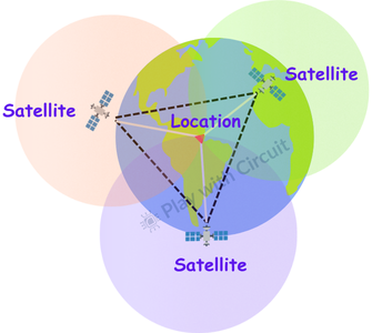
To determine the third coordinate—altitude (elevation)—the receiver requires signals from a fourth satellite. Using the additional distance measurement, the receiver calculates its height above the Earth’s surface, resulting in a complete three-dimensional position fix consisting of latitude, longitude, and altitude.
In general, the more satellites the GNSS receiver can track simultaneously, the more accurate and reliable the calculated position becomes.
Reyax RYS352A GNSS Module
The Reyax RYS352A GNSS Module is a compact and high-sensitivity multi-GNSS receiver. The module is based on the Airoha AG3352 GNSS engine and supports multiple satellite which helps providing better satellite availability, faster position fixes, and improved positioning accuracy.
The module communicates using a 3.3V UART serial interface, which allows it to connect easily with microcontrollers. It outputs standard NMEA 0183 V4.10 data sentences.
Key Features of RYS352A GNSS Module
- Multi-GNSS support: Global Positioning System GPS, GLONASS, Galileo, and BeiDou support
- Supports satellite-based augmentation systems (SBAS) such as WAAS, EGNOS, MSAS, and GAGAN
- Based on Airoha AG3352 GNSS engine
- Standard UART serial communication interface
- Operates on 3.3V supply
- Supports NMEA 0183 V4.10 protocol
- Integrated embedded GNSS antenna
- Built-in SAW filter, LNA, and TCXO for improved signal reception
- Indoor and outdoor path detection and compensation
- RTC battery backup for faster satellite reacquisition
- TXD and PPS LED indicators
- 12 multi-tone active interference cancellers
- Compact and lightweight design
- Max. 10Hz Navigation update rate
Reyax GNSS Module Hardware Overview
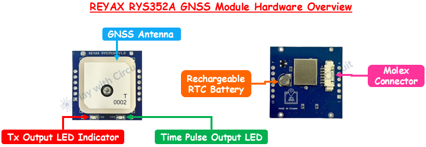
GNSS Antenna The GNSS antenna captures RF signals transmitted by satellites. This antenna is integrated into the module.
TX Output LED Indicator The red TXD LED flashes whenever the module transmits NMEA data through its UART TX pin.
Time Pulse (1PPS) LED Indicator The green 1PPS LED indicates the status of the module’s one-pulse-per-second (1PPS) output. Once the receiver acquires a valid GNSS fix, the LED pulses once every second
Rechargeable RTC Battery The module includes a rechargeable RTC backup battery, which maintains the real-time clock and preserves satellite-related data when the main power is removed.
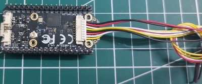
Molex connector This 6-pin Molex connector allows the RYS352A to be easily connected to the controller.
GNSS Module Pinout
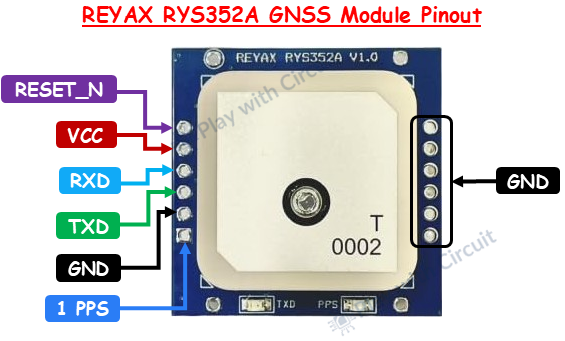
VCC This is power supply pin.
GND This is a ground pin.
TXD Continuously transmits NMEA 0183 sentences.
RXD Receives UART commands for configuring the GNSS module.
1PPS (Pulse Per Second) The 1PPS pin provides a highly accurate timing pulse that occurs once every second.
RESET_NThis pin Resets the module when driven LOW for at least 100 ms.
GNSS Data Output (NMEA Protocol)
The RYS352A GNSS module communicates using standard NMEA sentences at a default baud rate of 115200 bps. The NMEA protocol works by transmitting data as a series of human-readable ASCII text sentences.
These sentences contain important navigation information including latitude, longitude, altitude, speed, date, time, satellite count, and UTC time.
Example NMEA Sentence:
$GPGGA,123519,4807.038,N,01131.000,E,1,08,0.9,545.4,M,46.9,M,,*47| Field | Value | Description |
|---|---|---|
| $ | Start of NMEA sentence | Indicates the beginning of a message |
| GPGGA | Message Type | GPS Fix Data sentence |
| 123519 | UTC Time | 12:35:19 UTC |
| 4807.038,N | Latitude | 48°07.038' North |
| 01131.000,E | Longitude | 11°31.000' East |
| 1 | Fix Quality | 0 = Invalid, 1 = GPS Fix, 2 = DGPS Fix |
| 08 | Satellites Used | 8 satellites used for position calculation |
| 0.9 | HDOP | Horizontal Dilution of Precision (lower is better) |
| 545.4 | Altitude | Height above mean sea level |
| M | Units | Altitude in meters |
| 46.9 | Geoid Separation | Difference between mean sea level and Earth's ellipsoid |
| M | Units | Meters |
| DGPS Station ID | (empty) | No DGPS station being used |
| *47 | Checksum | Used for data integrity verification |
The ESP32 reads these NMEA sentences from the RYS352A module through UART communication. The firmware extracts useful information such as latitude, longitude, altitude, and satellite status, which are then displayed on the onboard screen and used to update the tracking map.
Heltec WiFi LoRa 32 V4
The Heltec WiFi LoRa 32 V4 serves as the main controller in this project. It receives GNSS data from the RYS352A module through UART communication, processes the location information, displays coordinates on the onboard screen, and hosts the web interface used for tracking.
If you’re new to this development board, you can read our detailed getting started guide before proceeding with this project.
How to Get Started with Heltec WiFi LoRa 32 V4
Explore Heltec LoRa 32 board including its hardware architecture, pinout and installing Heltec ESP32 framework.
How the GPS Tracker Works?
The GPS tracker consists of three main parts: the RYS352A GNSS module, the Heltec WiFi LoRa 32 V4 development board, and a mobile phone acting as both a Wi-Fi hotspot and a monitoring device.
![]()
When the system is powered on, the ESP32 first connects to the Wi-Fi hotspot whose credentials are preconfigured in the source code. Therefore, before using the tracker, ensure that the mobile hotspot is enabled and the phone has an active internet connection. Once the ESP32 successfully connects to the hotspot, its assigned IP address is displayed on the onboard OLED display. Later, this same IP address will be used to access the tracking page from a web browser.
At the same time, the RYS352A GNSS module starts searching for available satellites. As soon as a valid satellite fix is obtained, the module begins transmitting NMEA data to the ESP32 through the UART interface. The ESP32 continuously receives location information from the GNSS module. When the IP address displayed on the OLED screen is entered into a web browser, the ESP32 sends a web page to the browser and acts as a small web server. The page, created using HTML, CSS, and JavaScript, displays the current location and tracking information.
The ESP32 extracts the required information and displays the current latitude, longitude, and the number of connected satellites on the onboard OLED display. At this stage, internet connectivity is not required for obtaining location data because all positioning information comes directly from GNSS satellites.
The web page displays the current location on a map using a red marker. As the tracker moves, the marker position is updated continuously and previous positions are retained, creating a trail, allowing users to visualize the travel path in real time.
The map image is loaded from OpenStreetMap site. If internet access is unavailable, the map tiles will not be displayed. However, the tracker will continue receiving satellite data, and the web page will still show the location marker and its travel trail based on the coordinates received from the GNSS module.
Hardware Requirement
| Component | Quantity | Purpose | Where to Buy |
|---|---|---|---|
| Heltec WiFi LoRa 32 V4 | 1 | Main development board that processes GNSS data | Amazon |
| REYAX RYS352A GNSS Module | 1 | Receives satellite signals and provides real-time location data | Amazon |
| Jumper Wires | As required | Used for making connections between components | Amazon |
| USB Cable (USB A to USB C type cable) | 1 | Used to program and power the Heltec board during development | Amazon |
| Breadboard | 1 | Used for prototyping the circuit | Amazon |
| Lithium Battery 12 volt | 1 | Powers the breadboard power supply | Amazon |
| Breadboard power supply module | 1 | Regulates the battery voltage and supplies the required operating voltage to the circuit | Amazon |
Software Requirement
- Arduino IDE version 2.3.9 or latest available version.
- Heltec ESP32 Dev-Boards Library, by Heltec Automation, version 2.1.6 or latest version.
Circuit Diagram for GPS Tracker
The circuit diagram of the GPS tracker is straightforward and requires only a few connections between the Heltec V4 board and the RYS352A GNSS module. The complete circuit diagram is shown below.
![]()
The RYS352A GNSS module operates from a 3.3V supply. Therefore, its VCC pin is connected to the 3.3V supply of the breadboard power supply, while the GND pin is connected to the common ground. These connections provide power to the GNSS module.
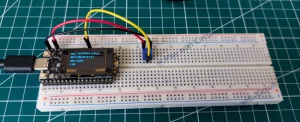
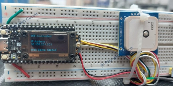
For data communication, the TX pin of the RYS352A module is connected to GPIO38 (11th pin of header J3) of the Heltec board, which serves as the UART receive (RX) pin for this project. Through this connection, the GNSS module transmits NMEA sentences to the ESP32. The complete hardware setup after assembling all the components is shown below.
![]()
Alternatively, the RYS352A GNSS module can be connected directly to the dedicated GNSS Molex connector available on the Heltec V4 board.
The RYS352A GNSS module’s power (VCC) pin is connected to Pin 7, the GND pin is connected to Pin 8, and the TX pin is connected to Pin 4 of the Molex connector. The complete circuit connection is shown below.
An additional feature of the Heltec board is the ability to control the GNSS module’s power through the VGNSS_CTRL pin (GPIO34). The required switching circuitry is already implemented on the board, and power control is handled entirely through software. This feature will only work when GNSS module is connected to the Heltec board via molex connector.
Here we’ve also used a breadboard power supply module to provide a stable and regulated power source to the circuit. Since the circuit is powered by a 12 V battery, the breadboard power supply converts the input voltage to the required 5 V or 3.3 V output, protecting the connected components from over-voltage and eliminating the need for separate voltage regulator circuits.
Code for GPS Tracker
The following code demonstrates how to build a GPS tracker. It reads and processes GNSS data, displays the current coordinates on the onboard OLED display, and hosts a web-based tracking interface that shows the tracker’s location and travel path on an OpenStreetMap map.
#include "HT_TinyGPS++.h"
#include <Wire.h>
#include "HT_SSD1306Wire.h"
#include <WiFi.h>
#include <WebServer.h>

// these pins controls the power to the GNSS module, the GNSS module is connected to connector P3 of the Heltec V4 board
#define VGNSS_CTRL 34
// this pin controls the power to the OLED module
#define OLED_CTRL  36

// pins for receiving and transmitting data from/to the GNSS module
#define GPS_RX 38
#define GPS_TX 39

// create a UART communication object to communicate with GNSS module over UART 1
HardwareSerial GPS(1);

// create a gps object to parse NMEA data from GNSS module
TinyGPSPlus gps;

// create a display object to drive onboard 128x64 OLED display
static SSD1306Wire display(0x3c, 500000, SDA_OLED, SCL_OLED, GEOMETRY_128_64, RST_OLED);

// wifi ssid and password
char ssid[] = "HotspotName";
char pass[] = "HotspotPW";

// create an HTTP web server object named server that listens for browser requests on port 80 and allows the ESP32 to host web pages
WebServer server(80);

// variables to save GPS data
double latitude  = 0.00;
double longitude = 0.00;
int satellites   = 0;

// this function is the GPS data provider for our webpage, when the browser visits our page then this function runs and sends back the latest GPS information.
void handleGPS()
{
    String json =
        "{\"lat\":" +
        String(latitude, 6) +
        ",\"lon\":" +
        String(longitude, 6) +
        ",\"sat\":" +
        String(satellites) +
        "}";

    server.send(200, "application/json", json);
}

// this function  creates an HTML webpage and sends that webpage to the browser
void handleRoot()
{
    String html = R"rawliteral(

    <!DOCTYPE html>
    <html>

    <head>

    <meta charset="utf-8">
    <meta name="viewport" content="width=device-width, initial-scale=1.0">

    <title>Heltec GNSS Tracker</title>

    <link rel="stylesheet"
    href="https://unpkg.com/leaflet@1.9.4/dist/leaflet.css"/>

    <script src="https://unpkg.com/leaflet@1.9.4/dist/leaflet.js"></script>

    <style>

    body
    {
        font-family: Arial;
        margin: 10px;
    }

    #map
    {
        height: 500px;
        width: 100%;
    }

    .info
    {
        font-size: 20px;
        margin: 10px 0;
    }

    </style>

    </head>

    <body>

    <h2>Heltec GNSS Tracker</h2>

    <div class="info">
    Latitude :
    <span id="lat">0</span>
    </div>

    <div class="info">
    Longitude :
    <span id="lon">0</span>
    </div>

    <div class="info">
    Satellites :
    <span id="sat">0</span>
    </div>

    <div id="map"></div>

    <script>

    var map = L.map('map').setView([0.00,0.00], 18);

    L.tileLayer('https://tile.openstreetmap.org/{z}/{x}/{y}.png', { maxZoom:19 }).addTo(map);

    var marker = L.marker( [18.5204,73.8567] ).addTo(map);

    var pathPoints = [];

    var trail = L.polyline(pathPoints,{color:'red', weight:4 }).addTo(map);

    function updateGPS()
    {
        fetch('/gps')
        .then(response => response.json())
        .then(data =>
        {
            document.getElementById('lat').innerHTML = data.lat;
            document.getElementById('lon').innerHTML = data.lon;
            document.getElementById('sat').innerHTML = data.sat;

            var point = [data.lat,data.lon];
            marker.setLatLng(point);
            pathPoints.push(point);
            if(pathPoints.length > 1000)
            {
                pathPoints.shift();
            }

            trail.setLatLngs(pathPoints);
            map.panTo(point);
        });
    }

    setInterval(updateGPS, 3000);

    updateGPS();

    </script>

    </body>
    </html>

    )rawliteral";

    server.send(200, "text/html", html);
}

void setup()
{
    int x_cord = 0;
    int y_cord = 30;
    // init uart at baudrate 115200 bps
    Serial.begin(115200);

    // Enable GNSS power
    pinMode(VGNSS_CTRL, OUTPUT);
    digitalWrite(VGNSS_CTRL, LOW);

    delay(500);

    // OLED ON
    pinMode(OLED_CTRL, OUTPUT);
    digitalWrite(OLED_CTRL, LOW);

    display.init();
    display.clear();
    display.display();

    // Start GPS UART
    GPS.begin(115200, SERIAL_8N1, GPS_RX, GPS_TX);

    Serial.println("GNSS Started");

    display.drawString(0, 0, "GNSS Started");
    display.display();

    // connect to wifi network using ssid and password provided
    WiFi.begin(ssid, pass);

    Serial.print("Connecting");
    display.drawString(0, 20, "Connecting to wifi");
    display.display();

    // print ..... on serial if not connected to wifi
    while (WiFi.status() != WL_CONNECTED)
    {
        delay(500);
        Serial.print(".");
        display.drawString(x_cord, y_cord, ".");
        display.display();
        x_cord+=2;
        if(x_cord>128)
        {
            x_cord = 0;
            y_cord = y_cord + 10;
        }
    }

    display.clear();
    display.display();

    Serial.println();
    Serial.println("WiFi Connected");

    Serial.print("IP Address : ");
    Serial.println(WiFi.localIP());

    server.on("/", handleRoot);
    server.on("/gps", handleGPS);

    server.begin();

    Serial.println("Web Server Started");

    display.drawString(0, 0,  "WiFi Connected");
    display.drawString(0, 20, "IP Address : ");
    display.drawString(0, 30, WiFi.localIP().toString());
    display.drawString(0, 50, "Web Server Started");
    display.display();
}

void loop()
{
    // this function continuously checks if there is a request from browser
    server.handleClient();

    unsigned char gpsdata;
    while (GPS.available())
    {
        gpsdata = GPS.read();
        // this function gets the gps data and parse it character by character
        gps.encode(gpsdata);
        Serial.write(gpsdata);
    }

    if (gps.location.isUpdated())
    {
        latitude = gps.location.lat();
        longitude = gps.location.lng();
        satellites = gps.satellites.value();

        Serial.print("Latitude : ");
        Serial.print(latitude, 6);

        Serial.print("  Longitude : ");
        Serial.print(longitude, 6);

        Serial.print("  Satellites : ");
        Serial.println(satellites);

        display.clear();

        display.setFont(ArialMT_Plain_10);

        display.drawString(0, 0, "GPS Data");

        display.drawString(0, 20, "LAT:");

        display.drawString(30, 20, String(latitude, 6));

        display.drawString(0, 30, "LON:");

        display.drawString(30, 30, String(longitude, 6));

        display.drawString(0, 40, "SAT:");

        display.drawString(30, 40, String(satellites));

        display.display();
    }
}
Code Explanation
Including Required Libraries
The program begins by including the necessary libraries:
HT_TinyGPS++.h parses NMEA sentences received from the GNSS module.
Wire.h enables I2C communication.
HT_SSD1306Wire.h controls the OLED display of Heltec board.
WiFi.h allows the ESP32 to connect to a wireless network.
WebServer.h enables the ESP32 to host a web page.
#include "HT_TinyGPS++.h"
#include <Wire.h>
#include "HT_SSD1306Wire.h"
#include <WiFi.h>
#include <WebServer.h>
Defining Hardware Pins
Next, the GPIO pins used for controlling the GNSS module, OLED display, and UART communication are defined.
VGNSS_CTRL(GPIO34) controls power to the GNSS connector.OLED_CTRL(GPIO36) controls power to the OLED display.GPS_RX(GPIO38) receives data from the GNSS module.GPS_TX(GPIO39) can transmit data back to the GNSS module if required.
// these pins controls the power to the GNSS module, the GNSS module is connected to connector P3 of the Heltec V4 board
#define VGNSS_CTRL 34
// this pin controls the power to the OLED module
#define OLED_CTRL  36

// pins for receiving and transmitting data from/to the GNSS module
#define GPS_RX 38
#define GPS_TX 39
Creating Objects and Configuring Wi-Fi Credentials
First we create a UART1 communication object named GPS which is responsible for communicating with the RYS352A GNSS module.
Next, we create an object of the TinyGPS++ library, which automatically parses the NMEA sentences received from the GNSS module and extracts useful navigation information.
Next, we created an object for controlling the onboard OLED display. The parameters specify the display’s I²C address (0x3C), communication speed, SDA and SCL pins, display resolution, and reset pin. This object is used to display the Wi-Fi connection status, IP address, latitude, longitude, and satellite count.
Next we define the variables that store the Wi-Fi network name (SSID) and password that the ESP32 uses to connect to a mobile hotspot. Here you need to add your WiFi Name and password in the code.
// create a UART communication object to communicate with GNSS module over UART 1
HardwareSerial GPS(1);

// create a gps object to parse NMEA data from GNSS module
TinyGPSPlus gps;

// create a display object to drive on board 128x64 OLED display
static SSD1306Wire display( 0x3c, 500000, SDA_OLED, SCL_OLED, GEOMETRY_128_64, RST_OLED);

// wifi ssid and password
char ssid[] = "HotspotName";
char pass[] = "HotspotPW";
Configuring the Web Server
The ESP32 hosts a web page that displays the current GPS location and travel path. For this, we first create a web server object named server that listens for incoming browser requests on port 80, which is the default port used for HTTP communication.
Then we declare 3 global Variables to Store GPS Data:
- latitude stores the current latitude.
- longitude stores the current longitude.
- satellites stores the number of satellites currently used for positioning.
Next, we create a custom function handleGPS() that provides the latest GPS information to the web page. Whenever the web page requests the /gps URL, this function is executed. It creates a JSON string containing the latest latitude, longitude, and satellite count.
Finally, we send this JSON data back to the browser.
// create an HTTP web server object named server that listens for browser requests on port 80 and allows the ESP32 to host web pages
WebServer server(80);

// variables to save GPS data
double latitude  = 0.00;
double longitude = 0.00;
int satellites   = 0;

// this function is the GPS data provider for our webpage, when the browser visits our page then this function runs and sends back the latest GPS information.
void handleGPS()
{
    String json =
        "{\"lat\":" +
        String(latitude, 6) +
        ",\"lon\":" +
        String(longitude, 6) +
        ",\"sat\":" +
        String(satellites) +
        "}";

    server.send(200, "application/json", json);
}
Creating the Tracking Webpage
The handleRoot() function is a custom function that creates the complete GPS tracking webpage and sends it to the browser whenever a user enters the ESP32’s IP address.
The complete HTML webpage is stored inside a raw string literal. It is used for embedding large HTML, CSS, and JavaScript code directly inside an Arduino sketch.
Now, we create the basic webpage structure.
<!DOCTYPE html> declares the document as an HTML5 webpage.
<meta charset="utf-8"> enables UTF-8 character encoding.
<meta name="viewport"> makes the webpage responsive on mobile devices.
<title> specifies the title displayed on the browser tab.

// this function  Creates an HTML webpage and Sends that webpage to the browser
void handleRoot()
{
    String html = R"rawliteral(

    <!DOCTYPE html>
    <html>

    <head>

    <meta charset="utf-8">
    <meta name="viewport" content="width=device-width, initial-scale=1.0">

    <title>Heltec GNSS Tracker</title>
Next we include the Leaflet mapping library. It is a lightweight JavaScript library used to display interactive maps. It works together with OpenStreetMap to visualize the GPS location and travel path of the tracker.
Then we style the webpage. We set the page font to Arial, add spacing around the page, create a responsive map area and format the latitude, longitude, and satellite information.
  <link rel="stylesheet"
    href="https://unpkg.com/leaflet@1.9.4/dist/leaflet.css"/>

    <script src="https://unpkg.com/leaflet@1.9.4/dist/leaflet.js"></script>

    <style>

    body
    {
        font-family: Arial;
        margin: 10px;
    }

    #map
    {
        height: 500px;
        width: 100%;
    }

    .info
    {
        font-size: 20px;
        margin: 10px 0;
    }

    </style>

    </head>
Next, we create the User Interface. The following HTML creates the information panel and map container. Initially, the latitude, longitude, and satellite count are displayed as 0.
The <div id="map"> element reserves space where the interactive OpenStreetMap map will be displayed.
 <body>

    <h2>Heltec GNSS Tracker</h2>

    <div class="info">
    Latitude :
    <span id="lat">0</span>
    </div>

    <div class="info">
    Longitude :
    <span id="lon">0</span>
    </div>

    <div class="info">
    Satellites :
    <span id="sat">0</span>
    </div>

    <div id="map"></div>

    <script>
Now we create the interactive map using JavaScript code.
First we create a Leaflet map centered at the specified coordinates. The tileLayer() function loads map tiles from the OpenStreetMap server, allowing the browser to display the road map.
Next, we create a marker and a polyline.
Marker displays the current GPS position.
pathPoints stores all previously visited coordinates.
Polyline connects these coordinates to display the travel path.
The updateGPS() function retrieves the latest GPS information from the ESP32. The browser sends a request to the /gps endpoint. The ESP32 responds by executing the handleGPS() function and returns the latest latitude, longitude, and satellite count in JSON format. The received values are then displayed on the webpage.
Next, the marker position is updated. Every new position is stored inside the pathPoints array.
trail.setLatLngs(pathPoints) redraws the travel trail using all stored coordinates.
Finally, map.panTo(point) keeps the current GPS position centered on the screen as the tracker moves.
setInterval(updateGPS,3000) updates the webpage every three seconds. This repeatedly calls the updateGPS() function so that the latest GPS information is displayed without refreshing the browser.
The updateGPS() is executed once when the page loads, ensuring that the current location is displayed immediately.
   var map = L.map('map').setView([0.00,0.00], 18);
    L.tileLayer('https://tile.openstreetmap.org/{z}/{x}/{y}.png', { maxZoom:19 }).addTo(map);

    var marker = L.marker( [18.5204,73.8567] ).addTo(map);

    var pathPoints = [];

    var trail = L.polyline(pathPoints,{color:'red', weight:4 }).addTo(map);

    function updateGPS()
    {
        fetch('/gps')
        .then(response => response.json())
        .then(data =>
        {
            document.getElementById('lat').innerHTML = data.lat;
            document.getElementById('lon').innerHTML = data.lon;
            document.getElementById('sat').innerHTML = data.sat;

            var point = [data.lat,data.lon];
            marker.setLatLng(point);
            pathPoints.push(point);
            if(pathPoints.length > 1000)
            {
                pathPoints.shift();
            }
            trail.setLatLngs(pathPoints);
            map.panTo(point);
        });
    }

    setInterval(updateGPS, 3000);

    updateGPS();

    </script>

    </body>
    </html>

    )rawliteral";

    server.send(200, "text/html", html);
}
Set up function
In the set up function, first we define variables that store the X and Y coordinates used to display a simple loading animation on the OLED screen while the ESP32 is connecting to the Wi-Fi network.
Then, we initialize the serial port with baud rate 115200 bps.
Next, the ESP32 enables power to the GNSS module. VGNSS_CTRL is configured as an output pin and set LOW to enable power to the GNSS connector. The program then waits for 500 ms, allowing the GNSS module sufficient time to power up before communication begins.
The onboard OLED display is then powered on and initialized. The display is first powered by enabling the OLED_CTRL pin. The display.init() function initializes the OLED driver, while display.clear() removes any previous content. Finally, display.display() refreshes the screen and applies the changes.
void setup()
{
    int x_cord = 0;
    int y_cord = 30;
    // init uart at baudrate 115200 bps
    Serial.begin(115200);

    // Enable GNSS power
    pinMode(VGNSS_CTRL, OUTPUT);
    digitalWrite(VGNSS_CTRL, LOW);

    delay(500);

    // OLED ON
    pinMode(OLED_CTRL, OUTPUT);
    digitalWrite(OLED_CTRL, LOW);

    display.init();
    display.clear();
    display.display();
Next, the ESP32 initializes UART communication with the GNSS module. GPS.begin configures UART1 to communicate at 115200 baud using 8 data bits, no parity, and one stop bit (8N1). From this point onward, the ESP32 is ready to receive NMEA sentences transmitted by the GNSS module.
To indicate successful initialization, a status message “GNSS Started” is printed to both the Serial Monitor and the OLED display.
Next, ESP32 tries to connect to the Wi-Fi hotspot specified by the SSID and password. During the connection process, the code continuously checks whether the Wi-Fi connection has been established.
Every 500 ms, the ESP32 prints a dot (.) to both the Serial Monitor and the OLED display to indicate that it is still attempting to connect. The variables x_cord and y_cord are used to position these dots across the display, creating a basic loading animation.
Once the Wi-Fi connection is established, the message “WiFi Connected” is printed on the Serial Monitor. The display is then cleared. The ESP32’s assigned IP address is printed on the Serial Monitor.
Next, before starting the web server, two URL routes are registered. The root URL (/) is mapped to the handleRoot() function, which serves the HTML webpage, while the /gps URL is mapped to the handleGPS() function, which returns the latest GPS data in JSON format.
Once the routes are configured, the web server is started using server.begin().
Finally, the OLED display is updated to show the Wi-Fi connection status, the assigned IP address, and a confirmation that the web server has started successfully.
  // Start GPS UART
    GPS.begin(115200, SERIAL_8N1, GPS_RX, GPS_TX);

    Serial.println("GNSS Started");

    display.drawString(0, 0, "GNSS Started");
    display.display();

    // connect to wifi network using ssid and password provided
    WiFi.begin(ssid, pass);

    Serial.print("Connecting");
    display.drawString(0, 20, "Connecting to wifi");
    display.display();

    // print ..... on serial if not connected to wifi
    while (WiFi.status() != WL_CONNECTED)
    {
        delay(500);
        Serial.print(".");
        display.drawString(x_cord, y_cord, ".");
        display.display();
        x_cord+=2;
        if(x_cord>128)
        {
            x_cord = 0;
            y_cord = y_cord + 10;
        }
    }

    display.clear();
    display.display();

    Serial.println();
    Serial.println("WiFi Connected");

    Serial.print("IP Address : ");
    Serial.println(WiFi.localIP());

    server.on("/", handleRoot);
    server.on("/gps", handleGPS);

    server.begin();

    Serial.println("Web Server Started");

    display.drawString(0, 0,  "WiFi Connected");
    display.drawString(0, 20, "IP Address : ");
    display.drawString(0, 30, WiFi.localIP().toString());
    display.drawString(0, 50, "Web Server Started");
    display.display();
}
Loop Function
server.handleClient() continuously checks whether a connected browser has requested the GPS webpage or the latest GPS data.
The GPS.available() function checks whether new data has been received from the GNSS module As long as data is available, the program reads one character at a time using GPS.read(). Each received character is then passed to the TinyGPS++ parser using gps.encode(gpsdata).
For debugging purposes, the received NMEA characters are also printed to the Serial Monitor.
The program then checks whether a new GPS position has been received.
Whenever a new location is available, the latest GPS information is retrieved from the TinyGPS++ object.
The coordinates and satellite count are also printed to the Serial Monitor for debugging.
Finally, the OLED display is refreshed and the latest latitude, longitude, and satellite count are printed to the OLED screen.
As the tracker moves, this process repeats continuously, ensuring that both the OLED display and the web interface always show the latest GPS location.
void loop()
{
    // this function continuously checks if there is a request from browser
    server.handleClient();

    unsigned char gpsdata;
    while (GPS.available())
    {
        gpsdata = GPS.read();
        // this function gets the gps data and parse it character by character
        gps.encode(gpsdata);
        Serial.write(gpsdata);
    }

    if (gps.location.isUpdated())
    {
        latitude = gps.location.lat();
        longitude = gps.location.lng();
        satellites = gps.satellites.value();

        Serial.print("Latitude : ");
        Serial.print(latitude, 6);

        Serial.print("  Longitude : ");
        Serial.print(longitude, 6);

        Serial.print("  Satellites : ");
        Serial.println(satellites);

        display.clear();
        display.setFont(ArialMT_Plain_10);

        display.drawString(0, 0, "GPS Data");

        display.drawString(0, 20, "LAT:");

        display.drawString(30, 20, String(latitude, 6));

        display.drawString(0, 30, "LON:");

        display.drawString(30, 30, String(longitude, 6));

        display.drawString(0, 40, "SAT:");

        display.drawString(30, 40, String(satellites));

        display.display();
    }
}
Testing the GPS Tracker
After uploading the code, power the Heltec WiFi LoRa 32 V4 board and ensure that the mobile hotspot is turned on with an active internet connection. Open the Serial Monitor and set the baud rate to 115200. During startup, the board initializes the GNSS module, connects to the configured Wi-Fi network, and starts the web server. Once connected, the IP address is displayed on the onboard OLED display.
Since the RYS352A GNSS module requires satellite signals to determine its position, the first GPS fix may take a few minutes. Once a valid GPS fix is obtained, the OLED begins displaying the current latitude, longitude, and the number of connected satellites.
Now, open a web browser on any device connected to the same Wi-Fi network and enter the displayed IP address to access the GPS tracking webpage.
To verify the tracking performance, we’ve placed the GPS tracker inside a vehicle and drove through different locations. During the test, the Heltec V4 board continuously received the latest coordinates from the GNSS module and automatically updated the browser with the current location. As shown in the demonstration video below, the location marker accurately follows the vehicle’s movement, while the red trail records the complete path travelled throughout the journey.
Overall, the GPS tracker performed reliably during testing, accurately displaying the current location and travelled path on the browser while simultaneously updating the onboard OLED display.
Troubleshooting the GPS Tracker
Issue 1: The OLED display remains blank.
Ensure that the correct Heltec board is selected in the Arduino IDE and the board is powered properly. Also verify that the Heltec ESP32 board library is installed correctly and the program has been uploaded successfully.
Issue 2: The ESP32 is not connecting to the Wi-Fi network.
Check that the Wi-Fi SSID and password entered in the source code are correct. Also ensure that the mobile hotspot is turned on and within range of the ESP32.
Issue 3: The IP address is not displayed.
If the ESP32 cannot connect to the Wi-Fi network, it will not receive an IP address. Verify the Wi-Fi credentials and ensure the hotspot is active before powering on the board.
Issue 4: The map webpage opens, but no map is displayed.
The project uses OpenStreetMap to load map tiles over the internet. Ensure that the mobile hotspot or Wi-Fi network connected to the ESP32 has an active internet connection.
Issue 5: The browser cannot open the GPS tracking webpage.
Make sure the browser device is connected to the same Wi-Fi network or mobile hotspot as the ESP32. Also verify that you are entering the correct IP address displayed on the OLED screen.
Issue 6: The location marker does not move on the map.
Check whether the GNSS module has locked enough satellites to determine its position. The marker will update only when new GPS coordinates are received.
Issue 7: The GPS location is inaccurate.
For the best accuracy, use the GPS tracker outdoors with an unobstructed view of the sky. Buildings, trees, and other obstacles can reduce satellite visibility and affect positioning accuracy.
Issue 8: The satellite count is low.
A low satellite count usually occurs when the tracker is used indoors or near large buildings. Move the device to an open area and allow the GNSS module a few minutes to acquire additional satellites.
FAQ’S
Why does the GPS show latitude and longitude as 0.000000?
The GNSS module has not yet acquired a valid satellite fix. Place the tracker outdoors with a clear view of the sky and wait until satellite information becomes available.
Can I access the tracker from another phone or laptop?
Yes. Any device connected to the same Wi-Fi network or mobile hotspot can access the tracking webpage by entering the ESP32’s IP address in a web browser.
Why does the satellite count keep changing?
The number of connected satellites varies depending on the tracker’s location, surrounding obstacles, weather conditions, and satellite visibility.
Can I use my home Wi-Fi instead of a mobile hotspot?
Yes. Simply replace the Wi-Fi SSID and password in the source code with your home network credentials. Ensure the browser device is connected to the same network.
How long does it take to get the first GPS fix?
The initial GPS fix may take anywhere from 30 seconds to several minutes, depending on satellite visibility and environmental conditions. Subsequent fixes are usually much faster.
Can this GPS Tracker project be powered using a battery?
Yes. The GPS tracker can be powered using a rechargeable Li-ion battery, making it suitable for portable applications such as vehicle tracking, asset monitoring, and outdoor testing.