
Modern IoT projects often become more challenging when reliable wireless communication is required beyond the range of Wi-Fi or Bluetooth. A typical ESP32 development board is excellent for basic internet-based projects, but once applications begin involving long-range communication, multiple external modules are required separately. This increases hardware complexity, wiring, power management challenges, and overall development time.
The Heltec WiFi LoRa 32 V4 was designed to solve exactly this problem by integrating several important technologies into a single compact development platform. It combines the processing power of the ESP32-S3 microcontroller with Wi-Fi, Bluetooth, LoRa communication, an onboard OLED display, battery management circuitry, native USB support, and multiple communication interfaces. This makes the board suitable for wireless sensor nodes, remote monitoring systems, smart agriculture applications, GPS tracking systems and home automation applications.
In this tutorial, we will explore Heltec LoRa 32 board including its hardware architecture, pinout, installing Heltec ESP32 framework and uploading code examples to the board.
Heltec LoRa 32 V4 Overview
The Heltec WiFi LoRa 32 V4 is one of the most versatile and powerful development boards for IoT applications. It integrates an ESP32-S3 microcontroller with an SX1262 LoRa transceiver, enabling it to operate as both a processing unit and a communication node. One of the biggest advantages of this board is that it allows developers to build hybrid wireless systems using multiple communication technologies at the same time. For example, a device can collect sensor data locally, display information on the OLED screen, connect to a smartphone over Bluetooth for configuration, transmit long-range data using LoRa, and upload data to a cloud dashboard over Wi-Fi — all from a single board without requiring multiple external modules.
The board can achieve several kilometers of wireless communication range depending on antenna configuration and environmental conditions. In open-air testing using high-gain antennas, users have reported communication ranges exceeding 20 kilometers, while urban deployments typically achieve hundreds of meters to several kilometers depending on obstacles and interference.
Hardware Overview
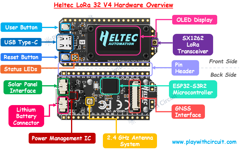
ESP32-S3R2 Microcontroller At the core of the board is the ESP32-S3 microcontroller, which acts as the main processing unit of the entire system. The ESP32-S3 is a dual-core processor capable of operating up to 240 MHz and includes integrated Wi-Fi and Bluetooth support.
SX1262 LoRa Transceiver The SX1262 is the dedicated LoRa communication chip integrated on the board. This component is responsible for all long-range wireless communication functions.
OLED Display The board includes a 0.96-inch OLED display mounted on the front side of the PCB. This display is internally connected to the ESP32 using the I2C communication interface and is mainly used for displaying system information, sensor values, debugging messages, communication status, and user interface elements.
USB Type-C Interface The USB Type-C connector is used for power input, firmware uploading, and serial communication between the board and a computer.
User Button The user button is connected to the ESP32 and is mainly used for boot mode selection and user interaction. During firmware uploading, this button may be used to place the ESP32 into programming mode.
Reset Button The Reset button restarts the ESP32-S3 microcontroller and reloads the firmware currently stored in memory.
Power Management IC The Power Management IC manages power distribution, battery charging, voltage regulation, and source switching between USB power, battery input, and solar input. The power-management subsystem ensures stable operation while protecting the board from voltage instability and charging-related issues.
Lithium Battery Connector The board includes a dedicated lithium battery connector that allows direct connection of single-cell Li-ion or LiPo batteries. This connector interfaces directly with the onboard charging and power-management circuitry.
Solar Panel Interface A dedicated solar-panel connector is included on the V4 board. This interface allows compatible solar panels to provide input power for charging the connected lithium battery and operating the system simultaneously.
GNSS Interface The GNSS interface is an 8-pin expansion connector designed for connecting external GPS or GNSS receiver modules. The board itself does not contain a GPS chip, but this connector exposes dedicated UART communication lines and control signals for simplified GNSS integration. The interface includes TX, RX, PPS timing, reset, and wake-up signals that allow the ESP32 to communicate directly with compatible GNSS modules without requiring complicated external wiring.
2.4 GHz Antenna System The board includes an integrated 2.4 GHz antenna system used for Wi-Fi and Bluetooth communication. The antenna is designed to improve wireless signal stability and communication reliability while maintaining a compact form factor. Compared to earlier antenna designs used in older boards, the V4 version uses a more optimized antenna structure for better RF performance and communication consistency.
LoRa Antenna Connector The dedicated LoRa antenna connector provides the RF interface for the SX1262 transceiver. This connector is used to attach an external LoRa antenna optimized for the selected operating frequency band. The antenna plays a critical role in transmission efficiency, signal strength, and communication range. Proper antenna selection significantly affects the overall performance of LoRa communication.
GPIO Pin Headers The dual-row pin headers located along the edges of the board expose the GPIO pins of the ESP32-S3 microcontroller. These headers provide access to digital I/O, analog inputs, UART, SPI, I2C, PWM, ADC, and touch-sensing functionality. External sensors, displays, communication modules, and actuators can be connected through these headers.
Status LEDs The board includes onboard LEDs used for power indication, status feedback, and debugging purposes. These LEDs help indicate board activity during power-up, firmware execution, uploading, and communication operations. In some applications, they may also be controlled directly through software for custom indication purposes.
Pinout Configuration
The Heltec WiFi LoRa 32 V4 exposes most of the ESP32-S3 GPIOs through two 18-pin headers labeled J2 and J3. These pins provide access to digital GPIO, analog inputs, communication interfaces, touch sensing, power control, and several onboard peripheral connections.
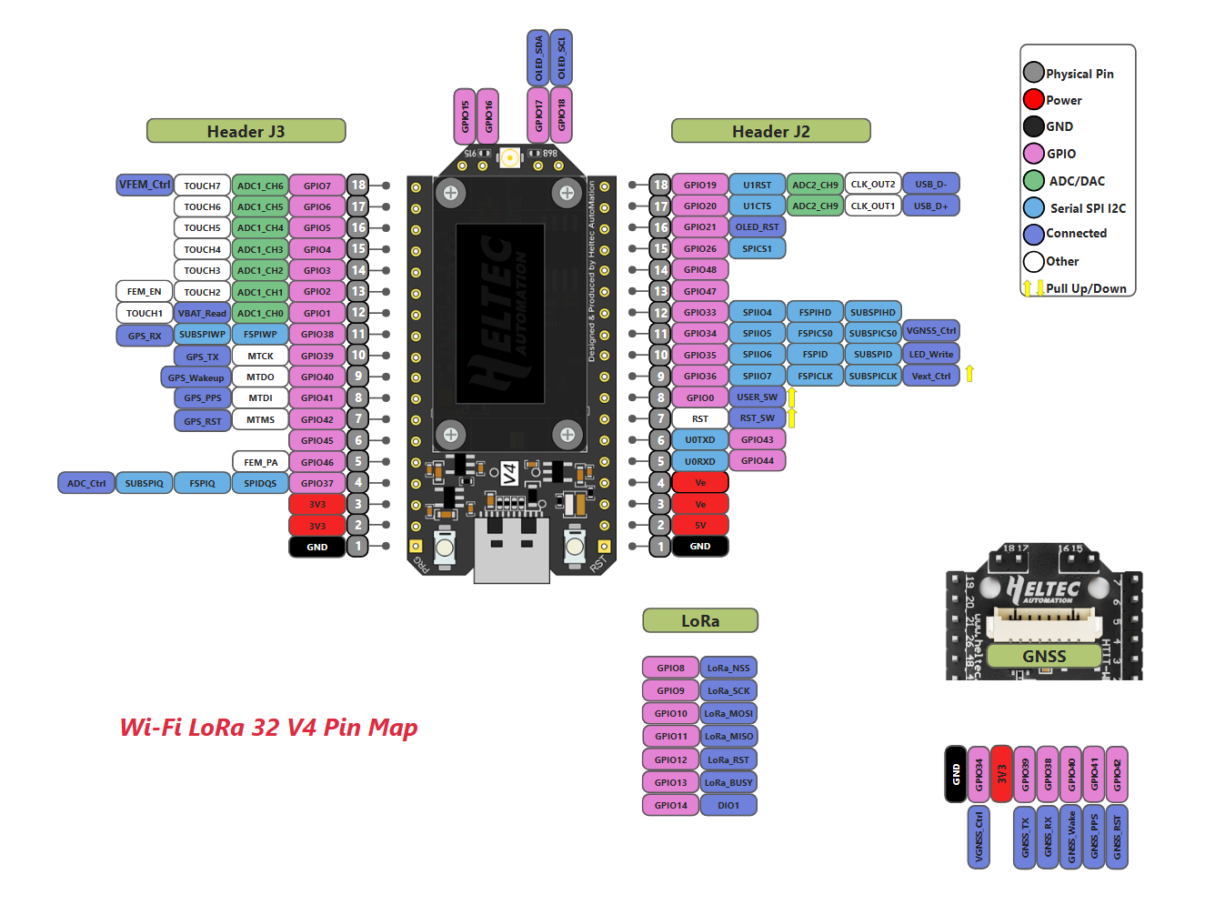
Power Pins
The board includes multiple power pins for powering the board and external peripherals.
| Pin | Function |
|---|---|
| 5V | Main USB power input/output |
| 3V3 | Regulated 3.3V output |
| GND | Ground reference |
| Ve | External power output |
The 5V pin is connected to the USB Type-C input and can be used to power the board externally. The 3.3V pin provides regulated voltage from the onboard voltage regulator and is commonly used for sensors and low-power peripherals.
Ve pins provide controlled external 3.3V output. These pins are managed through the Vext_Ctrl signal connected to GPIO36. This allows the ESP32-S3 to enable or disable power delivery to external peripherals programmatically, which is especially useful in low-power battery-operated applications.
GPIO pins
The GPIO pins are general-purpose digital input/output pins connected directly to the ESP32-S3 microcontroller. These pins can function as digital inputs, digital outputs, PWM outputs, interrupts, or communication interfaces depending on firmware configuration. Because the ESP32-S3 supports GPIO Matrix and IO MUX functionality, most GPIOs can be dynamically reassigned for interfaces such as SPI, UART, I2C, PWM, and I2S.
Some GPIOs are completely free, while others are internally connected to onboard peripherals such as LoRa transceiver, OLED display, USB subsystem, GNSS connector, battery monitoring circuitry. Reassigning these pins may affect the original onboard functionality.
UART Pins
The primary UART interface uses:
- GPIO43 → UART TX
- GPIO44 → UART RX
These pins are internally connected to UART0 peripheral can be used for: GNSS module communication, firmware uploading, serial debugging and Arduino Serial Monitor communication.
Because the ESP32-S3 supports multiple UART controllers, additional UART interfaces can also be mapped to other GPIOs if required.
USB Pins
The V4 board uses native USB support provided directly by the ESP32-S3 instead of an external USB-to-serial chip.
The USB interface uses:
- GPIO20 → USB_D+
- GPIO19 → USB_D-
These pins are permanently connected to the USB subsystem and should generally not be reused for other applications. Native USB support allows:
- faster uploads,
- integrated serial communication, to use this USB port for serial communication then USB CDC On Boot must be enabled.
- lower hardware complexity.
OLED display Pins
The onboard 0.96-inch OLED display uses the I2C communication interface and is internally connected to:
- GPIO17 → OLED SDA
- GPIO18 → OLED SCL
- GPIO21 → OLED RST
Since these pins are already occupied by the display hardware, they should generally not be reused for unrelated external peripherals unless the OLED is disabled in firmware.
Lora SPI Pins
The SX1262 LoRa transceiver communicates with the ESP32-S3 using an SPI interface. The dedicated LoRa pins are:
| GPIO | Function |
|---|---|
| GPIO8 | LoRa NSS |
| GPIO9 | LoRa SCK |
| GPIO10 | LoRa MOSI |
| GPIO11 | LoRa MISO |
| GPIO12 | LoRa Reset |
| GPIO13 | LoRa Busy |
| GPIO14 | DIO1 |
These pins are permanently connected to the SX1262 radio transceiver and are critical for LoRa communication. Modifying or reusing these pins may disrupt wireless operation.
GNSS Interface Pins
One of the important additions in the V4 board is the dedicated GNSS connector interface. The GNSS subsystem exposes multiple UART and control signals through dedicated GPIOs.
| GPIO | GNSS Function |
|---|---|
| GPIO38 | GNSS_RX |
| GPIO39 | GNSS_TX |
| GPIO40 | GNSS_Wakeup |
| GPIO41 | GNSS_PPS |
| GPIO42 | GNSS_RST |
The board does not include an onboard GPS receiver. Instead, these pins provide a simplified interface for connecting external GNSS modules directly through UART communication.
ADC and Analog Pins
Several GPIOs support analog-to-digital conversion through the ESP32-S3 ADC subsystem.
ADC-capable pins include:
- GPIO1 to GPIO7
- GPIO19
- GPIO20
GPIO1 is additionally connected to the battery-voltage sensing circuitry. The board uses ADC1_CH0 together with GPIO37 (ADC_Ctrl) for monitoring lithium battery voltage. This allows the ESP32 to monitor battery level directly through firmware without requiring external circuitry.
To use GPIO 1 pin to measure battery voltage then 3.7v li-ion or li-po battery should be connected at connector JP2(BAT) and ADC_Ctrl pin should be HIGH.
Touch Sensor Pins
The ESP32-S3 supports capacitive touch sensing on multiple GPIOs. On the Heltec V4, touch functionality is available on GPIO1 to GPIO7. These pins can detect touch interaction without mechanical buttons and are useful for: touch interfaces, gesture control and low-power input systems.
Note that several pins on the Heltec V4 are reserved for onboard peripherals and power-management functions. Reusing these pins without understanding their internal purpose may interfere with wireless communication, OLED operation, USB functionality, or analog measurements. Therefore, before designing any project, it is important to identify which pins are free for external use and which pins are internally occupied by onboard hardware.
Installing Arduino IDE
First we install the latest version of the Arduino IDE. Since the Heltec WiFi LoRa 32 V4 is based on the ESP32-S3 microcontroller, using the latest Arduino IDE version is recommended because newer versions include better support for ESP32-S3 development boards.
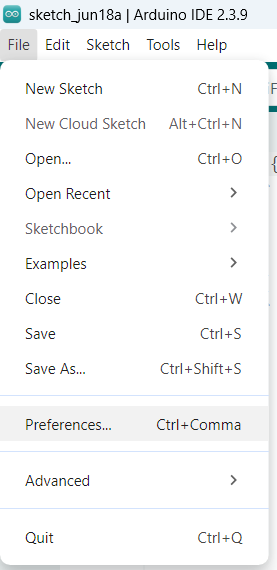
After installing Arduino IDE, launch the application and open the Preferences menu from:
File → Preferences
Inside the Preferences window, locate the field called: Additional Board Manager URLs.
This field allows Arduino IDE to download additional board packages from external sources. Heltec provides its own ESP32 framework package.
Now, add the following URL into the Board Manager field:
https://resource.heltec.cn/download/package_heltec_esp32_index.json
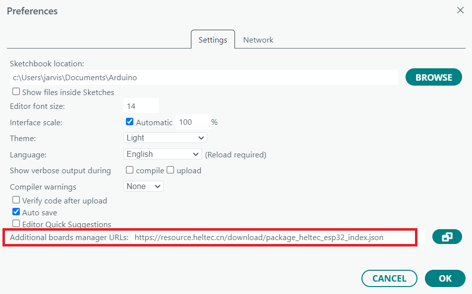
If you already have other URLs added, simply place this one on a new line.
After adding the URL, click OK to save the settings.
Without this package, the Arduino IDE will not properly recognize the Heltec WiFi LoRa 32 V4.
Installing the Heltec ESP32 Framework
Once the Board Manager URL is configured, the next step is installing the Heltec ESP32 framework.
Open Boards Manager and in the search bar, type: Heltec ESP32
You should see the Heltec ESP32 package appear in the search results. Install the latest available version.
This framework is extremely important because it contains:
- ESP32-S3 support
- Board configuration files
- USB configuration
- LoRa hardware mappings
- OLED initialization support
Unlike standard ESP32 boards, the Heltec V4 depends heavily on this framework because many hardware components are already preconfigured inside it. After installation completes, restart Arduino IDE.
Installing the Heltec ESP32 Library
The framework alone is not enough to start developing LoRa applications. We also need the Heltec ESP32 library, which provides:
- LoRa examples
- OLED examples
- Board helper functions
- Communication utilities
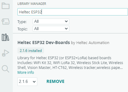
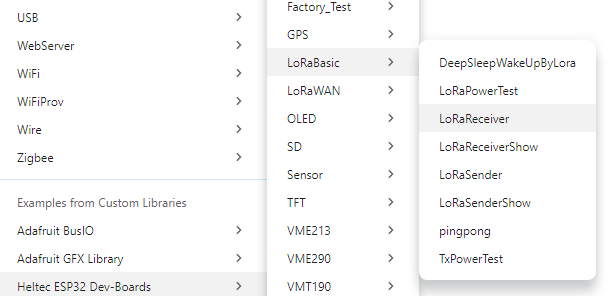
To install the library, Open Manage Libraries. Search for: Heltec ESP32 Dev-Boards.
You may see multiple libraries created by other users. Make sure you install the official Heltec version as shown below.
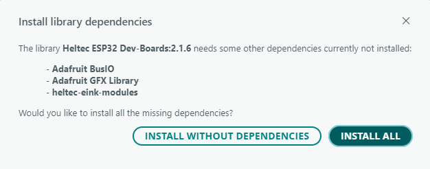
Arduino IDE may ask whether you want to install additional dependencies. Accept all dependencies because the LoRa and OLED examples require multiple supporting libraries.
Understanding the Heltec V4 Board Detection Problem
One of the most common problems users encounter is that the Arduino IDE shows: Heltec V2 board and V3 board but the V4 board may not appear. This usually happens because the installed package index is outdated. In some cases, the Arduino Board Manager may install an older Heltec framework version that does not yet include V4 definitions. This issue confuses many beginners because the framework appears installed correctly but the board still does not show up.
So the solution is manually updating the framework from GitHub.
For updating the framework visit the official Heltec GitHub repository:
https://github.com/HelTecAutomation/Heltec_ESP32
Open the Releases section and download the latest framework ZIP file. After downloading:
- Extract the ZIP archive
- Locate the Arduino packages directory on your system
The framework is typically installed inside the Arduino packages folder.
Inside this folder you will find:
- Hardware definitions
- ESP32 board files
- Toolchains
Replace the older framework version with the newer extracted version. After restarting Arduino IDE, the Heltec WiFi LoRa 32 V4 should now appear in the board selection menu.
Selecting the Correct Board
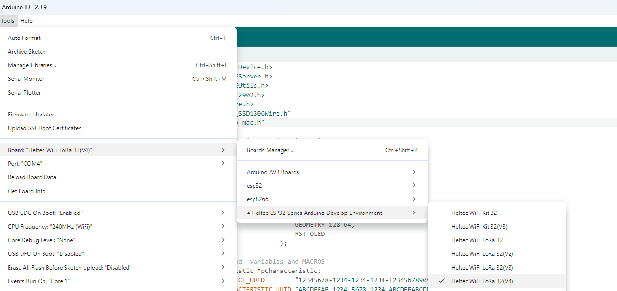
Now open: Tools → Board
Select: Heltec WiFi LoRa 32 V4
Then connect the board using a USB-C cable
Understanding Native USB on the V4 Board
One of the biggest changes in the Heltec V4 is the removal of the CP2102 USB-to-serial chip. Older boards used an external serial converter. The V4 instead uses native USB support of the ESP32-S3.
This has several advantages:
- Lower hardware complexity
- Lower power consumption
- Faster communication
- Better integration
However, it also introduces one important configuration requirement.
Enabling USB CDC on Boot
After uploading your first sketch, you may notice that upload succeeds but Serial Monitor shows nothing. This is one of the most common issues with the V4 board.
The reason is that native USB serial communication is disabled by default.
To fix this, open: Tools → USB CDC On Boot
Set it to: Enabled
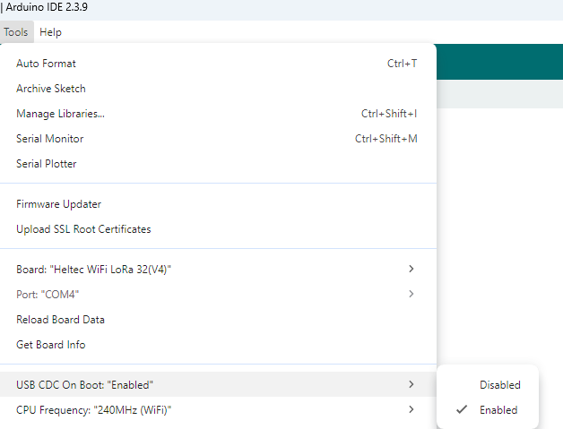
This setting enables USB serial communication during boot.
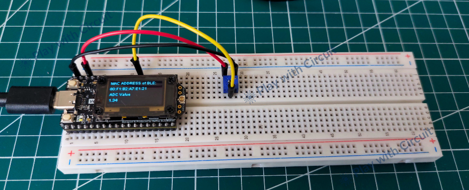
Uploading Your First Program
To verify that the Heltec framework and board are configured correctly, let’s upload a simple test sketch. In this example, Bluetooth Low Energy (BLE) is initialized in read/write and notify mode. The analog voltage is continuously read from the ADC pin and the measured value is displayed on the onboard OLED display. At the same time, the ADC data is transmitted wirelessly over BLE, allowing it to be monitored on a smartphone using applications LightBlue BLE.
Hardware Requirement
Software Requirement
- Arduino IDE latest revision
- Heltec ESP32 Series board support package, by Heltec Automation, latest version
- Heltec ESP32 Dev-Boards Library, by Heltec Automation, latest version
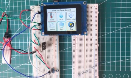
Circuit Diagram
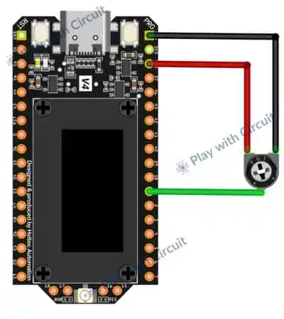
In the above circuit diagram middle pin of 10k-ohm pot has been connected to GPIO 1 of the board. The other two pins are connected to 3v3 supply pin and Gnd pin.
Code
This sketch reads an analog voltage, displays the measured value on the OLED, and wirelessly transmits the data to a smartphone using BLE notifications.
#include <BLEDevice.h>
#include <BLEServer.h>
#include <BLEUtils.h>
#include <BLE2902.h>
#include <Wire.h>
#include "HT_SSD1306Wire.h"
#include "esp_mac.h"

// define ADC pin to read analog values
#define ADC_PIN 1

// create object for the OLED display
static SSD1306Wire display(
                            0x3c,
                            500000,
                            SDA_OLED,
                            SCL_OLED,
                            GEOMETRY_128_64,
                            RST_OLED
                        );

// BLE related  variables and MACROS
BLECharacteristic *pCharacteristic;
#define SERVICE_UUID        "12345678-1234-1234-1234-1234567890AB"
#define CHARACTERISTIC_UUID "ABCDEFAB-1234-5678-1234-ABCDEFABCDEF"

void setup()
{
    uint8_t bt_mac[6];
    char macStr[18];

    // Read MAC address of BLE
    esp_read_mac(bt_mac, ESP_MAC_BT);
    sprintf(macStr, "%02X:%02X:%02X:%02X:%02X:%02X", bt_mac[0], bt_mac[1], bt_mac[2], bt_mac[3], bt_mac[4], bt_mac[5]);

    // enable the power for the OLED
    pinMode(36, OUTPUT);
    digitalWrite(36, LOW);
    delay(100);

    // initialize OLED display
    display.init();
    display.clear();

    // start serial UART
    Serial.begin(9600);

    // configure ADC, setting resolution to 12 so that counts can vary from 0 to 4095 and from 0 to 3.3v change in volt
    analogReadResolution(12);
    analogSetPinAttenuation(ADC_PIN, ADC_11db);

    // initialize BLE stack, the string provided will be shown as BLE device name
    BLEDevice::init("Heltec_V4_BLE");

    // create BLE server, now phone will act as client
    BLEServer *pServer = BLEDevice::createServer();

    // create BLE service
    BLEService *pService = pServer->createService(SERVICE_UUID);

    // create characteristic, and set properties like read, write and notify
    pCharacteristic = pService->createCharacteristic(
                                                        CHARACTERISTIC_UUID,
                                                        BLECharacteristic::PROPERTY_READ  |
                                                        BLECharacteristic::PROPERTY_WRITE |
                                                        BLECharacteristic::PROPERTY_NOTIFY
                                                    );

    // Allows phone to enable notifications
    pCharacteristic->addDescriptor(new BLE2902());

    // Default characteristic value
    pCharacteristic->setValue("Hello from Heltec ESP32");

    // register service
    pService->start();

    // Get advertising object
    BLEAdvertising *pAdvertising = BLEDevice::getAdvertising();

    // Starts BLE beacon, now phone can discover our BLE device
    pAdvertising->start();

    Serial.println("BLE Advertising Started");
  display.setFont(ArialMT_Plain_10);
    display.drawString(0, 0, "MAC ADDRESS of BLE:");
    display.drawString(0, 15, macStr);
    display.drawString(0,30,"ADC Value");
    display.display();
}

void loop()
{
    static float adcValue;

    adcValue = (analogRead(ADC_PIN)*3.3)/4096;
    String msg = "Adc value = " + String(adcValue);

    pCharacteristic->setValue(msg.c_str());
    pCharacteristic->notify();

    Serial.println(msg);
    display.setColor(BLACK);
    display.fillRect(0,45,128,20);
    display.setColor(WHITE);
    display.drawString(0,45,String(adcValue));

    display.display();
    delay(300);
}
Code Explanation
Including Libraries & Defining the ADC Pin
We begin by including all the required libraries. First, we include the BLE libraries to create a Bluetooth Low Energy server and exchange data with a smartphone or another BLE device. The Wire library provides I2C communication support, which allows the ESP32-S3 to communicate with the onboard OLED display. We include the HT_SSD1306Wire library specifically for controlling the Heltec OLED display, while the esp_mac.h header gives us access to the ESP32 MAC address functions.
Then, we define GPIO1 as the analog input pin used for reading voltage values.
#include <BLEDevice.h>
#include <BLEServer.h>
#include <BLEUtils.h>
#include <BLE2902.h>
#include <Wire.h>
#include "HT_SSD1306Wire.h"
#include "esp_mac.h"
// define ADC pin to read analog values
#define ADC_PIN 1
Creating the OLED Display Object
Here, we create an object for the SSD1306 OLED display. We configure the I2C address, communication speed, display geometry, and the corresponding SDA, SCL, and reset pins. Once this object is created, we can easily send text and graphics to the OLED screen using the functions provided by the library.
// create object for the OLED display
static SSD1306Wire display(
                            0x3c,
                            500000,
                            SDA_OLED,
                            SCL_OLED,
                            GEOMETRY_128_64,
                            RST_OLED
                        );
Defining BLE Variables and UUIDs
Next, we create a pointer for the BLE characteristic object and define unique identifiers for the BLE service and characteristic. In BLE communication, services and characteristics act like containers that organize and exchange data. The service groups related information, while the characteristic represents the actual data that the client device can read, write, or receive through notifications.
// BLE related  variables and MACROS
BLECharacteristic *pCharacteristic;
#define SERVICE_UUID        "12345678-1234-1234-1234-1234567890AB"
#define CHARACTERISTIC_UUID "ABCDEFAB-1234-5678-1234-ABCDEFABCDEF"
Reading the Bluetooth MAC Address
At the beginning of the setup function, we read the Bluetooth MAC address of the ESP32-S3. The MAC address uniquely identifies the BLE interface and can be useful for debugging or device identification. We then convert the six-byte hexadecimal address into a human-readable string format so that it can be displayed on the OLED screen.
void setup()
{
    uint8_t bt_mac[6];
    char macStr[18];

    // Read MAC address of BLE
    esp_read_mac(bt_mac, ESP_MAC_BT);
    sprintf(macStr, "%02X:%02X:%02X:%02X:%02X:%02X", bt_mac[0], bt_mac[1], bt_mac[2], bt_mac[3], bt_mac[4], bt_mac[5]);
Initializing the OLED Display
Before initializing the OLED, we first enable its power supply. GPIO36 controls the external power rail on the Heltec V4 board. Pulling this pin LOW activates the Vext output, which supplies power to the OLED module. We then wait briefly to ensure the display receives stable power before continuing.
We initialize the OLED display and clear any previous content stored in its memory.
  // enable the power for the OLED
    pinMode(36, OUTPUT);
    digitalWrite(36, LOW);
    delay(100);

    // initialize OLED display
    display.init();
    display.clear();
Configuring the ADC
Next, we initialize UART serial communication at a baud rate of 9600 bits per second.
Then, we configure the analog-to-digital converter to use a 12-bit resolution. This means the ADC output can vary between 0 and 4095, providing good measurement accuracy. We also set the attenuation to 11 dB, which expands the measurable voltage range and allows the ESP32 to handle voltages close to 3.3 V. This configuration ensures that the analog sensor values are converted into digital values with sufficient precision.
   // start serial UART
    Serial.begin(9600);

    // configure ADC, setting resolution to 12 so that counts can vary from 0 to 4095 and from 0 to 3.3v change in volt
    analogReadResolution(12);
    analogSetPinAttenuation(ADC_PIN, ADC_11db);
Initializing BLE and Creating the BLE Server
We initialize the Bluetooth Low Energy stack and assign the device name “Heltec_V4_BLE”. This name becomes visible when nearby devices scan for BLE peripherals.
Here, we create the BLE server object. In this communication, the ESP32 acts as the server, while a smartphone or another BLE device behaves as the client. The server waits for incoming connections and provides data to connected devices.
We create a BLE service using the previously defined UUID. The service acts as a container that organizes related characteristics. It helps the client understand what kind of information the device provides.
Next, we create a characteristic inside the service and assign three properties: Read, Write and Notify. These properties allow the client to read data, send data to the ESP32, and receive automatic notifications whenever new values become available.
  // initialize BLE stack, the string provided will be shown as BLE device name
    BLEDevice::init("Heltec_V4_BLE");

    // create BLE server, now phone will act as client
    BLEServer *pServer = BLEDevice::createServer();

    // create BLE service
    BLEService *pService = pServer->createService(SERVICE_UUID);

    // create characteristic, and set properties like read, write and notify
    pCharacteristic = pService->createCharacteristic(
                                                        CHARACTERISTIC_UUID,
                                                        BLECharacteristic::PROPERTY_READ  |
                                                        BLECharacteristic::PROPERTY_WRITE |
                                                        BLECharacteristic::PROPERTY_NOTIFY
Enabling Notifications
We add a BLE2902 descriptor to enable notifications. Without this descriptor, most smartphone applications cannot subscribe to characteristic updates. This step allows the client device to receive new values automatically without repeatedly polling the server.
We assign an initial text value to the characteristic. This value becomes available immediately after the client connects to the BLE server.
Once the characteristic has been configured, we start the BLE service. This makes the service available to connected clients.
We obtain the advertising object and start BLE advertising. Advertising broadcasts the device’s presence so that nearby smartphones or BLE scanners can discover and connect to it.
From this point onward, the ESP32 behaves like a BLE beacon waiting for client connections.
We configure the display font and print the BLE MAC address along with a label for the ADC value. Finally, we call display.display() to transfer the contents of the display buffer onto the OLED screen.
  // Allows phone to enable notifications
    pCharacteristic->addDescriptor(new BLE2902());

    // Default characteristic value
    pCharacteristic->setValue("Hello from Heltec ESP32");

    // register service
    pService->start();

    // Get advertising object
    BLEAdvertising *pAdvertising = BLEDevice::getAdvertising();

    // Starts BLE beacon, now phone can discover our BLE device
    pAdvertising->start();

    Serial.println("BLE Advertising Started");
    display.setFont(ArialMT_Plain_10);
    display.drawString(0, 0, "MAC ADDRESS of BLE:");
    display.drawString(0, 15, macStr);
    display.drawString(0,30,"ADC Value");
    display.display();
}
Loop Function
Inside the loop function, we continuously read the analog value from GPIO1. Since the ADC returns a digital number between 0 and 4095, we convert that reading into an equivalent voltage by scaling it with the reference voltage of 3.3 V. Logically, this step converts raw ADC counts into a meaningful voltage value.
We combine the measured voltage with a text label to create a complete message string. This string will later be transmitted through BLE and printed on the Serial Monitor.
We update the BLE characteristic with the latest ADC value and then notify connected devices. As a result, smartphones or BLE clients receive the new voltage reading automatically without requesting it manually.
We print the same message to the Serial Monitor for debugging purposes. We first erase the previous ADC value by drawing a black rectangle over that region. Then we switch back to white color and display the latest voltage value. Finally, we refresh the OLED screen so that the new reading becomes visible. This updates only a portion of the screen instead of redrawing everything, which improves display performance.
Finally, we pause the program for 300 milliseconds before repeating the loop. This delay controls the update rate and prevents the BLE notifications, Serial Monitor messages, and OLED refresh operations from occurring too rapidly.
void loop()
{
    static float adcValue;

    adcValue = (analogRead(ADC_PIN)*3.3)/4096;
    String msg = "Adc value = " + String(adcValue);

    pCharacteristic->setValue(msg.c_str());
    pCharacteristic->notify();

    Serial.println(msg);
    display.setColor(BLACK);
    display.fillRect(0,45,128,20);
    display.setColor(WHITE);
    display.drawString(0,45,String(adcValue));

    display.display();
    delay(300);
}
Video Demonstration
The following video shows the output of the code running on the Heltec WiFi LoRa 32 V4. First, we install and open the LightBlue BLE application on a smartphone and then observe the change in ADC values when we rotate the Pot.
More Examples
Running the LoRa Sender Example
Now that the setup is complete, you can test LoRa communication.
Open: File → Examples → Heltec ESP32 Dev-Boards → LoRa → LoRaSender
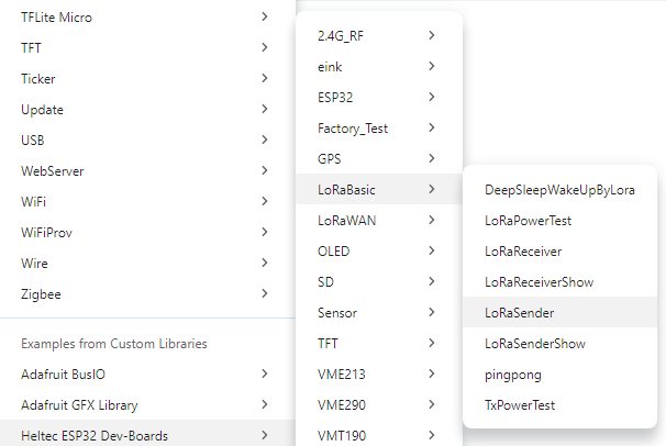
This example continuously transmits packets over LoRa.
Before uploading set the correct frequency for your region. For example:
- 868 MHz → Europe/India
- 915 MHz → USA
Modify the transmitted message if desired. Upload the sketch.
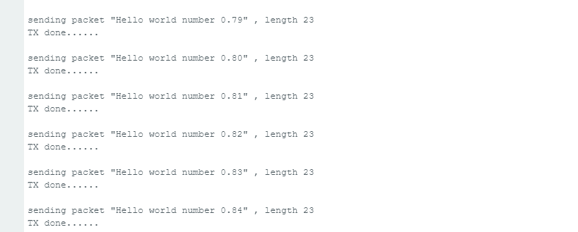
The Serial Monitor should now show packets being transmitted periodically.
Running the LoRa Receiver Example
To receive data open the LoRaReceiver example and upload it to another Heltec board.
Once running the receiver enters RX mode and incoming packets appear in Serial Monitor. You should now see: received packet, RSSI values and LoRa packet length.
This confirms LoRa hardware works, framework setup is correct and Radio communication is working.
Troubleshooting Heltec WiFi LoRa 32 V4 Board
Issue 1: Board Not Detected by Computer
Use a USB data cable and reconnect the board. Make sure the correct COM port appears in Arduino IDE. If the board still doesn’t appear, try another USB port or cable.
Issue 2: Device Continuously Resets
Use a stable 5V source and a high-quality USB cable. If using a battery, ensure its voltage is within the supported range.
Issue 3: Upload Failed or Stuck at Connecting
- Hold the BOOT (PRG) button.
- Press the RESET button.
- Start uploading the sketch.
- Release the BOOT button when uploading begins.
This forces the ESP32-S3 into download mode.
Issue 4: Heltec WiFi LoRa 32 V4 Does Not Appear in Arduino IDE
Update the Heltec ESP32 package or manually install the latest framework from the official Heltec GitHub repository.
Issue 5: LoRa Communication Is Not Working
Verify that both devices use the same LoRa frequency, such as: 433 MHz, 868 MHz and 915 MHz
The frequency must match on both boards.
Issue 6: No Packets Are Received
Check: Frequency, Spreading factor, Bandwidth and Coding rate. Both transmitter and receiver should use identical settings.
Issue 7: Antenna Is Not Connected
Always connect an antenna before enabling LoRa transmission. Operating the SX1262 without an antenna may damage the RF output stage. If an antenna is unavailable, connect a 50Ω dummy load.
Issue 8: Board Gets Hot During Operation
Disconnect external peripherals and check the wiring carefully. Inspect for short circuits before powering the board again.
FAQ’S
Is the Heltec WiFi LoRa 32 V4 suitable for beginners?
Yes, the Heltec WiFi LoRa 32 V4 is beginner-friendly, but it requires some initial setup. Once the Heltec framework and Arduino IDE are configured properly, developers can quickly start building LoRa, Wi-Fi, Bluetooth, and sensor-based projects using the provided examples.
Does the Heltec WiFi LoRa 32 V4 have built-in GPS?
No, the board does not include an onboard GPS receiver. However, it provides a dedicated 8-pin GNSS connector that allows easy integration with external GPS or GNSS modules through UART communication.
What is the difference between Heltec LoRa 32 V3 and V4?
The V4 version introduces several improvements over the V3, including:
- ESP32-S3R2 microcontroller
- 16 MB Flash and 2 MB PSRAM
- Native USB support
- Improved power management
- Solar panel connector
- Dedicated GNSS interface
- Higher LoRa transmit power
- Better antenna design and display protection
What is the communication range of the Heltec WiFi LoRa 32 V4?
The communication range depends on antenna quality, environment, and LoRa settings. In open areas, several kilometers of range are achievable, while in urban environments the range is typically reduced due to buildings and interference.
Does the Heltec WiFi LoRa 32 V4 support deep sleep?
Yes. The board supports deep sleep and low-power modes. Combined with battery and solar support, this makes it suitable for long-term remote deployments.
Can I use the Heltec V4 with Meshtastic?
Yes. The board is fully compatible with Meshtastic firmware and is widely used for creating long-range mesh communication networks.
