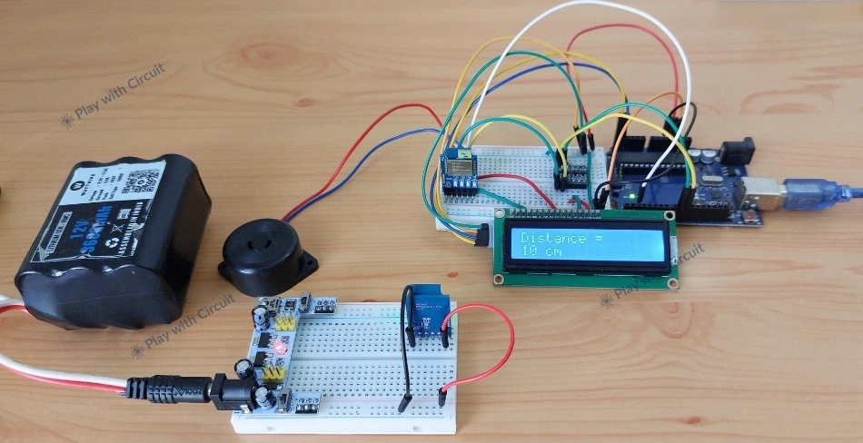
Imagine placing a device on a bag, a tool, or another object and getting an alert when it moves beyond a certain distance. This kind of distance-based monitoring can be useful in many practical situations such as equipment monitoring, indoor positioning, secure access, and real-time tracking of objects in factories and warehouses.
While technologies such as Bluetooth, Wi-Fi, and other wireless technologies can be used for proximity detection, their distance estimates can change when the signal encounters obstacles, passes through walls, or reflects off surrounding objects.
This is where UWB becomes useful. UWB can measure the time taken for a radio signal to travel between two devices, allowing much more precise distance measurement. Its very short-duration signals and wide bandwidth provide fine time resolution, allowing UWB devices to determine the distance between them with high precision.
In this project, we’ll build a simple Object Distance Monitoring and Alert System using Arduino and two REYAX RYUW122_Lite UWB modules. One module will act as a fixed Anchor, while the other will work as a Tag attached to the object we want to monitor. Arduino will display the measured distance on an LCD and continuously compare it with a predefined distance. If the object moves beyond the defined distance limit, a buzzer is activated to alert the user.
How does this UWB Distance Monitoring System Work?
The system consists of two RYUW122_Lite UWB modules. One module is configured as an Anchor and another one as Tag. The Anchor is connected to the Arduino UNO, while the Tag is attached to the object whose distance needs to be monitored.
When the Arduino sends a distance measurement command to the Anchor, the Anchor communicates with the Tag and returns the measured distance through its UART interface. This distance is displayed on a 16×2 I2C LCD in centimeters. Meanwhile, the Arduino compares the measured distance with a preset limit of 200 cm. If the distance exceeds this limit, the buzzer sounds to alert the user.
This way, the system monitors the distance between the Anchor and the Tag and provides distance reading and an alert when the object moves beyond the defined limit.
What is Ultra Wideband (UWB) Technology?
Ultra Wideband (UWB) is a short-range wireless communication technology used for highly accurate ranging, positioning, and secure data exchange. It operates by transmitting very short radio pulses across a wide frequency spectrum.
Unlike traditional wireless technologies such as Bluetooth® Low Energy (BLE) and Wi-Fi, which estimate distance based on the strength of the received signal (RSSI), UWB measures the Time of Flight (ToF) of radio signals. This allows it to determine the distance between two devices with centimeter-level accuracy.
One of the main advantages of UWB is its ability to perform precise distance measurement without relying mainly on received signal strength. Signal-strength-based proximity detection can be affected by walls, objects, people, reflections, and the orientation of the devices. UWB instead uses the timing of the transmitted signal, making it well suited for applications where knowing the actual distance between devices is important.
How Does UWB Measure Distance?
The key to UWB distance measurement is Time of Flight (ToF). ToF is the time taken by a wireless signal to travel between two devices. Since radio signals travel at approximately the speed of light, even an extremely small measurement of travel time can be converted into a physical distance.
In a typical UWB ranging system, two devices exchange precisely timed wireless messages. The devices record when the messages are transmitted and received, and the system uses this timing information to determine how long the signal took to travel between them.
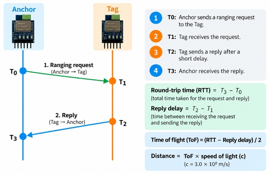
The distance can then be calculated from the propagation time of the radio signal. In simplified form:
Distance = Time of Flight × Speed of Light
For example, a radio signal takes only a few nanoseconds to travel a distance of around one meter. Measuring such a small time interval accurately is challenging, which is where UWB’s wide bandwidth becomes important. Its short-duration signals provide very fine timing resolution, allowing UWB hardware to distinguish very small differences in signal arrival time.
REYAX RYUW122_Lite Overview
The REYAX RYUW122_Lite is an Ultra-Wideband transceiver module. The module supports both Anchor and Tag operating modes, enabling accurate distance measurement between two devices while simultaneously transferring user data. Communication and configuration are performed entirely through AT commands, making the module easy to integrate with microcontrollers.
The RYUW122 provides location accuracy of approximately 10 cm under open-field conditions. It also includes AES-128 encryption to help secure wireless communication.
Features of REYAX RYUW122_Lite
- Supports IEEE 802.15.4-2015 UWB and IEEE 802.15.4z (BPRF mode)
- Supports UWB Channel 5 (6489.6 MHz) and UWB Channel 9 (7987.2 MHz)
- Up to 10 cm ranging accuracy (open-field conditions)
- Communication range up to 100 m (open field)
- UART interface with AT command control
- Integrated UWB antenna
- AES-128 encryption
- Supports both Anchor and Tag modes
- Configurable baud rates (default 115200 bps)
- Low-power sleep mode
- Operating voltage: 2.4–3.6 V
- Operating temperature: −40 °C to +85 °C
For more details refer to datasheet below:
REYAX RYUW122_Lite UWB Module Pinout
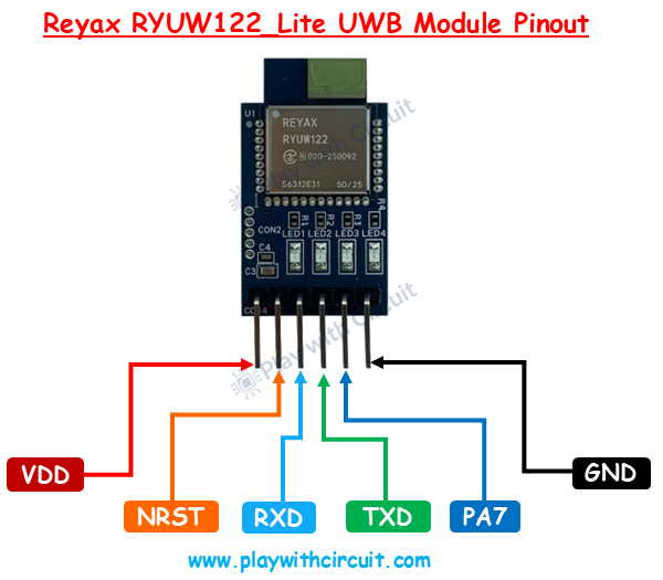
VDD The VDD pin is a power supply pin.
NRST Active-low hardware reset pin. Pulling this pin LOW resets and restarts the module.
RXD UART Receive pin. Receives AT commands and data from the host microcontroller.
TXD UART Transmit pin. Sends AT command responses, ranging data, and receives messages to the host microcontroller.
PA7 Mode indicator output. Outputs HIGH when the module is in Normal mode and LOW when it is in Sleep mode.
GND This is the ground pin.
Understanding Anchor and Tag
A UWB ranging system consists of two primary devices: an Anchor and a Tag. These devices work together to accurately measure the distance between them using Ultra-Wideband (UWB) signals. Before building the project, it is important to understand the role of each device.
What is an Anchor?
An Anchor is a stationary UWB device installed at a fixed and known location. It acts as the reference point in the system and communicates with one or more Tags to determine their distance. The Anchor calculates the distance based on the UWB signals exchanged with the Tag.
What is a Tag?
A Tag is a mobile UWB device attached to a person, vehicle, robot, or any object that needs to be detected. It communicates with the Anchor by exchanging UWB packets and can also transmit user data simultaneously. As the Tag moves, the distance between the Tag and the Anchor changes. The Anchor continuously measures this distance, allowing the system to monitor the Tag’s position relative to the fixed Anchor.
Configuring UWB Module as an Anchor and a Tag
To configure the RYUW122_Lite module as an Anchor or Tag, we first need to connect it to a PC or laptop using a USB-to-TTL converter. This allows us to communicate with the module through its UART interface and send AT commands using a serial monitor.
Connect the USB-to-TTL converter to the RYUW122_Lite as shown below.
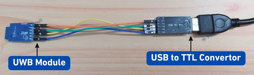
The VDD and GND connections provide power to the module, while the RXD and TXD pins are used for UART communication. Make sure that your USB-to-TTL converter uses a 3.3 V-compatible logic level before connecting it to the RYUW122_Lite. Using an incompatible voltage level on the UART pins can damage the module.
The connections are as follows:
| UWB Module Pin | USB to TTL module Pin |
|---|---|
| VDD (pin 1) | Connected to VDD/3v3 |
| Rxd (pin 3) | Connected to Txd |
| Txd (Pin 4) | Connected to Rxd |
| Gnd (Pin 6) | Connected to Gnd Pin |
Once the connections are made, open the Arduino IDE and start the Serial Monitor. Select the COM port assigned to the USB-to-TTL converter and set the baud rate to 115200. This is the default UART baud rate of the RYUW122_Lite. Also line ending should be set to “BOTH NL and CR” , it means when Enter is pressed on Keyboard ‘\n’ and ‘\r’ should be sent along with the command to be sent.

Before configuring the module, let’s first check whether the PC can communicate with it.
In the Serial Monitor,
SEND: AT and press Enter
If everything is connected and configured correctly, the module should respond with:
REPLY: +OK
This confirms that the module is responding to AT commands and is ready for further configuration.
Note: When Enter is pressed ‘\n’ and ‘\r’ is also sent to the Module after “AT”.
Commands for Configuring the UWB Modules
Once the RYUW122_Lite is connected to the PC through the USB-to-TTL converter, we can configure it using AT commands.
1. Factory Reset – AT+FACTORY
Reset both modules to their factory settings before starting the configuration. The AT+FACTORY command restores the module’s parameters to their default values.
Send the following command to both the Anchor and Tag: AT+FACTORY
The module should respond with: +FACTORY
If the module does not respond, first check the wiring and Serial Monitor settings. The UART baud rate may also have been changed previously. The module supports 9600, 57600, and 115200 baud, with 115200 as the default. Therefore, if you cannot communicate with a previously configured module, try the Serial Monitor at these baud rates.
2. Setting the Module Mode – AT+MODE
The AT+MODE command determines whether the module works as an Anchor or a Tag. The default mode is Tag mode.
For the Anchor, send: AT+MODE=1
For the Tag, send: AT+MODE=0
The module should respond with: +OK
You can also verify the current mode using: AT+MODE?
For example, a Tag will respond: +MODE=0
3. Setting the Network ID – AT+NETWORKID
The Network ID determines which UWB modules can communicate with each other. Both the Anchor and Tag must use the same Network ID. The Network ID must be less than or equal to 8-byte ASCII. By default it is Anchor12.
For this project, we can use: 1
Configure both Anchor and Tag modules with: AT+NETWORKID=1
The expected response is: +OK
To check the configured Network ID, send: AT+NETWORKID?
The module should respond: +NETWORKID=1
4. Setting the Module Address – AT+ADDRESS
Each UWB module needs its own unique address. The address must also be less than or equal to 8-byte ASCII value, so the Anchor and Tag should have different addresses.
For the Anchor, send: AT+ADDRESS=ANC
For the Tag, send: AT+ADDRESS=TAG
To check the configured address, send: AT+ADDRESS?
The Tag should respond: +ADDRESS=TAG
5. Setting the UART Baud Rate – AT+IPR
The AT+IPR command is used to change the UART baud rate of the RYUW122.
The module supports: 9600, 57600, 115200 with 115200 as the default.
For our project, we will configure the Anchor’s UART to 9600 baud: AT+IPR=9600
The module should respond: +OK
To verify the setting: AT+IPR?
The response should be: +IPR=9600
Make sure after you change baud-rate, send AT+IPR? command on new baud-rate (9600).
Here, we are using 9600 baud because the Anchor will be connected to an Arduino using a software-based serial interface. A lower baud rate is generally a more practical choice for reliable communication when using Arduino’s SoftwareSerial library.
Important: After changing the Anchor’s baud rate to 9600, configure the Serial Monitor to 9600 baud when communicating with that module from the PC. The baud-rate setting is for the module’s UART interface; it does not change the wireless UWB communication between the Anchor and Tag.
6. Sending Data from the Anchor to the Tag – AT+ANCHOR_SEND
The AT+ANCHOR_SEND command is particularly important for our project because the Anchor uses this command to communicate with the Tag and obtain the distance between them.
The command format is:
AT+ANCHOR_SEND=<TAG Address>,<Payload Length>,<Data>
The Tag address must be less than or equal to 8-byte ASCII value, the payload can contain a maximum of 12 bytes.
Since we configured our Tag address as TAG, the Anchor can send a simple message using:
AT+ANCHOR_SEND=TAG,2,Hi
The module first responds with: +OK
After successful communication, the Anchor generates a message containing the Tag address, received data, and calculated distance. For example: +ANCHOR_RCV=TAG,2,Hi,50 cm
The actual distance value will depend on the physical distance between the two modules. The module reports the distance between the Anchor and Tag in centimeters. In our project, the Arduino connected to the Anchor will read this response and extract the distance value.
Here are the images of serial communication for both Anchor and Tag.
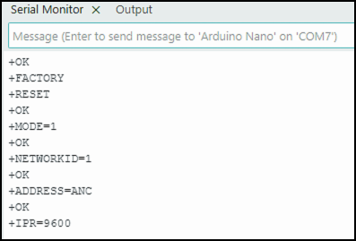
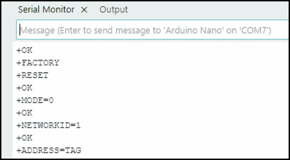
If you want to explore the other AT commands supported by the RYUW122_Lite, you can refer to the AT Command Guide provided below.
Building the UWB Distance Monitoring and Alert System
For this project, we use two RYUW122 UWB modules, with one configured as the Anchor and the other as the Tag. The Anchor is connected to the Arduino UNO which obtains the distance information from the Tag. Since the Arduino UNO has only one hardware serial port, we use a software-based serial interface to establish a separate UART connection between the Arduino and the Anchor UWB module. The Arduino continuously reads and parses the data received from the Anchor to obtain the measured distance. An I2C LCD is connected to the Arduino to display this distance, while a buzzer provides an alert when the distance between the Anchor and Tag exceeds the defined limit.
On the Anchor side, we will connect the RYUW122 module to the Arduino through the UART interface using the required voltage-level shifting, and connect the LCD and buzzer to the Arduino for distance display and alert indication. On the Tag side, no Arduino is required because the Tag only needs to be powered to participate in the UWB communication with the Anchor.
Hardware Requirement
| Component | Quantity | Description | Where to Buy |
|---|---|---|---|
| Arduino Uno R3 | 1 | One Arduino acts as the Anchor controller and the other as the Tag controller. | Amazon |
| REYAX RYUW122_Lite UWB Module | 2 | One module is configured as an Anchor and the other as a Tag for UWB ranging. | Amazon |
| I2C LCD Display | 1 | Displays the measured distance and system status. | Amazon |
| Breadboard | 2 | For making circuit connections. | Amazon |
| Jumper Wires | As required | Used to connect the Arduino, UWB module, and display. | Amazon |
| USB Cable A to B | 1 | Used to power and program both Arduino boards. | Amazon |
| Breadboard Power Supply Module | 1 | For powering Tag UWB Module | Amazon |
Software Requirement
- Arduino IDE, Version 2.3.9 or above installed on your PC.
- LiquidCrystal_I2C Library by Frank de Brabander V 1.1.2
Wiring RYUW122_Lite UWB Anchor Module with Arduino
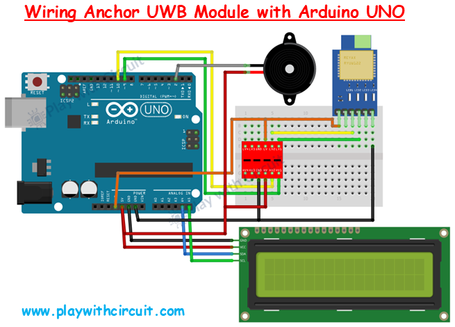
The RYUW122_Lite UWB module uses 3.3 V logic levels, whereas the Arduino UNO operates with 5 V logic levels. Because of this difference, we used a voltage level shifter between the Arduino and the Anchor UWB module. It safely translates the UART signal levels between the two devices.
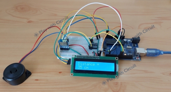
Now, let’s connect the TX pin of the Anchor RYUW122 module to the LV1 pin of the voltage level shifter. Then, connect the corresponding HV1 pin of the level shifter to Arduino pin 9. Then, connect Arduino pin 10 to the HV2 pin of the voltage level shifter, and connect the corresponding LV2 pin to the RX pin of the RYUW122 module.
Next we will connect the LCD. Connect SDA and SCL pins of the I2C LCD to the A4 and A5 pins of the Arduino UNO, respectively. Also connect the LCD’s power and GND connections to the Arduino supply and ground.
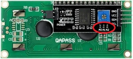
Before using the LCD, make sure the A0, A1, and A2 address-selection jumpers on the back of the I2C LCD are not shorted. In this configuration, the LCD uses the 0x27 I2C address.
Finally, connect the buzzer to digital pin 2 of the Arduino. Since the buzzer used in this circuit is Active LOW, it produces the alert when its control pin is driven LOW.
Here’s a quick table for the Anchor-side connections:
| Arduino Uno Pin | Peripherals |
|---|---|
| 3.3V | VDD of UWB module |
| GND | GND of UWB module |
| Pin 9 | Tx pin of UWB (via voltage shifter) |
| Pin 10 | Rx pin of UWB (via voltage shifter) |
| 5v | Vcc of I2C LCD |
| GND | GND of I2C LCD |
| A5 | SCL pin of I2C LCD |
| A4 | SDA pin of I2C LCD |
| Pin 2 | Gnd Pin of Buzzer |
| 5V Pin | Supply pin of Buzzer |
Here is the actual wired implementation of the Anchor-side circuit:
Wiring RYUW122_Lite UWB Tag Module with Power Supply
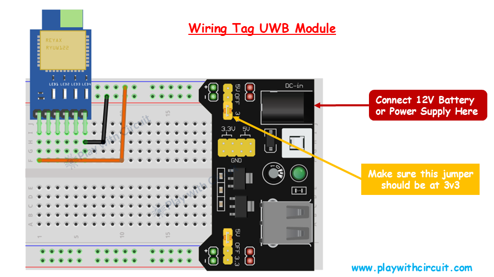
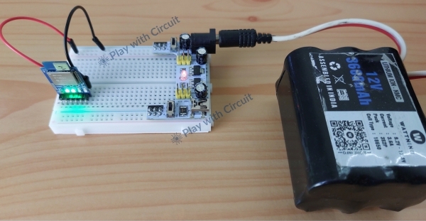
For the Tag, we only need to provide the required power. The wiring diagram uses a separate power-supply arrangement, where the 12 V battery or power supply is connected to the input of the power-supply module.
Make sure the jumper on the power-supply module is set to the 3.3 V position, as shown in the wiring diagram. Once powered, the Tag UWB module can participate in the UWB communication with the Anchor.
How the Tag and Anchor Work Together?
The Tag is attached to the object, while the Anchor remains at the monitoring location. The two RYUW122 modules communicate with each other using UWB, allowing the Anchor to obtain the distance to the Tag.
The Anchor then passes this distance information to the Arduino, which displays it on the LCD and controls the buzzer when the object moves beyond the specified limit.
Arduino Code
This Arduino sketch initializes the UWB module and continuously communicates with the Anchor to obtain the distance to the Tag. It then parses the received distance, displays it on the LCD, and activates the buzzer when the distance exceeds the defined limit.
/*
Code for distance measurement and Alert system using UWB technology and RYUW122 modules by www.playwithcircuit.com
*/
#include <Wire.h>
#include <SoftwareSerial.h>
#include <LiquidCrystal_I2C.h>

#define BUZZER_PIN 2

LiquidCrystal_I2C lcd(0x27, 16, 2);  // Format -> (Address,Width,Height )

//Create software serial object to communicate with UWB Module
SoftwareSerial UWB_Serial(9, 10);  // Now pin 9 and pin 10 of Arduino are Serial Rx & Tx pins respectively.

char serialInputArray[50];
int counter = 0;  // Counter for getting data from UWB module

const char cmd_array[] = "AT+ANCHOR_SEND=TAG,2,Hi";

bool boAlarm_flag = false;

unsigned int u32previoustick;
unsigned int u32previoustickBuzzer;
int buzzerpinvalue = 1;
// SETUP
void setup() {
 int retVal = 0;

 pinMode(BUZZER_PIN, OUTPUT);
 digitalWrite(BUZZER_PIN,buzzerpinvalue);
 // this serial port is to display error, if occurred during OLED init
 Serial.begin(9600);

 // initialize the lcd
 lcd.init();
 // Turn on the Backlight
 lcd.backlight();

 lcd.clear();
 lcd.setCursor(0, 0);
 lcd.print("Distance");
 lcd.setCursor(0, 1);
 lcd.print("Measuement");
 delay(2000);
 lcd.clear();
 lcd.setCursor(0, 0);
 lcd.print("Using REYAX");
 lcd.setCursor(0, 1);
 lcd.print("RYUW122 Modules");
 delay(2000);

 // Open the soft Serial port and set the data rate for the SoftwareSerial port at 115200 to communicate with UWB Module in Command Mode
 UWB_Serial.begin(9600);
 delay(100);
 // Send data to UWB Module
 UWB_Serial.print("AT");
 printCRLF_UWB();

 retVal = vCheck_OK();
 if (retVal == -1) {
   errorMsg();
   errorMsgLCD();
   while (1)
     ;
 } else {
   successMsg();
   successMsgLCD();
 }

 u32previoustick = millis();
 u32previoustickBuzzer = millis();
}

void loop() {
 int retVal = 0;
 int Distance_in_Cm = 0;

 // Send data to UWB Module
 if((millis() - u32previoustick) > 1000)
 {
   u32previoustick = millis();
   flushUWBRcv();
   Serial.print("\n\r\n\rSend Distance cmd");
   UWB_Serial.print(cmd_array);
   printCRLF_UWB();

   delay(50);
   // Now check for distance
   retVal = vCheck_Distance(&Distance_in_Cm);
   if (retVal == 0) {
     Serial.print("\n\rDistance = ");
     Serial.print(Distance_in_Cm);
     lcd.clear();
     lcd.setCursor(0, 0);
     lcd.print("Distance = ");
     lcd.setCursor(0, 1);
     lcd.print(Distance_in_Cm);
     lcd.print(" cm");
     if(Distance_in_Cm > 200 )
     {
       boAlarm_flag = true;
     }
   } else {
     errorMsg();
   }
 }

 if(boAlarm_flag == true)
 {
   if((millis() - u32previoustickBuzzer) > 500)
   {
     u32previoustickBuzzer = millis();
     buzzerpinvalue = !buzzerpinvalue;
     digitalWrite(BUZZER_PIN,buzzerpinvalue);
   }
 }
}

// Error MSG when Communication with UWB Module is not possible
void errorMsg() {
 Serial.print("\n\rUWB Module Comm Fail");
}

void errorMsgLCD() {
 lcd.clear();
 lcd.setCursor(0, 0);
 lcd.print("UWB Module");
 lcd.setCursor(0, 1);
 lcd.print("Comm Failed");
}

// Error MSG when Communication with UWB Module is not possible
void successMsg() {
 Serial.print("\n\rUWB Module Reply Comm Success");
}

void successMsgLCD() {
 lcd.clear();
 lcd.setCursor(0, 0);
 lcd.print("UWB Module");
 lcd.setCursor(0, 1);
 lcd.print("Comm Success");
}

// This function sends "\n\r" after Every Command to UWB
void printCRLF_UWB() {
 UWB_Serial.write(13);  // Carriage Return '\r'
 UWB_Serial.write(10);  // Line Feed       '\n'
}

// This function sends "\n\r" after Every Command to Serial Terminal
void printCRLF() {
 Serial.write(13);  // Carriage Return '\r'
 Serial.write(10);  // Line Feed       '\n'
}

// Flush Extra character from UWB Rx buffer
void flushUWBRcv() {
 char ret_char;
 while (UWB_Serial.available() > 0) {
   ret_char = UWB_Serial.read();
 }
}


int vCheck_OK() {
 // Check if data is available on UWB Serial Port
 do {
   delay(10);
   // If counter is greater than 300 i.e., 3000 ms has passed then break out of Loop
   if (counter++ > 300) {
     break;
   }
 } while (UWB_Serial.available() == 0);

 // If counter is greater than 300 i.e., 3000 ms has passed and data is not received
 if (counter > 300) {
   Serial.print("\n\rNo character Rcvd in OK");
   return -1;
 } else {
   counter = 0;
   do {
     serialInputArray[counter++] = UWB_Serial.read();
     delay(10);  // delay for 10 ms for getting response if the Module is slow
   } while (UWB_Serial.available() != 0);
   if (memcmp(serialInputArray, "+OK", 3) == 0) {
     return 0;
   } else {
     Serial.print(serialInputArray);
     return -1;
   }
 }
}

int vCheck_Distance(int *pDistance_in_Cm) {
 int comma_counter = 0;
 int distance = 0;
 int distance_found = 0;

 // Wait for data
 counter = 0;

 do {
   delay(10);
   if (counter++ > 300) {
     Serial.print("\n\rNo character Rcvd in distance");
     return -1;
   }

 } while (UWB_Serial.available() == 0);

 // Read received data
 int rxIndex = 0;

 while (UWB_Serial.available() && rxIndex < 49) {
   serialInputArray[rxIndex++] = UWB_Serial.read();
   delay(10);
 }

 serialInputArray[rxIndex] = '\0';

 Serial.print("\n\rReceived Reply ");
 Serial.print(serialInputArray);

 // Find third comma
 for (int i = 0; i < rxIndex; i++) {
   if (serialInputArray[i] == ',') {
     comma_counter++;


     if (comma_counter == 3) {
       // Distance starts immediately after third comma
       for (int j = i + 1; j < rxIndex; j++) {
         if (serialInputArray[j] >= '0' && serialInputArray[j] <= '9') {
           distance = distance * 10 + (serialInputArray[j] - '0');

           distance_found = 1;
         } else if (distance_found) {
           // First non-digit after distance
           break;
         }
       }

       if (distance_found) {
         *pDistance_in_Cm = distance;
         return 0;
       }

       return -1;
     }
   }
 }

 return -1;
}
Code Explanation
The code begins by including several libraries required by the project.
SoftwareSerial.his used to create a serial communication interface on Arduino GPIO pins for communicating with the UWB module.Wire.hprovides I2C communication, which is used by the LCD.LiquidCrystal_I2C.h, controls the 16×2 I2C LCD
#include <Wire.h>
#include <SoftwareSerial.h>
#include <LiquidCrystal_I2C.h>
Next, we define the buzzer on Arduino pin 2 and initialize the 16×2 I2C LCD at address 0x27. The SoftwareSerial interface uses pins 9 and 10 to communicate with the UWB module. The serialInputArray stores the response received from the UWB module, while cmd_array contains the AT+ANCHOR_SEND command used to request a distance measurement from the Tag. The remaining variables are used to control the alarm and timing of the distance measurements.
#define BUZZER_PIN 2

LiquidCrystal_I2C lcd(0x27, 16, 2);  // Format -> (Address,Width,Height )

//Create software serial object to communicate with UWB Module
SoftwareSerial UWB_Serial(9, 10);  // Now pin 9 and pin 10 of Arduino are Serial Rx & Tx pins respectively.

char serialInputArray[50];
int counter = 0;  // Counter for getting data from UWB module

const char cmd_array[] = "AT+ANCHOR_SEND=TAG,2,Hi";

bool boAlarm_flag = false;

unsigned int u32previoustick;
unsigned int u32previoustickBuzzer;
int buzzerpinvalue = 1;
In the setup function, we first initialize the retVal variable to store the result of the UWB module communication and then configure the buzzer pin as an output.
Serial.begin(9600) starts the Arduino’s hardware serial communication at 9600 baud.
Next we initialize the I2C LCD, while lcd.backlight() turns on its backlight. The first message displays “Distance Measurement” for 2 seconds, introducing the purpose of the project. The LCD is then cleared and a second message, “Using REYAX RYUW122 Modules,” is displayed for another 2 seconds before the program continues.
lcd.setCursor() sets the position where the text will appear, with (0,0) representing the first column of the first row and (0,1) the first column of the second row.
// SETUP
void setup() {
 int retVal = 0;

 pinMode(BUZZER_PIN, OUTPUT);
digitalWrite(BUZZER_PIN,buzzerpinvalue);
 // this serial port is to display error, if occurred during OLED init
 Serial.begin(9600);
 // initialize the lcd
 lcd.init();
 // Turn on the Backlight
 lcd.backlight();

 lcd.clear();
 lcd.setCursor(0, 0);
 lcd.print("Distance");
 lcd.setCursor(0, 1);
 lcd.print("Measuement");
 delay(2000);
 lcd.clear();
 lcd.setCursor(0, 0);
 lcd.print("Using REYAX");
 lcd.setCursor(0, 1);
 lcd.print("RYUW122 Modules");
 delay(2000);
Next, we check communication with the UWB Module. UWB_Serial.begin(9600) starts the SoftwareSerial communication with the UWB module at 9600 baud and sends the AT command to check whether the module is responding. printCRLF_UWB() adds the required carriage return and line feed after the command. The vCheck_OK() function then checks for the module’s +OK response. If no valid response is received, the program displays a communication failure message and stops; otherwise, it displays a communication success message. Finally, millis() initializes the timers used later for distance measurement and buzzer control.
 // Open the soft Serial port and set the data rate for the SoftwareSerial port at 115200 to communicate with UWB Module in Command Mode
 UWB_Serial.begin(9600);
 delay(100);
 // Send data to UWB Module
 UWB_Serial.print("AT");
 printCRLF_UWB();

 retVal = vCheck_OK();
 if (retVal == -1) {
   errorMsg();
   errorMsgLCD();
   while (1)
     ;
 } else {
   successMsg();
   successMsgLCD();
 }

 u32previoustick = millis();
 u32previoustickBuzzer = millis();
}
In the loop function, first we create two local variables. retVal is used to store the result returned by the distance-checking function, while Distance_in_Cm stores the measured distance.
Next we use the millis() function to check whether one second has passed since the previous measurement. This allows the Arduino to keep checking the program continuously while waiting for the one-second interval. Once the interval is reached, u32previoustick is updated with the current millis() value so that the next measurement will again occur after approximately one second.
Next, flushUWBRcv() clears any old characters that may still be present in the UWB module’s serial receive buffer. The Arduino then sends the command stored in cmd_array to the UWB module through UWB_Serial. Print. Then, CRLF_UWB() adds the required carriage return and line feed so the module recognizes the command correctly. The RYUW122 uses AT commands for communication, and commands are terminated with \r\n.
After sending the command, the Arduino waits for 50 milliseconds. The vCheck_Distance() function is then called to read that response and extract the measured distance. The address &Distance_in_Cm passes the variable’s memory location to the function, allowing the function to place the extracted distance directly into Distance_in_Cm.
If vCheck_Distance() successfully obtains a distance, it returns 0. The program then prints the measured value to the Serial Monitor and updates the LCD. The LCD is then cleared and the text “Distance =” is displayed on the first row and the measured value followed by “cm” is displayed on the second row.
If the measured distance becomes greater than 200 cm, boAlarm_flag is set to true. The buzzer-handling part of the program checks this flag later and activates the buzzer. If the distance cannot be read successfully, the else condition calls errorMsg() to report the communication problem.
void loop() {
 int retVal = 0;
 int Distance_in_Cm = 0;

 // Send data to UWB Module
 if((millis() - u32previoustick) > 1000)
 {
   u32previoustick = millis();
   flushUWBRcv();
   Serial.print("\n\r\n\rSend Distance cmd");
   UWB_Serial.print(cmd_array);
   printCRLF_UWB();

   delay(50);
   // Now check for distance
   retVal = vCheck_Distance(&Distance_in_Cm);
   if (retVal == 0) {
     Serial.print("\n\rDistance = ");
     Serial.print(Distance_in_Cm);
     lcd.clear();
     lcd.setCursor(0, 0);
     lcd.print("Distance = ");
     lcd.setCursor(0, 1);
     lcd.print(Distance_in_Cm);
     lcd.print(" cm");
     if(Distance_in_Cm > 200 )
     {
       boAlarm_flag = true;
     }
   } else {
     errorMsg();
   }
 }
This part of the code runs after the distance has been measured. If the measured distance is greater than 200 cm, the program sets boAlarm_flag to true. The code then starts checking the buzzer timer using millis(). Once 500 milliseconds have passed, u32previoustickBuzzer is updated and buzzerpinvalue is reversed using !. The new value is then written to the buzzer pin using digitalWrite(). This repeatedly changes the buzzer pin between HIGH and LOW every 500 ms, producing the alert.
The errorMsg() function is used whenever the Arduino cannot successfully communicate with the UWB module. It simply prints “UWB Module Comm Fail” to the Serial Monitor.
 if(boAlarm_flag == true)
 {
   if((millis() - u32previoustickBuzzer) > 500)
   {
     u32previoustickBuzzer = millis();
     buzzerpinvalue = !buzzerpinvalue;
     digitalWrite(BUZZER_PIN,buzzerpinvalue);
   }
 }
}

// Error MSG when Communication with UWB Module is not possible
void errorMsg() {
 Serial.print("\n\rUWB Module Comm Fail");
}
The following three functions are used to report the UWB module’s communication status. The errorMsgLCD() function clears the LCD and displays “UWB Module Comm Failed” when the Arduino does not receive the expected response from the module.
The successMsg() function reports a successful response through the Serial Monitor, while successMsgLCD() displays “UWB Module Comm Success” on the LCD. Together, these functions give feedback through both the Serial Monitor and the LCD, making it easier to know whether the UWB module is communicating correctly during startup and testing.
void errorMsgLCD() {
 lcd.clear();
 lcd.setCursor(0, 0);
 lcd.print("UWB Module");
 lcd.setCursor(0, 1);
 lcd.print("Comm Failed");
}

// Error MSG when Communication with UWB Module is not possible
void successMsg() {
 Serial.print("\n\rUWB Module Reply Comm Success");
}

void successMsgLCD() {
 lcd.clear();
 lcd.setCursor(0, 0);
 lcd.print("UWB Module");
 lcd.setCursor(0, 1);
 lcd.print("Comm Success");
}
The printCRLF_UWB() function sends two control characters, Carriage Return (\r) and Line Feed (\n), after each command sent to the UWB module. These characters indicate the end of the command so that the module knows it has received the complete instruction.
Similarly, printCRLF() sends the same two characters to the Arduino’s hardware Serial port. It is intended for formatting messages sent to the Serial Terminal.
The flushUWBRcv() function is used to clear any leftover characters from the UWB module’s receive buffer before sending a new distance command. UWB_Serial.available() checks whether data is waiting in the buffer, and UWB_Serial.read() removes that data one character at a time. The ret_char variable simply stores each discarded character because the program does not need to process the old data.
// This function sends "\n\r" after Every Command to UWB
void printCRLF_UWB() {
 UWB_Serial.write(13);  // Carriage Return '\r'
 UWB_Serial.write(10);  // Line Feed       '\n'
}

// This function sends "\n\r" after Every Command to Serial Terminal
void printCRLF() {
 Serial.write(13);  // Carriage Return '\r'
 Serial.write(10);  // Line Feed       '\n'
}

// Flush Extra character from UWB Rx buffer
void flushUWBRcv() {
 char ret_char;
 while (UWB_Serial.available() > 0) {
   ret_char = UWB_Serial.read();
 }
}
This function is used to check whether the UWB module has sent a response after the Arduino transmits the AT command. The do-while loop waits in 10 ms intervals and repeatedly checks UWB_Serial.available(). If data is available, the loop stops and the function can continue processing the received response.
The counter acts as a timeout mechanism. It is increased on every iteration, so after roughly 300 iterations × 10 ms = 3 seconds, the loop stops even if no response has been received. This prevents the Arduino from waiting indefinitely if the UWB module is disconnected or communication has failed.
int vCheck_OK() {
 // Check if data is available on UWB Serial Port
 do {
   delay(10);
   // If counter is greater than 300 i.e., 3000 ms has passed then break out of Loop
   if (counter++ > 300) {
     break;
   }
 } while (UWB_Serial.available() == 0);
Once the previous loop detects that data has arrived from the UWB module, this section first checks whether the 3-second timeout was reached. If counter is greater than 300, it means no response was received within the expected time, so the function prints an error message and returns -1.
If a response is available, counter is reset to zero and the function starts reading the incoming characters from UWB_Serial. Each character is stored in serialInputArray, and a short 10 ms delay is added. The loop continues until there is no more data available in the serial buffer.
Finally, memcmp() compares the first three received characters with “+OK”. The RYUW122 responds with +OK when it successfully accepts the AT command. If the response starts with +OK, the function returns 0, indicating successful communication. Otherwise, the received response is printed to the Serial Monitor and the function returns -1.
 // If counter is greater than 300 i.e., 3000 ms has passed and data is not received
 if (counter > 300) {
   Serial.print("\n\rNo character Rcvd in OK");
   return -1;
 } else {
   counter = 0;
   do {
     serialInputArray[counter++] = UWB_Serial.read();
     delay(10);  // delay for 10 ms for getting response if the Module is slow
   } while (UWB_Serial.available() != 0);
   if (memcmp(serialInputArray, "+OK", 3) == 0) {
     return 0;
   } else {
     Serial.print(serialInputArray);
     return -1;
   }
 }
}
The vCheck_Distance function is responsible for waiting for and reading the distance response from the UWB module. The three variables at the beginning have specific purposes: comma_counter will later be used to identify the position of the distance field in the received message, distance will store the extracted distance value, and distance_found indicates whether a valid numeric distance has been found.
The function first resets counter to zero and waits for data from the UWB module. It checks UWB_Serial.available() every 10 ms. If no data arrives after roughly 3 seconds, the function prints an error message and returns -1, indicating that the distance could not be received.
Once data becomes available, the while loop reads the incoming characters one by one using UWB_Serial.read() and stores them in serialInputArray. The rxIndex variable keeps track of how many characters have been received. The condition rxIndex < 49 ensures that no more than 49 characters are stored, leaving space for the terminating null character that will be added later.
int vCheck_Distance(int *pDistance_in_Cm) {
 int comma_counter = 0;
 int distance = 0;
 int distance_found = 0;

 // Wait for data
 counter = 0;

 do {
   delay(10);
   if (counter++ > 300) {
     Serial.print("\n\rNo character Rcvd in distance");
     return -1;
   }

 } while (UWB_Serial.available() == 0);

 // Read received data
 int rxIndex = 0;

 while (UWB_Serial.available() && rxIndex < 49) {
   serialInputArray[rxIndex++] = UWB_Serial.read();
   delay(10);
 }
After receiving the complete response, serialInputArray[rxIndex] = '\0' adds a null character (\0) at the end of the array. This tells Arduino that the received characters form a complete text string. Then we print the complete response to the Serial Monitor, which is useful for checking exactly what the UWB module has returned.
The code then searches through the received characters to find the third comma as the distance value comes immediately after the third comma.
Next, the inner for loop starts reading the characters after it. It checks whether each character is a digit between ‘0’ and ‘9’. If it is, that digit is converted from a character into a number and added to distance.
Finally, if a valid distance was found, it is stored in the variable from loop function through the pointer pDistance_in_Cm, and the function returns 0 to indicate success. If the third comma or a valid numeric distance cannot be found, the function returns -1.
 serialInputArray[rxIndex] = '\0';

 Serial.print("\n\rReceived Reply ");
 Serial.print(serialInputArray);

 // Find third comma
 for (int i = 0; i < rxIndex; i++) {
   if (serialInputArray[i] == ',') {
     comma_counter++;

     if (comma_counter == 3) {
       // Distance starts immediately after third comma
       for (int j = i + 1; j < rxIndex; j++) {
         if (serialInputArray[j] >= '0' && serialInputArray[j] <= '9') {
           distance = distance * 10 + (serialInputArray[j] - '0');

           distance_found = 1;
         } else if (distance_found) {
           // First non-digit after distance
           break;
         }
       }

       if (distance_found) {
         *pDistance_in_Cm = distance;
         return 0;
       }

       return -1;
     }
   }
 }

 return -1;
}
Testing Distance Measurement
Now, let’s test the UWB distance measurement. Power on both the Anchor and Tag modules and place the Tag at a known distance from the Anchor. The measured distance will be displayed on the LCD. Observe how the reading changes as we move the Tag closer to or farther away from the Anchor and buzzer activates when the distance exceeds the configured limit.
Troubleshooting
1. Issue: The UWB module is not responding
Solution: Check the module’s power, GND, TX, and RX connections, especially the connections through the voltage level shifter. Also verify that the Anchor and Arduino are using the same UART baud rate.
2. Issue: “UWB Module Comm Failed” is displayed
Solution: This usually means the Arduino did not receive the expected response from the UWB module. Check the TX/RX connections and make sure the module is powered correctly. You can also send the AT command through a serial terminal and check whether the module responds with +OK.
3. Issue: No distance is displayed or the distance reading is incorrect
Solution: Make sure one RYUW122_Lite module is configured as the Anchor and the other as the Tag. Also check that both modules use the same Network ID and that the Tag address configured in the Anchor command matches the actual Tag address.
4. Issue: The LCD does not display anything
Solution: Check the LCD’s power, GND, SDA, and SCL connections. Also verify the I2C address and make sure the address-selection jumpers are configured correctly for the address being used in the project.
5. Issue: The buzzer does not sound when the Tag moves away
Solution: Check the buzzer connection and make sure it is connected to the correct Arduino pin. Also verify that the Tag has actually moved beyond the configured distance threshold.
6. Issue: The Tag does not communicate with the Anchor
Solution: Check the Tag’s power supply first, then verify that the Tag and Anchor have compatible configuration settings. In particular, make sure they have the same Network ID and that the Anchor is addressing the correct Tag.
7. Issue: UWB Module Not Responding to AT Commands
Solution: The module’s baud rate may have been changed. Try sending the AT+FACTORY command at 9600, 115200, and 57600 baud. Make sure the Arduino’s UART baud rate matches the baud rate being tested. If the module and connections are working correctly, the command should be received at the correct baud rate.
Frequently Asked Questions
How accurate is UWB distance measurement compared with conventional wireless methods?
UWB is designed for precise ranging by measuring the time taken for radio signals to travel between devices. Unlike methods that estimate distance primarily from received signal strength, UWB can provide much more precise distance information.
Can the same RYUW122_Lite setup be extended to monitor more than one object?
Yes a larger system can be designed with multiple Tags. Each Tag would need its own unique address so that the Anchor can distinguish between different devices.
Does UWB distance measurement work reliably through walls or other obstacles?
UWB ranging performance can be affected by physical obstructions, reflections, antenna orientation, and the surrounding environment. Therefore, the distance obtained in an open line-of-sight arrangement may differ from measurements taken around walls, furniture, or other obstacles.
What projects can be built using the same RYUW122_Lite Modules
The same basic concept can be adapted for object proximity monitoring, asset-distance monitoring, equipment tracking, smart access systems, robotic distance detection, safety-zone alerts, and other applications where the distance between two devices needs to be monitored.