As electronic devices become smarter, more connected, and increasingly capable of making decisions in real time, the computing requirements of embedded systems have evolved significantly. From AI-powered security cameras that can recognize people, to home automation hubs that manage connected devices, and industrial monitoring systems that track equipment in real time, many of today’s intelligent devices rely on compact computing platforms that can process data locally and respond in real time.
To support these capabilities, developers need a platform that can run full operating systems, manage wireless communication, interface with sensors and peripherals, and handle increasingly demanding workloads. This is where single-board computers (SBCs) have become increasingly important. They provide processing power, wireless connectivity, storage, and expansion interfaces onto a single board. They enable developers to rapidly prototype and deploy a wide range of applications, from IoT devices and robotics projects to edge AI, smart displays, and computer vision systems.
The Orange Pi Zero 3W is designed for exactly these types of applications. It provides a flexible platform for learning Linux, building embedded systems, developing IoT devices, experimenting with computer vision, and exploring edge AI applications.
In this comprehensive guide, you’ll learn everything you need to start working with the Orange Pi Zero 3W. We’ll explore its hardware architecture, board layout, pinout, key features, operating system options, required accessories, first-time setup, Linux environment, GPIO programming, and practical applications.
What is Orange Pi Zero 3W?
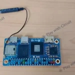
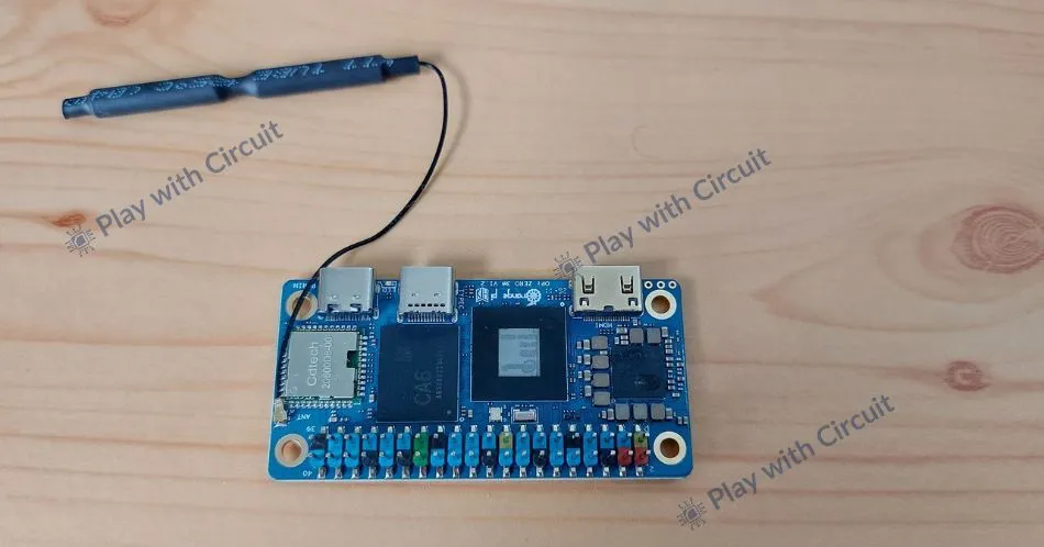
The Orange Pi Zero 3W is a compact Linux-based single-board computer. Despite its compact size, it includes a multi-core processor, memory, wireless connectivity, storage interfaces, display support, camera interfaces, and GPIO expansion— all onto a single board.
The board has Allwinner A733 processor, which combines high-performance and power-efficient CPU cores. This architecture allows the board to handle demanding workloads such as multitasking, running Linux applications, and image processing with reasonable power consumption. Whether you’re hosting a lightweight server, processing sensor data, or running multiple applications simultaneously, the processor provides enough performance for a wide range of development tasks.
For applications involving machine learning and computer vision, the board also includes a dedicated Neural Processing Unit (NPU) capable of accelerating AI workloads. It makes AI tasks such as object detection, image classification, and facial recognition more efficient.
The board supports high-speed LPDDR5 memory up to 16 GB. This is particularly beneficial when running graphical desktop environments, Docker containers, web dashboards, or multiple background services. Storage flexibility is another advantage of the Orange Pi Zero 3W. Users can boot the system from a microSD card, onboard eMMC storage, or high-speed UFS storage.
For multimedia and display-based projects, the Orange Pi Zero 3W provides multiple display interfaces including Mini HDMI, MIPI DSI, and DisplayPort over USB Type-C. Whether you’re building a smart dashboard, industrial HMI, or portable display device, the board offers the flexibility needed to connect various types of displays. The board also includes dual MIPI CSI camera interfaces, making it suitable for camera-based applications. Combined with the onboard AI acceleration capabilities, these camera interfaces allow developers to experiment with computer vision and edge AI applications directly on the board.
For hardware interfacing and electronics projects, the Orange Pi Zero 3W features a 40-pin GPIO header. Through this header, you can connect sensors, displays, motors, relays, communication modules, and various peripheral devices. This makes the board an excellent platform for building custom hardware projects. Another notable feature is the inclusion of PCIe expansion support. This interface can be used to connect high-speed peripherals such as NVMe storage devices, network adapters, or specialized accelerator hardware.
Technical Specifications
| Feature | Specification |
|---|---|
| Processor | Allwinner A733 |
| CPU | 2× Cortex-A76, 6× Cortex-A55 |
| Clock Speed | Up to 2 GHz |
| GPU | Imagination PowerVR BXM-4-64 MC1 |
| NPU | Up to 3 TOPS @INT8 |
| RAM | LPDDR5 up to 16GB |
| Wireless | Wi-Fi 6 + Bluetooth 5.4 |
| Storage | microSD, eMMC, UFS |
| Video Output | Mini HDMI 2.0, Type-C DP, MIPI DSI |
| Camera | Dual MIPI CSI |
| Expansion | PCIe 3.0 x1 |
| GPIO Header | 40 Pins |
| Power Supply | 5V/3A USB Type-C |
Key Features of Orange Pi Zero 3W
Octa-core Processor
The board is powered by Allwinner A733 processor which combines high-performance 2xA76 cores and 6xA55 efficiency cores (up to 2.0 GHz) in an eight-core heterogeneous design. This design allows demanding tasks to run on powerful cores while background processes execute on low-power cores.

Dedicated AI Accelerator
One of the most interesting additions is the built-in NPU capable of delivering up to 3 TOPS (Trillion Operations Per Second) of computing power. The accelerator supports multiple data formats including INT8, INT16, FP16, and BF16, making it suitable for machine-learning inference applications.

LPDDR5 Memory
The Zero 3W supports Low Power Double Data Rate Version 5 (LPDDR5) RAM up to 16 GB. Higher bandwidth memory improves multitasking and responsiveness, especially when running Ubuntu Desktop or AI applications.

Wi-Fi 6 and Bluetooth 5.4
Wireless connectivity is handled by an integrated module supporting Wi-Fi 6 and Bluetooth 5.4 Bluetooth Low Energy (BLE). This makes the board ideal for IoT devices and wireless communication.
 Rich Multimedia and Expansion Options
The board provides a range of interfaces for connecting displays, cameras, storage devices, and external hardware. It supports 4-lane Mini HDMI 2.0 output, USB Type-C DP Alt Mode, and MIPI-DSI, with support for dual independent displays. For camera applications, it includes two 4-lane MIPI CSI interfaces.
Flexible Storage Options
The Orange Pi Zero 3W supports multiple storage options, including a TF card slot along with optional onboard eMMC and UFS storage. This gives you flexibility to choose removable storage for development and testing or faster onboard storage for applications that require more reliable and dedicated storage.
Ready to try the Orange Pi Zero 3W?
Get the Orange Pi Zero 3W and follow this guide from the initial hardware setup and operating system installation to GPIO control.
Hardware Overview of Orange Pi Zero 3W
Top Side
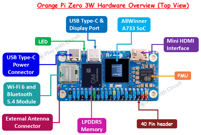
AllWinner A733 SoC This is the main processor of the board. The A733 integrates an octa-core CPU, GPU, NPU, and memory controller into a single chip.
LPDDR5 Memory The onboard LPDDR5 RAM stores the data and programs currently being used by the operating system.
USB Type-C Power Connector This connector supplies power to the board using a 5V/3A USB Type-C adapter.
USB Type-C & Display Port The second USB Type-C connector supports DisplayPort Alternate Mode, allowing compatible monitors to be connected directly through a USB Type-C to DisplayPort cable.
Mini HDMI Interface The Mini HDMI connector provides video output to an external monitor or television, supporting resolutions up to 4K at 60 Hz.
Wi-Fi 6 and Bluetooth 5.4 Module The onboard wireless module provides high-speed Wi-Fi and Bluetooth connectivity.
External Antenna Connector The board includes an external antenna connector to enhance Wi-Fi and Bluetooth signal quality.
Power Management Unit (PMU) The PMU regulates and distributes power to different components on the board to ensure stable operation.
Status LED The onboard LED provides visual feedback during power-up and system operation.
40-Pin Header The GPIO header allows external hardware such as sensors, displays, motors, relays, and communication modules to be connected. It supports interfaces including GPIO, UART, I²C, SPI, and PWM, making it the primary expansion interface for electronics projects.
Bottom Side
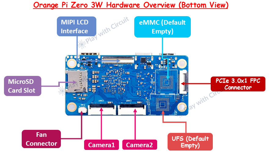
microSD Card Slot The microSD card slot also known as TF(TransFlash) card slot is the most common storage option for beginners. It is used to install and boot operating system.
MIPI DSI LCD Connector This board supports Mobile Industry Processor Interface (MIPI) Display Serial Interface (DSI). This interface allows compatible LCD displays and touchscreens to be connected directly to the board.
Camera Connectors (Camera 1 & Camera 2) The board includes two MIPI Camera Serial Interface (CSI) camera connectors for attaching supported camera modules.
Fan Connector The dedicated fan connector allows an external cooling fan to be attached.
eMMC Storage This board supports onboard Embedded Multimedia Card (eMMC) storage which is more reliable and faster than SD card to run Linux.
UFS Storage For applications requiring even higher storage performance, the board also supports Universal Flash Storage (UFS).
PCIe 3.0 x1 FPC Connector Peripheral Component Interconnect Express(PCIe) is an High-speed expansion interface, it allows developers to connect devices that need much higher bandwidth than USB can typically provide, such as NVMe SSDs, high-speed networking hardware, or other PCIe peripherals.
Orange Pi Zero 3W Pinout
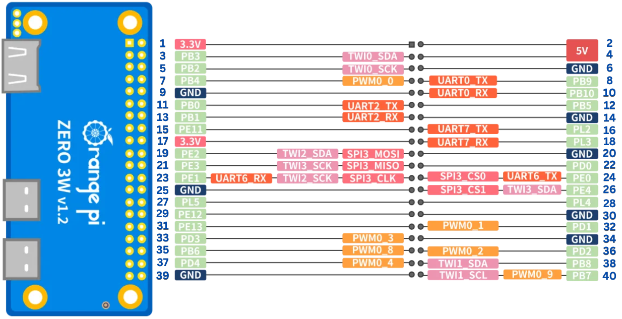
Power Pins (3.3V & 5V)
The GPIO header provides both 3.3V and 5V power pins to supply external circuits.
- 3.3V pins are commonly used to power low-voltage sensors, modules, and integrated circuits.
- 5V pins can power devices that require a higher operating voltage.
| Pin | Function |
|---|---|
| Pin 1 | 3.3V Power |
| Pin 2 | 5V Power |
| Pin 4 | 5V Power |
| Pin 17 | 3.3V Power |
Ground (GND) Pins
The board includes multiple ground pins for connecting external devices. Pins 6, 9, 14, 20, 25, 30, 34 and 39 are Ground Pins.
UART Pins
The Orange Pi Zero 3W provides multiple UART interfaces for serial communication. These interfaces are commonly used for serial debugging, communicating with microcontrollers, GPS modules, and other UART-enabled devices.
| Physical Pin | GPIO Identifier | UART Function |
|---|---|---|
| Pin 8 | PB9 | UART0_TX |
| Pin 10 | PB10 | UART0_RX |
| Pin 11 | PB0 | UART2_TX |
| Pin 13 | PB1 | UART2_RX |
| Pin 16 | PL2 | UART7_TX |
| Pin 18 | PL3 | UART7_RX |
| Pin 23 | PE1 | UART6_RX |
| Pin 24 | PE0 | UART6_TX |
I²C (TWI) Pins
Orange Pi refers to I²C as TWI (Two-Wire Interface).
| Physical Pin | GPIO Identifier | I²C Bus |
|---|---|---|
| Pin 3 | PB3 | TWI0_SDA |
| Pin 5 | PB2 | TWI0_SCK |
| Pin 19 | PE2 | TWI2_SDA |
| Pin 23 | PE1 | TWI2_SCK |
| Pin 21 | PE3 | TWI3_SCK |
| Pin 26 | PE4 | TWI3_SDA |
| Pin 38 | PB8 | TWI1_SDA |
| Pin 40 | PB7 | TWI1_SCK |
SPI Pins
The board provides an SPI interface for high-speed communication. with external peripherals. SPI uses separate lines for transmitting data, receiving data, synchronization, and device selection, making it faster than I²C for many applications.
| Physical Pin | SPI Signal | GPIO Identifier | Function |
|---|---|---|---|
| Pin 19 | SPI3_MOSI | PE2 | Transfers data from the Orange Pi (master) to the connected SPI device (slave). |
| Pin 21 | SPI3_MISO | PE3 | Receives data from the connected SPI device back to the Orange Pi. |
| Pin 23 | SPI3_CLK | PE1 | Provides the clock signal that synchronizes data transfer between the master and the slave. |
| Pin 24 | SPI3_CS0 | PE0 | Selects the first SPI device for communication. |
| Pin 26 | SPI3_CS1 | PE4 | Selects the second SPI device, allowing multiple SPI peripherals to share the same bus. |
PWM Pins
The Orange Pi Zero 3W provides several PWM (Pulse Width Modulation) channels. PWM generates digital pulses with a variable duty cycle, allowing software to control the average output voltage.
| Physical Pin | GPIO Identifier | PWM Channel |
|---|---|---|
| Pin 7 | PB4 | PWM0_0 |
| Pin 32 | PD1 | PWM0_1 |
| Pin 33 | PD3 | PWM0_3 |
| Pin 35 | PB6 | PWM0_8 |
| Pin 36 | PD2 | PWM0_2 |
| Pin 37 | PD4 | PWM0_4 |
| Pin 40 | PB7 | PWM0_9 |
Supported Operating Systems
The Orange Pi Zero 3W officially supports the following operating systems.
Ubuntu
Ubuntu is one of the most popular operating systems on Linux and is highly recommended for beginners due to its large community support, extensive documentation, and easy-to-use package management system. It is suitable for:
- Learning Linux
- Python programming
- Embedded software development
- Web servers
- Docker applications
- AI and computer vision projects
Debian
Debian is a lightweight and highly stable Linux distribution known for its reliability and long-term support. It consumes fewer system resources than many desktop-focused Linux distributions. Its stability and efficient resource usage make it well suited for applications that are expected to run continuously for long periods with minimal maintenance. It is suitable for:
- Embedded systems
- Industrial applications
- IoT gateways
- Network servers
Android
Android transforms the Orange Pi Zero 3W into a multimedia and smart display platform. It provides a familiar graphical interface and supports Android applications, making it suitable for touchscreen devices and interactive displays. It is suitable for:
- Digital signage
- Smart kiosks
- Multimedia players
- Touchscreen interfaces
- Android-based embedded devices
Downloading the Operating System
Before powering up your Orange Pi Zero 3W, you’ll need to install an operating system on a microSD card or compatible onboard storage. Orange Pi provides official operating system images that can be downloaded from its website.
Step 1: Visit the Official Orange Pi Website
Open your web browser and visit the official Orange Pi website. Navigate to the Downloads section and locate the Orange Pi Zero 3W product page: http://www.orangepi.org/html/hardWare/computerAndMicrocontrollers/service-and-support/Orange-Pi-Zero-3W.html
You’ll find official operating system images, user manuals, source code, and other resources available for download.
Step 2: Choose the Operating System
Select the operating system based on your application.
- Choose Ubuntu if you’re learning Linux or developing general-purpose applications.
- Choose Debian for lightweight embedded or server projects.
- Choose Android for multimedia and touchscreen applications.
Step 3: Download the Image File
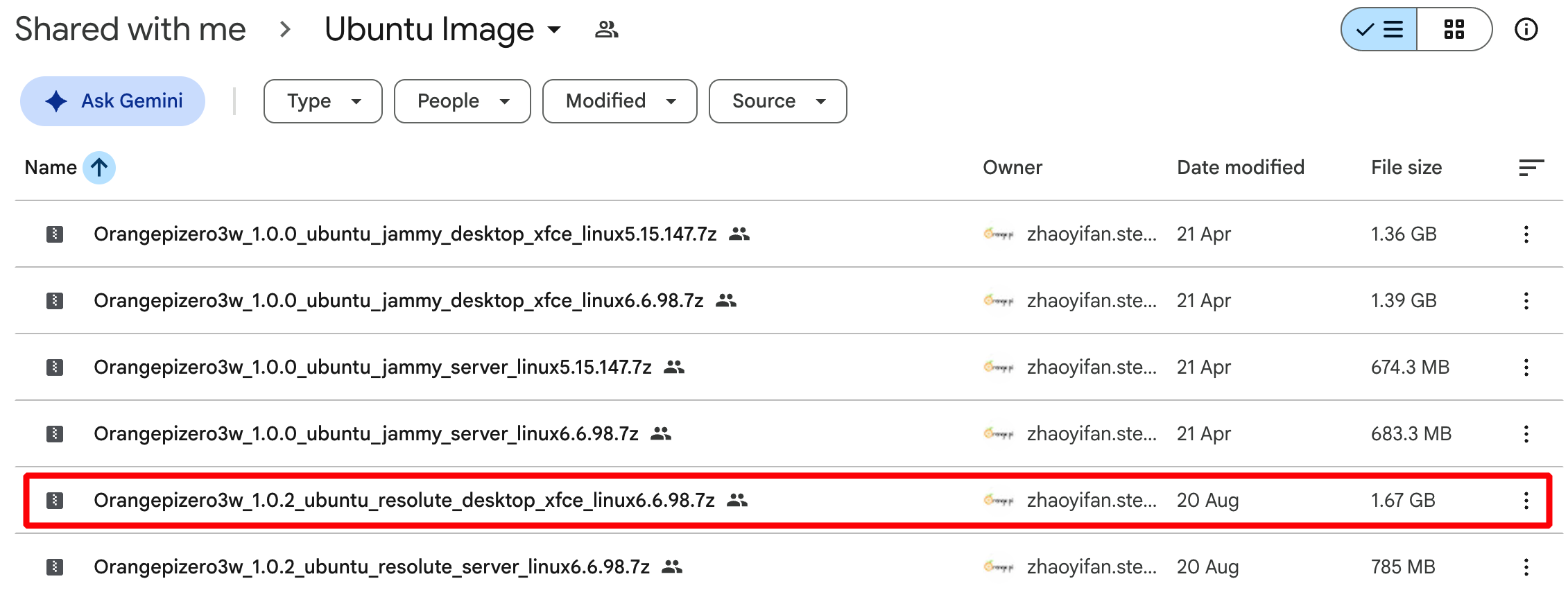
Click the download link for your preferred operating system. The images for ubuntu OS is provided at this link: https://drive.google.com/drive/folders/1sIFvfLJKRBOK06qqZ2_P0nx33mui3frB
The operating system image is usually provided as a compressed archive (such as .img.xz or .7z) to reduce download size. Depending on your internet connection, the download may take several minutes.
Step 4: Extract the Downloaded File
After the download completes, extract the compressed archive using software such as:
- 7-Zip (Windows)
- WinRAR
- The built-in Archive Manager (Linux)
- The Archive Utility (macOS)
After extraction, you’ll obtain an .img file, which is the operating system image that will be written to the storage device.
Installing the Operating System on a microSD Card
The easiest way to install the operating system is by using Rufus Software, a free utility available for Windows, macOS, and Linux.
Step 1: Install Rufus
Download Rufus from its official website and install it on your computer. Once installed, launch Rufus.
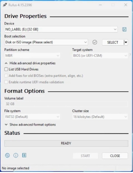
Step 2: Insert the microSD Card
Insert a Class 10 or higher microSD card into your computer using a compatible card reader.
For the best experience, use a 16 GB or 32 GB card with an A1 or A2 performance rating, as these offer better read/write speeds and improved reliability.
Step 3: Select the Target Device
In Rufus, select the microSD card under Device. Double-check the selected device before continuing. Choosing the wrong storage device could result in the loss of its existing data.
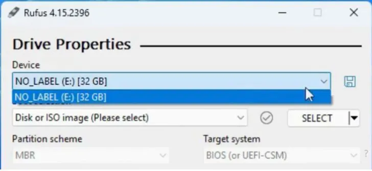
Step 4: Select the Disk or ISO image
Select the ISO image option.
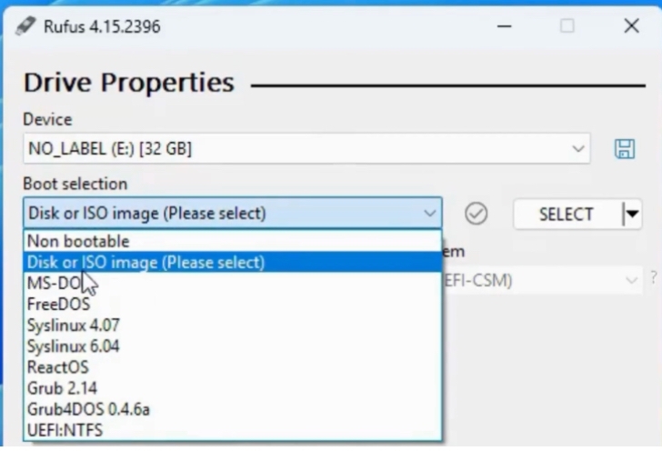
Step 5: Select the Operating System Image
Browse to the Ubuntu image that you downloaded for the Orange Pi Zero 3W.

Step 6: Start the Flashing Process
Click Start to begin writing the operating system image to the microSD card. The flashing process may take several minutes depending on the image size and the speed of your storage device.
Step 7: Wait for Verification
After writing the image, Rufus automatically verifies the data to ensure the operating system has been copied correctly. Once verification is complete, safely eject the microSD card from your computer.
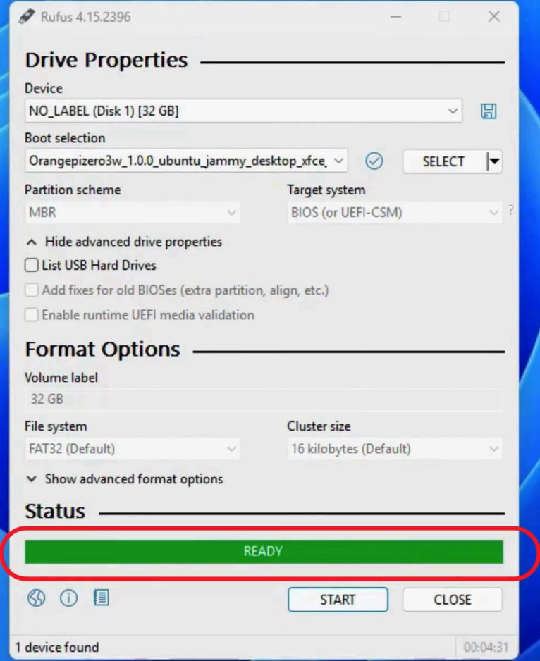
Step 8: Insert the Card into the Orange Pi Zero 3W
Insert the prepared microSD card into the board’s microSD card slot. Your Orange Pi Zero 3W is now ready for its first boot. Once your Ubuntu booted successfully then connect with the wifi, update ubuntu and browse internet.
Using WiringOP Library on Orange Pi
WiringOP is a C library for Orange Pi boards that allows you to easily control the board’s hardware peripherals such as GPIO pins, I²C, SPI, UART, and PWM from user-space applications. One of the advantages of wiringOP is that it can be used in two different ways:
- From the Linux terminal (Command Line Utility)
- From C/C++ programs
Controlling GPIO using Command line utility from Linux Terminal
In this method, GPIO pins are controlled directly from the Linux terminal using the WiringOP command-line utility. This provides a simple way to configure a GPIO pin, change its logic state, and verify the result without writing a separate program in C.
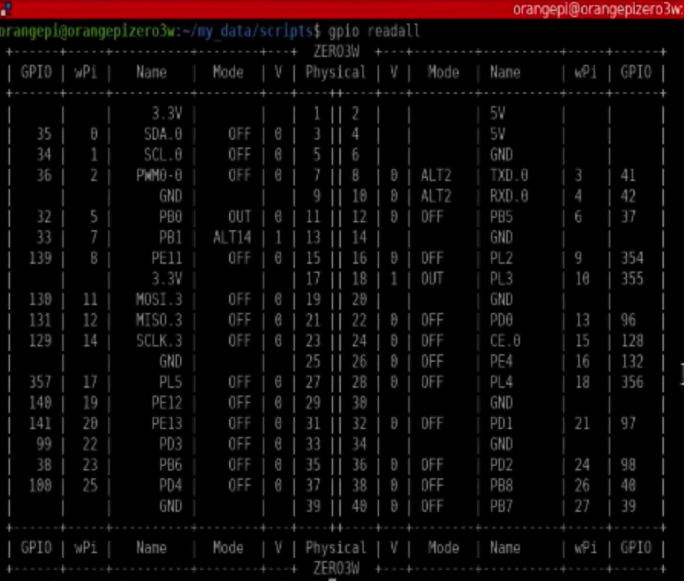
CMD: gpio_readall
Before performing any GPIO operation, it is useful to check the current pin configuration and understand how the physical pins are mapped to WiringOP numbers. gpio_readall command displays a complete overview of the Orange Pi Zero 3W’s 40-pin header, including the physical pin number, WiringOP (wPi) number, GPIO identifier, pin mode, and current logic level as shown below. The output helps you determine which WiringOP number should be used when sending GPIO commands.
An important point to understand is that the number used in a WiringOP command is not the physical pin number. For example, in the output, wPi 5 corresponds to physical Pin 11, and this pin is identified as PB0.
CMD: gpio mode 5 OUT
This command configures WiringOP pin 5 as an output.
Here, 5 refers to WiringOP pin 5, which maps to physical Pin 11 (PB0) on the Orange Pi Zero 3W.
CMD: gpio write 5 1
This command sets the pin PB0 to HIGH.
CMD: gpio write 5 0
This command sets the pin PB0 to LOW.
Controlling GPIO using C/C++ programs
Here is the code to toggle the pin PB0, which is physical pin 11 on the Orange Pi board.
#include <wiringPi.h>
#include <stdio.h>

#define LED_PIN 5      // wiringOP pin number (Physical Pin 11)

int main(void)
{
    if (wiringPiSetup() == -1)
    {
        printf("Failed to initialize wiringOP!\n");
        return 1;
    }

    pinMode(LED_PIN, OUTPUT);

    while (1)
    {
        digitalWrite(LED_PIN, HIGH);
        delay(500);

        digitalWrite(LED_PIN, LOW);
        delay(500);
    }

    return 0;
}
Code Explanation
The program begins by including two header files.
wiringPi.hprovides the functions required to configure and control the GPIO pins using the WiringOP library.stdio.his the standard C library used for input and output operations, such as printing messages to the terminal.
Next, we create a constant named LED_PIN with a value of 5.
#include <wiringPi.h>
#include <stdio.h>

#define LED_PIN 5
// wiringOP pin number (Physical Pin 11)
In the main function, before accessing any GPIO pin, we initialize WiringOP library.
The wiringPiSetup() function prepares the GPIO subsystem for use. If initialization fails, the function returns -1.
The program then displays an error message and terminates with return 1. This prevents the application from attempting to control GPIO pins before the library has been initialized successfully.
int main(void)
{
    if (wiringPiSetup() == -1)
    {
        printf("Failed to initialize wiringOP!\n");
        return 1;
    }
pinMode function configures LED_PIN as a digital output. Since an LED needs to receive output signals from the Orange Pi, the pin must be configured as an OUTPUT.
The digitalWrite() function changes the logic level of the GPIO pin. It sets the pin to HIGH, outputs a high logic level, turning the connected LED ON. The program waits for 500 milliseconds (0.5 seconds) before executing the next instruction.
Then, we change the GPIO pin to a LOW logic level, turning the LED OFF. The program waits another 500 milliseconds before repeating the loop. As a result, the LED blinks continuously with a one-second cycle: 0.5 seconds ON and 0.5 seconds OFF.
    pinMode(LED_PIN, OUTPUT);

    while (1)
    {
        digitalWrite(LED_PIN, HIGH);
        delay(500);

        digitalWrite(LED_PIN, LOW);
        delay(500);
    }

    return 0;
}
Important Scripts
These scripts provide a practical way to understand how the Orange Pi Zero 3W behaves while running.
Temperature monitoring script helps you observe the board’s thermal behavior and GPIO monitoring script helps users understand and test the state of the board’s GPIO pins in real time.
Continuous Temperature Monitoring
This script continuously reads the temperature values reported by the Orange Pi Zero 3W and displays them in the terminal. It automatically checks all available thermal zones and refreshes the readings every second, making it useful for observing temperature changes while the board is running different workloads.
#!/bin/bash
while true
do
    clear
    echo "Orange Pi Temperature Monitor"
    echo "============================="

    for zone in /sys/class/thermal/thermal_zone*
    do
        TYPE=$(cat "$zone/type")
        TEMP=$(cat "$zone/temp")
        printf "%-20s %.1f°C\n" "$TYPE" "$(echo "$TEMP/1000" | bc -l)"
    done

    sleep 1
done
Code Explanation
The script starts a continuous loop with while true. At the beginning of each cycle, clear removes the previous output and the echo commands print the monitor heading.
The for loop then searches through the thermal zones available under /sys/class/thermal/. For each zone, the script reads its sensor name using "$zone/type" and its current temperature using "$zone/temp".
The temperature reported by Linux is typically expressed in millidegrees Celsius. Therefore, the script divides the value by 1000 and uses bc -l to calculate the temperature with decimal precision. The printf command then formats the sensor name and temperature into a clean, readable output.
Finally, sleep 1 pauses the script for one second before the process starts again.
Continuous GPIO monitoring
This Bash script provides a simple way to monitor the GPIO pins of the Orange Pi Zero 3W directly from the Linux terminal. Instead of checking the GPIO status manually each time, the script repeatedly runs the gpio readall command and refreshes the output automatically.
#!/bin/bash

while true
do
    clear
    echo "Orange Pi GPIO Monitor"
    echo "============================="
    gpio readall
    sleep 0.1
done
Code Explanation
The #!/bin/bash line tells Linux to execute the script using the Bash shell. The while true loop then keeps the monitoring process running continuously. Inside the loop, clear removes the previous output from the terminal, while the echo commands display a heading for the GPIO monitor.
The gpio readall command is responsible for reading and displaying the GPIO information, including the pin numbers, GPIO identifiers, modes, and current logic states. This allows you to see changes in the GPIO pins without repeatedly entering the command manually.
Finally, sleep 0.1 introduces a 0.1-second delay before the loop runs again. This means the terminal is refreshed approximately 10 times per second, providing near real-time monitoring while avoiding an unnecessarily tight loop.