

Making two or more Arduinos communicate wirelessly can unlock endless possibilities for your projects— from remote sensing and wireless data communication systems to smart home automation systems.
For adding wireless capabilities to your Arduino projects nRF24L01+ transceiver module is a great choice. With its ability to communicate over long distances, the nRF24L01+ is widely used by makers and developers.
In this tutorial, we’ll show you exactly how to get started with the nRF24L01+ module and Arduino. You’ll learn how to set up two-way communication. First, we’ll send a basic message from one Arduino to another. Next, we’ll learn how to use multiple nRF24L01+ transmitters to send commands to a single receiver. Let’s dive in!
What is NRF24L01+?
NRF24L01+ is a low-cost single-chip wireless transceiver RF module that sends and receives data. The nRF24L01+ operates at a voltage between 1.9V to 3.6V and its logic pins are not 5V tolerant. So, when using it with 5V microcontrollers such as Arduino, a 3.3V regulator and level shifting are required for safe operation. It is a power-efficient device as it consumes around 11.3 mA while transmitting and 13.5 mA in receive mode. In low-power applications, it can switch to standby mode, consuming only 22 µA, or even enter power-down mode, using just 900 nA—which is ideal for battery-powered wireless projects.
The standard version of the module includes a small PCB trace antenna, which works well for ranges up to 50–100 meters in open space. For applications needing longer range, an enhanced version with a power amplifier (PA) and low-noise amplifier (LNA), along with an external antenna, can be used. It can communicate over distances up to 1000 meters (1 kilometer). Lower data rates like 250 kbps can further increase the effective range by reducing noise sensitivity.

Technical Specifications of nRF24L01+ Module
| Frequency range | 2.4 – 2.5GHz ISM band |
| Data rates | 250Kbps / 1Mbps / 2Mbps |
| Max. output power | 0dBm |
| Operating voltage | 1.9 – 3.6V |
| Max. operating current | 13.5mA |
| Standby current | 26µA |
| Logic inputs | 5V tolerant |
| Communication range | 100m (open space) |
| The speed of the digital interface (SPI) | 0-8Mbps |
For more details, please refer to the datasheet provided below.
How does the nRF24L01+ module work?
The nRF24L01+ module operates at 2.4 GHz ISM band and sends and receives data within the frequency range of 2.400 GHz to 2.525 GHz. This entire range is divided into segments called channels, each having bandwidth of 1 MHz when the data rate is set to 1Mbps. This gives a total of 126 channels (from channel 0 to 125) that can be used to communicate.
For two or more nRF24L01+ modules to communicate, they must be tuned to the same channel or the same RF frequency. For example if the transmitter is operating on 2500 MHz (channel 100), the receiver must also be tuned to the same frequency—2500 MHz. Only then it can successfully receive the data. If the receiver is tuned to a different frequency, it won’t be able to pick up the signal, and the data will be lost.
This configuration enables you to operate multiple devices in the same area without any interference as each group of devices operates on a different channel. The following image will help you to understand more.
![]()
Multiceiver
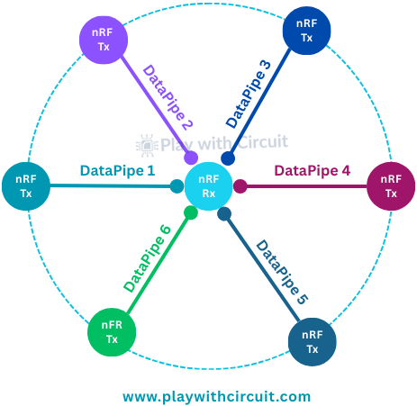
nRF24L01+ module has a feature called Multiceiver. It allows a single receiver to communicate with six different transmitters at the same time on the same RF channel.
In this configuration one channel is divided into six data pipes each with its unique address. However, it’s important to note that only one data pipe can actually receive a packet at any given moment. The following diagram will help you to understand more.
Enhanced ShockBurst
The nRF24L01+ uses Enhanced ShockBurst™ communication protocol embedded in its hardware. Here is how it handles data transmission:
- Automatic Packet Handling: It assembles the packets with preamble, address, and CRC.
- Packet Validation: When a packet is received, the receiver automatically verifies whether it’s valid or not.
- Packet Disassembly: Valid packets are automatically disassembled and placed into the module’s Rx FIFO (First In First Out).
- Acknowledgment Mechanism: After receiving a valid packet, the receiver automatically sends an acknowledgment (ACK) to the transmitter.
- Automatic Retransmission of Packets: If the transmitter doesn’t receive an ACK, it resends the packet until a confirmation is received.
These features make the nRF24L01+ module more efficient and reliable, especially in setups with multiple devices. They also reduce the workload for microcontrollers like the Arduino, since the module handles the addressing, filtering, and reception logic internally.
nRF24L01+ Module Variants
The nRF24 modules are available in basically three variants. Each version has the same core chip — the nRF24L01+ but differs in physical design, antenna configuration, and transmission range.
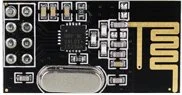
1. nRF24L01+ SOC with PCB Antenna
This is the most widely used version of the nRF24L01+ module which features an on-board PCB trace antenna. It is compact and lightweight but due to the smaller antenna its transmission range is lower— typically up to 100 meters in open space. In indoors, the range is reduced due to interference from walls, furniture, and other obstacles.
Despite its limited range, this version is very efficient in terms of power consumption and is suitable for short-range wireless communication between microcontrollers, such as Arduino boards in home automation or sensor-based projects.
2. nRF24L01+ with SMA Connector and External Antenna
The second variant has a SMA connector which allows you to attach an external duck antenna for improved transmission range. An external antenna improves signal strength, communication range and signal stability in environments with obstacles or interference.
3. nRF24L01+ with PA + LNA and External Antenna
The third variant includes the SMA connector along with an RFX2401C range extender chip. This chip has both a Power Amplifier (PA) and a Low-Noise Amplifier (LNA), along with transmit-receive switching logic. This configuration amplifies signals, resulting in a much greater communication range— up to 1000 meters in open space.
Even with the enhanced capabilities, this module is compatible with other nRF24 modules. You can easily swap it with the other variant in your project without altering anything.
What PA and LNA Do in nRF24L01+?
PA, or Power Amplifier strengthens the signal transmitted by the module. When the nRF24L01+ sends data wirelessly, the signal it generates is relatively weak. The PA boosts this signal, allowing it to travel much farther through the air.
LNA or Low-Noise Amplifier operates on the receiving end of the module. Incoming signals from far distances are often very weak. The LNA increases the strength of these weak signals without adding any electrical noise or interference.
When both the PA and LNA are integrated into the module, it can send data over longer distances and receive even the weakest signals with better clarity.
nRF24L01+ Module Pinout

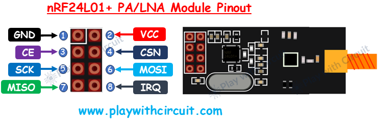
Let’s look at the pinouts of NRF24L01+ and the NRF24L01+ PA/LNA module.
GND This is the ground pin of the module. This pin is marked with a square pad which makes it easier to identify it.
VCC This pin provides power to the module. It works in a voltage range between 1.9V to 3.6V, but it works best at 3.3V. You can connect it directly to the Arduino 3.3V output.
CE (Chip Enable) This is an active-high control pin used to switch between active mode and standby mode. When CE is HIGH, the module is active and ready to transmit or receive data depending on its configuration. When it is LOW, the module goes into standby mode to conserve power.
CSN (Chip Select Not) This pin is active-low and it is normally kept HIGH. It is used in SPI communication between the nRF24L01+ module and the microcontroller. When it is set LOW, the module becomes active and is ready to receive data. This is especially important when multiple SPI devices share the same bus.
SCK (Serial Clock) This pin receives clock pulses from the microcontroller. These pulses synchronize the transfer of data between the microcontroller and the module.
MOSI (Master Out Slave In) This is the SPI data input line for the nRF24L01 module. Through this pin module receives the data from the microcontroller.
MISO (Master In Slave Out) This pin is the module’s SPI data output line. It sends data from the module back to the microcontroller.
IRQ (Interrupt Request) This is an active-low pin. This optional pin notifies the microcontroller when the data is available on the SPI bus.
Two Way Communication Between nRF24L01+ Modules
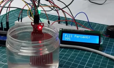
Now that we have a complete understanding of nRF modules, we will set up a handshake communication between two nRF modules. Here Initiator module sends a message and when it is received by another nRF module which is the designated responder, it replies to that message. The complete communication between Initiator and Responder is displayed on the LCD connected to the Arduino of Initiator module.
Hardware Requirement
| Component Name | Quantity | Remarks | Where to Buy |
|---|---|---|---|
| Arduino UNO R3 | 1 | Revision R3 | Amazon |
| LCD 16x2 | 1 | I2C support | Amazon |
| Jumper Wires | 1 | For Arduino and LCD connections | Amazon |
| USB Cable Type A to B | 1 | for programming Arduino UNO | Amazon |
| 12V Supply Adapter | 1 | For providing power to Arduino | Amazon |
| nRF24L01+ Modules | 1 | For interfacing with Arduino | Amazon |
Software Requirement
- Arduino IDE, Version 2.3.4 or above installed on your PC.
- LiquidCrystal_I2C Library by Frank de Brabander V 1.1.2
- RF24 Library by TMRh20 V 1.5.0
Steps to Install LCD library in Arduino IDE
- First open Arduino IDE .
- Then go to Library Manager and search “LiquidCrystal I2C Frank de Brabander”.
- Now Install “LiquidCrystal I2C” library.

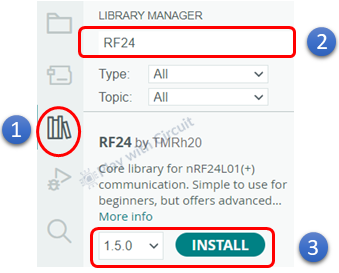
Steps to Install RF24 Library in Arduino IDE
- Open Arduino IDE
- Go to the Library Manager and search for “RF24 by TMRh20” library
- Click the Install button to download and install the library.
Commonly used Functions of RF24 Library
bool begin() It initializes the chip; verifies the radio responds, configures SPI. It is called once in setup() before any other RF24 calls.
Returns: true if the radio responds; false otherwise.
void setPALevel(rf24_pa_dbm_e level) This function is used to control the transmit power (PA level) of the nRF24L01+ module. PA stands for Power Amplifier, and adjusting its level allows you to balance range, power consumption, and noise/interference.
Parameter
level — choose one of the predefined constants:
-
RF24_PA_MIN → Lowest power (short range, least current)
-
RF24_PA_LOW → Moderate power
-
RF24_PA_HIGH → Long range
-
RF24_PA_MAX → Maximum range (highest current draw)
bool setDataRate(rf24_datarate_e speed) It is used to set the on-air data rate (bitrate) of the nRF24L01+ module. This determines how fast data is transmitted between the transmitter and receiver.
speed — choose one of the available data rate options:
-
RF24_250KBPS → Longest range, most stable (slowest)
-
RF24_1MBPS → Default speed, balanced performance
-
RF24_2MBPS → Fastest speed, short range
Returns: true when data rate was set successfully.
void setAutoAck(bool enable) This function enables or disables the Auto Acknowledgment (Auto-ACK) feature of the nRF24L01+ module — either globally or for a specific RX pipe.
Parameter
enable: true to enable Auto-ACK, false to disable it
void setRetries(uint8_t delay, uint8_t count) This function is used to configure the automatic retransmission behavior of the nRF24L01+ module. When Auto-ACK is enabled, this function controls how often and how quickly the transmitter retries sending a packet if it doesn’t receive an acknowledgment (ACK) from the receiver.
Parameters
delay(0–15): Sets the time between two retransmissions. Each step equals 250 µs, so the total delay = delay × 250 µs.
count(0–15): Sets how many times the radio will retry sending a packet before giving up.
Return: This function returns nothing (void).
void setChannel(uint8_t channel) This function is used to set the radio frequency channel on which the nRF24L01+ module communicates.
Each nRF24L01+ operates in the 2.4 GHz ISM band (2.400 GHz – 2.525 GHz), which is divided into 126 channels (0 – 125), each 1 MHz apart.
Parameter
channel (0 – 125): Selects the communication channel. Each step adds 1 MHz to the base frequency of 2400 MHz.
void setCRCLength(rf24_crclength_e length) This function is used to set the CRC (Cyclic Redundancy Check) length used for error detection in wireless communication between two nRF24L01+ modules. By adjusting the CRC length, you control how sensitive the module is to detecting transmission errors.
Parameters
RF24_CRC_8: Uses 1-byte CRC – faster, less reliable
RF24_CRC_16: Uses 2-byte CRC – slower, more robust
void setAddressWidth(uint8_t bytes) This function sets the address width (number of bytes) used by the nRF24L01+ module to identify transmitters and receivers.
Parameter
bytes: Number of address bytes to use. Acceptable values are 3, 4, or 5.
void openWritingPipe(const uint8_t* address) This function sets the transmit (TX) address of the nRF24L01+ module. It tells the module where to send data.
Parameters
address: A pointer to an array of bytes representing the destination address.
void openReadingPipe(uint8_t pipeNumber, const uint8_t* address) This function activates one of the receiver pipes (data channels) on the nRF24L01+ module and assigns it a unique address. Each nRF24L01+ receiver can listen on up to 6 different pipes (0–5) at the same time.
Parameters
-
pipeNumber: The pipe number to open (valid values: 0–5).
-
address: A pointer to a byte array containing the address of the transmitter.
void startListening() The function puts the nRF24L01+ module into receive (RX) mode. After this function is called, the radio begins listening for incoming data on all enabled reading pipes.
void stopListening() The function switches the nRF24L01+ module out of receive (RX) mode and prepares it for transmitting data (TX mode).
bool available(uint8_t* pipeNumber) This function checks whether the nRF24L01+ module has received new data, and also tells you which RX pipe that data came from.
Parameters
uint8_t* pipeNumber A pointer to a variable where the function will store the pipe number (0–5) that received the data.
Return: true when data is available in the RX buffer (and the pipe number is stored in your variable).
void read(void* buf, uint8_t len) This function is used on the receiver side to read incoming data from the nRF24L01+ module’s RX buffer (FIFO).
Parameters
-
buf: A pointer to the variable or array where you want to store the received data.
-
len: The number of bytes to read (must match the payload size sent by the transmitter).
bool write(const void* buf, uint8_t len) This function is used on the transmitter side to send data from one nRF24L01+ module to another. It transmits the given payload (message) to the address that was set using openWritingPipe().
Parameters
-
buf: Pointer to the data buffer (the message you want to send).
-
len: The number of bytes to send (maximum 32 bytes per packet).
Returns: true if an ACK was received; false on failure (no ACK).
void enableDynamicPayloads() This function allows the radio to send variable-length packets, so each message can be as short or as long as needed.
void disableDynamicPayloads() Function disables Dynamic Payload feature, goes back to a fixed-length payload.
void setPayloadSize(uint8_t size) This function defines the fixed size of data packets (payloads) that the nRF24L01+ will transmit or receive.
Parameters
size: The number of bytes in each payload. Acceptable range: 1 to 32 bytes.
void printDetails() It prints radio registers/settings to serial monitor. It is great for verifying channel, data rate, addresses, AA bits, etc.
All of the above functions belong to RF24 class—not standalone commands.
Wiring Connections
There will be two wiring connection diagrams one for the Initiator module and another for the responder module. The difference between both of them is that the initiator has an I2C LCD connected to it while the responder transmits its data over the serial port.
Here is the initiator wiring diagram:
 In the above wiring diagram, the NRF module is connected with the Arduino using SPI bus, through MISO, MOSI, CLK and CSN pins. Apart from these pins there are 3 pins one is Chip Enable, VCC (3.3V) and GND.
❕Note
If we are using base for the nRF module which internally converts 5V to 3.3V then we connect the power pin of base to the 5V pin of Arduino.

But if we use the module as it is then the power pin of the nRF module is directly connected to the 3.3v pin of Arduino like we are doing in the above diagram.
Also, the voltage level of Arduino(5V) for communication(SPI) with NRF module(3.3V) doesn’t instantaneously burn the module but it affects the module in long term. For the sake of simplicity we haven’t used the voltage shifter. But it is recommended to do so for industrial applications.
The connections between Arduino Uno and nRF Module are as follows:
| nRF Module | Arduino Side Pin |
|---|---|
| GND (Pin 1) | GND pin of Arduino |
| VCC (pin 2) | 3.3V pin of Arduino |
| CE (Pin 3) | 9 |
| CSN (Pin 4) | 10 |
| SCK (Pin 5) | 13 |
| MOSI (Pin 6) | 11 |
| MISO (Pin 7) | 12 |
| IRQ (Pin 8) | Not connected |
The wiring of the I2C LCD with Arduino is simple. Connect the Vcc and GND pins of I2C LCD with the Vcc and GND pins of the Arduino. SCL(clock) and SDA(data) pins of I2C LCD are connected to SCL and SDA pins of Arduino.
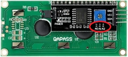
SCL and SDA pins are the same as pins A5 and A4 Analog input pins of Arduino where pink and blue wires are connected with LCD. These header pins are also connected to A5 and A4 pins of Arduino.
Make sure A0, A1, A2 address jumpers are not shorted when using I2C LCD. As in code we will be using Address 0x27 for the I2C LCD which will only be formed when these jumpers are not shorted in the I2C LCD.
Here is the wiring diagram for Responder:

The responder’s wiring diagram is the same as Initiator’s wiring diagram as far as RF module connections are involved. Also it doesn’t include any I2C LCD hence it has fewer connections.
Arduino Code for Initiator Module
In this sketch, one Arduino (the Initiator) sends the text “Are you there?” over a 2.4 GHz radio (nRF24L01+). After sending, it immediately switches to listening mode and waits up to 500 ms for a reply. If it receives “Yes”, it shows that on the I²C LCD and the Serial Monitor. If nothing comes back in time, it prints “No reply received.”
/*
Code to send “Are you there?” from one Arduino to another
and received reply and display complete communication on I2C LCD
by platwithcircuit.com
*/
#include <SPI.h>
#include <nRF24L01.h>
#include <RF24.h>
#include <LiquidCrystal_I2C.h>

// Init LCD at 0x27, 16x2
LiquidCrystal_I2C lcd(0x27, 16, 2);

// CE, CSN pins
RF24 radio(9, 10);
const byte communication_address[6] = "00001";  // should be same for both Arduinos

void setup() {
  boolean boRetval = false;
  // begin serial communication at baud 9600,n,8,1
  Serial.begin(9600);
  // initialize the LCD
  lcd.init();
  // Turn ON the Backlight
  lcd.backlight();
  // Clear the display buffer
  lcd.clear();
  // Initializes the RF24 object and the nRF24L01 IC along with SPI peripheral
  boRetval = radio.begin();
  if (boRetval == true) {
    // Sets the transmission address as communication_address
    radio.openWritingPipe(communication_address);
    // Enables Rx pipe 0 and bind it to communication_address
    radio.openReadingPipe(0, communication_address);
    // sets the RF power output to LOW
    radio.setPALevel(RF24_PA_LOW);
    // Choose on-air bitrate; lower rate = better range/robustness
    radio.setDataRate(RF24_250KBPS);
  }

  if (boRetval == true) {
    lcd.clear();
    lcd.setCursor(0, 0);
    lcd.print("RF Init");
    lcd.setCursor(0, 1);
    lcd.print("Successful");
    Serial.println("RF Init ");
    Serial.print("Successful");
    delay(1000);
  } else {
    lcd.clear();
    lcd.setCursor(0, 0);
    lcd.print("RF Init");
    lcd.setCursor(0, 1);
    lcd.print("Failed");
    Serial.println("RF Init ");
    Serial.print("Failed");
    while (1);
  }
}

void loop() {
  const char request[] = "Are you there?";
  const char expected_reply[] = "Yes";
  char reply[32] = "";
  bool timeout;
  unsigned long start_time;
  uint8_t len;

  timeout = true;
  // Takes the radio out of RX mode
  radio.stopListening();
  // transmits array named request
  bool boRetval = radio.write(request, sizeof(request));
  if (boRetval == true) {
    // Puts the radio into RX mode
    radio.startListening();
    // Displaying Sent Msg
    lcd.clear();
    lcd.setCursor(0, 0);
    lcd.print("Msg Sent:");
    lcd.setCursor(0, 1);
    lcd.print(request);
    Serial.print("\nSent:");
    Serial.print(request);

    start_time = millis();
    // Wait for reply for max 500ms
    while (millis() - start_time < 500) {
      // check if data is available in RX FIFO
      if (radio.available()) {
        memset(reply, 0x00, sizeof(reply));
        // read data available in Rx FIFO
        radio.read(reply, sizeof(reply));
        Serial.print("\nReceived: ");
        Serial.println(reply);
        if (strcmp(reply, expected_reply) == 0) {
          // Displaying received Msg
          lcd.clear();
          lcd.setCursor(0, 0);
          lcd.print("Msg Received:");
          lcd.setCursor(0, 1);
          lcd.print(reply);
          timeout = false;
          break;
        }
      }
    }

    // check if no data is received
    if (timeout) {
      lcd.clear();
      lcd.setCursor(0, 0);
      lcd.print("No reply received.");
      Serial.print("\nNo reply received.");
    }
  } else {
    // Displaying Sent Msg
    lcd.clear();
    lcd.setCursor(0, 0);
    lcd.print("Msg Sending");
    lcd.setCursor(0, 1);
    lcd.print("Failed");
    Serial.print("\nMsg Sending ");
    Serial.print("Failed");
  }

  delay(1000);  // wait before sending again
}
Code Explanation
The code starts by including three essential libraries:
First we include all the required libraries. SPI.h enables the SPI communication, nRF24L01.h handles the wireless radio module nRF24L01. LiquidCrystal_I2C.h lets Arduino control an LCD display through I2C pins (SDA & SCL).
#include <SPI.h>
#include <nRF24L01.h>
#include <RF24.h>
#include <LiquidCrystal_I2C.h>
Now, we create an lcd object at I2C address 0x27 with 16 columns and 2 rows.
Then, we create an RF24 radio object and connect it to CE (D9) and CSN (D10) on Arduino.
Next, we create an array to store the 5-byte pipe address. Both Initiator and Responder must use the same address bytes and the same address width to communicate.
// Init LCD at 0x27, 16x2
LiquidCrystal_I2C lcd(0x27, 16, 2);

// CE, CSN pins
RF24 radio(9, 10);
const byte communication_address[6] = "00001";  // should be same for both Arduinos
In the setup function, first we start the serial communication at 9600 baud. Then we initialize the LCD, turn on its backlight, and clear it.
void setup() {
  boolean boRetval = false;
  // begin serial communication at baud 9600,n,8,1
  Serial.begin(9600);
  // initialize the LCD
  lcd.init();
  // Turn ON the Backlight
  lcd.backlight();
  // Clear the display buffer
  lcd.clear();
Next we use radio.begin() to initialize the radio module. It returns true if it is working. If it returns false, that means the radio isn’t connected properly or isn’t responding.
If the radio starts correctly, we set one write pipe and enable read pipe 0 at the same address. This lets the Initiator transmit its request and then listen on pipe 0 for the reply. We pick RF24_PA_LOW (lower output power) to reduce noise/current draw during indoor testing, and RF24_250KBPS (slower air rate) to gain better sensitivity and range.
 // Initializes the RF24 object and the nRF24L01 IC along with SPI peripheral
  boRetval = radio.begin();
  if (boRetval == true) {
    // Sets the transmission address as communication_address
    radio.openWritingPipe(communication_address);
    // Enables Rx pipe 0 and bind it to communication_address
    radio.openReadingPipe(0, communication_address);
    // sets the RF power output to LOW
    radio.setPALevel(RF24_PA_LOW);
    // Choose on-air bitrate; lower rate = better range/robustness
    radio.setDataRate(RF24_250KBPS);
  }
We then show a clear “Successful” or “Failed” message on both LCD and Serial. If init fails, while(1); halts the sketch on purpose.
if (boRetval == true) {
    lcd.clear();
    lcd.setCursor(0, 0);
    lcd.print("RF Init");
    lcd.setCursor(0, 1);
    lcd.print("Successful");
    Serial.println("RF Init ");
    Serial.print("Successful");
    delay(1000);
  } else {
    lcd.clear();
    lcd.setCursor(0, 0);
    lcd.print("RF Init");
    lcd.setCursor(0, 1);
    lcd.print("Failed");
    Serial.println("RF Init ");
    Serial.print("Failed");
    while (1);
  }
}
In the loop function first we create an array named request and store the message “Are you there?” Then we define a constant string expected_reply holding the expected acknowledgment payload. This helps us check whether communication between the two Arduinos is working properly.
Then we create an array named reply that can hold up to 32 characters. This is where the received message from the other Arduino will be saved.
Next we define a variable that will later be used to check whether we waited too long for a reply. start_time variable will store the starting time when we begin waiting for a reply.
void loop() {
  const char request[] = "Are you there?";
  const char expected_reply[] = "Yes";
  char reply[32] = "";
  bool timeout;
  unsigned long start_time;
Next we declare an 8-bit unsigned integer (0–255) used to record the payload length actually read from the RX FIFO.
The radio can’t listen and transmit at the same time, so we call stopListening() first. radio.write() pushes the payload into the air; we pass sizeof(request) which includes the string’s null terminator (‘\0’), and that’s fine because the receiver reads into a 32-byte buffer and treats it as a string. When write() returns true, the packet was successfully sent. We immediately call startListening() to jump back to RX mode, ready to hear the reply. For visibility, we print the sent text on both the LCD and Serial Monitor.
uint8_t len;
timeout = true;
  // Takes the radio out of RX mode
  radio.stopListening();
  // transmits array named request
  bool boRetval = radio.write(request, sizeof(request));
  if (boRetval == true) {
    // Puts the radio into RX mode
    radio.startListening();
    // Displaying Sent Msg
    lcd.clear();
    lcd.setCursor(0, 0);
    lcd.print("Msg Sent:");
    lcd.setCursor(0, 1);
    lcd.print(request);
    Serial.print("\nSent:");
    Serial.print(request);
We store start_time = millis() and then loop while less than 500 ms have elapsed. Inside, radio.available() tells us a packet landed. We zero the reply buffer to ensure a clean C-string, then radio.read() copies the incoming bytes.
We log the text to Serial and check strcmp(reply, expected_reply). Here, we only declare success if the reply is exactly “Yes”. If that’s true, we show “Msg Received: Yes” on the LCD and clear the timeout flag.
start_time = millis();
    // Wait for reply for max 500ms
    while (millis() - start_time < 500) {
      // check if data is available in RX FIFO
      if (radio.available()) {
        memset(reply, 0x00, sizeof(reply));
        // read data available in Rx FIFO
        radio.read(reply, sizeof(reply));
        Serial.print("\nReceived: ");
        Serial.println(reply);
        if (strcmp(reply, expected_reply) == 0) {
          // Displaying received Msg
          lcd.clear();
          lcd.setCursor(0, 0);
          lcd.print("Msg Received:");
          lcd.setCursor(0, 1);
          lcd.print(reply);
          timeout = false;
          break;
        }
      }
    }
If the 500 ms window closes with no acceptable reply, we tell the user clearly on both LCD and Serial. If the send itself failed, we show “Msg Sending Failed”—this is distinct from “no reply” and very helpful in debugging. Finally, we pause for 1 second and repeat.
// check if no data is received
    if (timeout) {
      lcd.clear();
      lcd.setCursor(0, 0);
      lcd.print("No reply received.");
      Serial.print("\nNo reply received.");
    }
  } else {
    // Displaying Sent Msg
    lcd.clear();
    lcd.setCursor(0, 0);
    lcd.print("Msg Sending");
    lcd.setCursor(0, 1);
    lcd.print("Failed");
    Serial.print("\nMsg Sending ");
    Serial.print("Failed");
  }

  delay(1000);  // wait before sending again
}
Arduino Code for Responder Module
This Arduino sketch allows one nRF24L01+ module (the Responder) to receive the message “Are you there?” from another Arduino (the Initiator) and immediately send back a “Yes” reply.
/*
Code to send “Yes” message to another Arduino when this Arduino receives msg "Are you there?"
by platwithcircuit.com
*/
#include <SPI.h>
#include <nRF24L01.h>
#include <RF24.h>

// CE, CSN pins
RF24 radio(9, 10);
const byte communication_address[6] = "00001";  // should be same for both Arduinos

void setup() {
  // begin serial communication at baud 9600,n,8,1
  Serial.begin(9600);
  // Initializes the RF24 object and the nRF24L01 IC along with SPI peripheral
  bool boRetval = radio.begin();
  if (boRetval == true) {
    // Sets the transmission address as communication_address
    radio.openWritingPipe(communication_address);
    // Enables Rx pipe 0 and bind it to communication_address
    radio.openReadingPipe(0, communication_address);
    // sets the RF power output to HIGH
    // sets the RF power output to LOW
    radio.setPALevel(RF24_PA_LOW);
    // Choose on-air bitrate; lower rate = better range/robustness
    radio.setDataRate(RF24_250KBPS);
    radio.startListening();
    // Send init msg
    Serial.println("RF Init ");
    Serial.print("Successful");
  } else {
    Serial.println("RF Init ");
    Serial.print("Failed");
  }
}

void loop() {
  char receivedMessage[32] = "";
  const char request[] = "Are you there?";
  const char reply[] = "Yes";

  // check if data is available in RX FIFO
  if (radio.available()) {
    memset(receivedMessage, 0x00, sizeof(receivedMessage));
    // read data available in Rx FIFO
    radio.read(receivedMessage, sizeof(receivedMessage));
    Serial.print("\nReceived: ");
    Serial.println(receivedMessage);
    // Check if expected msg is received
    if (strcmp(receivedMessage, request) == 0) {
      // Takes the radio out of RX mode
      radio.stopListening();
      delay(200);
      // transmits array named reply
      radio.write(reply, sizeof(reply));
      Serial.println("Sent reply: Yes");
      // Puts the radio into RX mode
      radio.startListening();
    }
  }
}
Code Explanation
In the setup() function, we initialize the Serial Monitor and the nRF24L01+ module. If initialization is successful, the Responder configures both writing and reading pipes using the same address. Here we are using pipe 0 for reading.
Next, we configure the radio’s power level and data rate for stable communication.
void setup() {
  // begin serial communication at baud 9600,n,8,1
  Serial.begin(9600);
  // Initializes the RF24 object and the nRF24L01 IC along with SPI peripheral
  bool boRetval = radio.begin();
  if (boRetval == true) {
    // Sets the transmission address as communication_address
    radio.openWritingPipe(communication_address);
    // Enables Rx pipe 0 and bind it to communication_address
    radio.openReadingPipe(0, communication_address);
    // sets the RF power output to HIGH
    // sets the RF power output to LOW
    radio.setPALevel(RF24_PA_LOW);
    // Choose on-air bitrate; lower rate = better range/robustness
    radio.setDataRate(RF24_250KBPS);
    radio.startListening();
    // Send init msg
    Serial.println("RF Init ");
    Serial.print("Successful");
  } else {
    Serial.println("RF Init ");
    Serial.print("Failed");
  }
}
In the loop, we declare three variables:
receivedMessage[32]is a buffer to hold the received message. The nRF24L01+ supports a maximum payload of 32 bytes, so this size ensures the full message fits safely.- request — the specific text message the Responder expects to receive.
- reply — the message that will be sent back when the correct request arrives.
void loop() {
  char receivedMessage[32] = "";
  const char request[] = "Are you there?";
  const char reply[] = "Yes";
The function radio.available() checks whether a new message has arrived.
If data is available, the code clears the receivedMessage buffer using memset() to avoid leftover characters from previous messages.
Then the line radio.read(receivedMessage, sizeof(receivedMessage)) copies the received bytes into the buffer.
The received message is printed to the Serial Monitor so you can verify what the module has received.
// check if data is available in RX FIFO
  if (radio.available()) {
    memset(receivedMessage, 0x00, sizeof(receivedMessage));
    // read data available in Rx FIFO
    radio.read(receivedMessage, sizeof(receivedMessage));
    Serial.print("\nReceived: ");
    Serial.println(receivedMessage);
Once the message is read, we need to verify if it’s the one we expect.
The function strcmp() compares two strings.
If both are exactly the same, it returns 0.
Here we compare the received message with our known request “Are you there?”.
- If they match → It means the Initiator is asking us if we’re there.
- If not → We ignore it, since it might be noise or data from another device.
If the expected message was received, the Responder prepares to send a reply:
radio.stopListening()switches the radio from RX (receive) mode to TX (transmit) mode.delay(200)→ Waits 200 milliseconds. It ensures the radio hardware is ready for transmission and avoids overlapping with any unfinished incoming signals.radio.writesends the reply message “Yes” back to the Initiator.
The Serial Monitor logs the confirmation. Once the message is sent, the Responder immediately returns to listening mode.
 // Check if expected msg is received
    if (strcmp(receivedMessage, request) == 0) {
      // Takes the radio out of RX mode
      radio.stopListening();
      delay(200);
      // transmits array named reply
      radio.write(reply, sizeof(reply));
      Serial.println("Sent reply: Yes");
      // Puts the radio into RX mode
      radio.startListening();
    }
  }
}
Output
Communication between Multiple nRF24L01+ Transmitters to a Single Receiver
Here we will send requests from two transmitter nRF24L01+ modules to single receiver nRF24L01+. Receiver will toggle an LED based on the requests received from transmitting modules. Whenever the LED is toggled, the receiver will also display information on the Serial Monitor showing which transmitter sent the request. This helps us clearly identify the source of each command. It is important to note that all the three nodes (the two transmitters and the receiver) must share the same address.
Each transmitter module has a pushbutton connected to its Arduino board. When you press the button, that transmitter sends a wireless request through the nRF24L01+. The receiver immediately acts on this request by toggling its LED and printing a message that confirms the action along with the identity of the transmitting node.
The toggling of LEDs is initiated by the buttons connected to the Arduino of each transmitter module. When you press the button, that transmitter sends a wireless request through the nRF24L01+. The receiver immediately acts on this request by toggling its LED.
In our setup, we are interfacing two Arduino Uno with transmitters and an Arduino Nano with receiver.
Hardware Requirement
| Component Name | Quantity | Remarks | Where to Buy |
|---|---|---|---|
| Arduino UNO R3 | 1 | Revision R3 | Amazon |
| Arduino Nano | 1 | - | Amazon |
| Push Button | 2 | - | Amazon |
| Jumper Wires | 1 | For connections of Arduino and nRF modules | Amazon |
| USB Cable Type A to B | 1 | for programming Arduino UNO | Amazon |
| 12V Supply Adapter | 1 | For providing power to Arduino | Amazon |
| nRF24L01+ Modules | 1 | For interfacing with Arduino | Amazon |
| 5mm LED | 1 | Connected to receiver | Amazon |
| 100 ohm resistor | 1 | To limit current via LED | Amazon |
Software Requirement
- Arduino IDE, Version 2.3.4 or above installed on your PC.
- LiquidCrystal_I2C Library by Frank de Brabander V 1.1.2
- RF24 Library by TMRh20 V 1.5.0
Wiring Connections
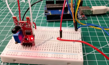
In this project two transmitters are connected with Arduino Uno and one receiver is connected with Arduino Nano. The wiring diagram of transmitter is given below:

The nRF module’s connection is the same as before, except for few changes. Here we have connected a button to pin 2 of Arduino. The button is pulled up using a 10K resistor. The debouncing is software controlled. Here we are not using LCD. The wiring diagram for both the transmitters is the same.
The wiring diagram for receivers is given below:

In this receiver module we are using Arduino Nano, as both Uno and Nano boards are pin compatible hence the connections with nRF module will remain same. Also here we are using an LED to indicate the button press event on transmitter side. The anode pin of LED is connected to pin 3 on the Nano board and the cathode is connected to ground via 100-ohm resistance to limit the current flowing through it.
Arduino Code for Transmitter Module
This Arduino sketch turns your Uno and nRF24L01+ into a simple wireless button transmitter. When you press the button connected to pin 2, the module sends a short text message to an Arduino receiver that controls an LED. Both transmitters use the same code — only the request string changes. The first transmitter sends “LED_TOGGLE1” and the second sends “LED_TOGGLE2.”
The code for both the transmitter Arduinos are the same except the request string in transmitter 1 is:
const char request[] = “LED_TOGGLE1”;
where as it is
const char request[] = “LED_TOGGLE2”;
in the code of transmitter 2
/*
Code to get the status of button connected to pin 2 to toggle LED connected to Receiver Arduino by platwithcircuit.com
*/
#include <SPI.h>
#include <nRF24L01.h>
#include <RF24.h>

#define BUTTON_PIN 2

// CE, CSN pins
RF24 radio(9, 10);
const byte communication_address[6] = "NET01";  // Address of first Transmitter
const char request[] = "LED_TOGGLE1";

void setup() {
  // Initialize button pin
  pinMode(BUTTON_PIN, INPUT);
  // begin serial communication at baud 9600,n,8,1
  Serial.begin(9600);
  // Initializes the RF24 object and the nRF24L01 IC along with SPI peripheral
  bool boRetVal = radio.begin();
  if (boRetVal == true) {
    // sets the RF power output to LOW
    radio.setPALevel(RF24_PA_LOW);  // Set PA (power amplifier) level to LOW
    // Choose on-air bitrate; lower rate = better range/robustness
    radio.setDataRate(RF24_250KBPS);  // Set data rate to 250 kbps (more sensitive receiver, good for reliability)
    // Enable automatic ACKs so the transmitter knows if the packet was received
    radio.setAutoAck(true);  // Turn on auto-acknowledgment on all enabled pipes
    // Configure built-in auto-retries for failed transmissions
    radio.setRetries(5, 15);  // After a failed send, wait 5×250µs (=1.25ms) before retry; retry up to 15 times
    // Pick RF channel (0–125). All nodes must match this value to talk.
    radio.setChannel(1);  // Use channel 1 (~2.401 GHz).
    // Set the 5-byte TX address that this node will transmit to (must match a reading pipe address on the receiver)
    radio.openWritingPipe(communication_address);
    // Put radio into TX mode (must be called before radio.write)
    radio.stopListening();  // Ensure the radio is NOT in RX mode so transmissions can occur
    // Report successful initialization
    Serial.print("\nRF Init ");
    Serial.print("Successful");
  }
}

// check for button state along with debouncing logic
bool chkButtonState(int pinNum, int checkState, int debounceDelay) {
  if (((digitalRead(pinNum) == checkState) ? true : false) == true) {
    delay(debounceDelay);
    return (((digitalRead(pinNum) == checkState) ? true : false) == true);
  } else {
    return false;
  }
}

void loop() {
  bool boRet;
  // check if button pressed
  if (chkButtonState(BUTTON_PIN, LOW, 20) == true) {
    boRet = radio.write(request, (strlen(request) + 1));
    if (boRet == true) {
      Serial.print("\nLED Toggle Request Sent");
    } else {
      Serial.print("\nLED Toggle Request Sending Failed");
    }
    // check if button still pressed
    while (chkButtonState(BUTTON_PIN, LOW, 200) == true)
      ;
  }
}
Code Explanation
Here first we define the button input and radio object. We connect the button to pin 2 of the Arduino. Then we create RF24 object using pins 9 and 10 for the CE (Chip Enable) and CSN (Chip Select Not) signals. These pins control the radio’s data flow. The communication_address is a five-character identifier that both the transmitter and receiver must share to communicate. The variable request contains the message that will be transmitted whenever the button is pressed.
#define BUTTON_PIN 2

// CE, CSN pins
RF24 radio(9, 10);
const byte communication_address[6] = "NET01";  // Address of first Transmitter
const char request[] = "LED_TOGGLE1";
Output
In the setup() function, we initialize the button pin and serial communication and configure the radio.
The radio.begin() function starts the SPI communication with the nRF24L01+ and initializes it for operation. If it returns true, the module is successfully connected.
void setup() {
  // Initialize button pin
  pinMode(BUTTON_PIN, INPUT);
  // begin serial communication at baud 9600,n,8,1
  Serial.begin(9600);
  // Initializes the RF24 object and the nRF24L01 IC along with SPI peripheral
  bool boRetVal = radio.begin();
Next we set the radio.setPALevel() to LOW. This function defines the transmission power level. We use radio.setDataRate() function to set the transmission speed. A lower rate of 250 kbps makes communication more stable and increases range.
Next we will use radio.setAutoAck(true) function that enables automatic acknowledgment. It allows the transmitter to know whether the receiver successfully received the message.
 if (boRetVal == true) {
    // sets the RF power output to LOW
    radio.setPALevel(RF24_PA_LOW);  // Set PA (power amplifier) level to LOW
    // Choose on-air bitrate; lower rate = better range/robustness
    radio.setDataRate(RF24_250KBPS);  // Set data rate to 250 kbps (more sensitive receiver, good for reliability)
    // Enable automatic ACKs so the transmitter knows if the packet was received
    radio.setAutoAck(true);  // Turn on auto-acknowledgment on all enabled pipes
    // Configure built-in auto-retries for failed transmissions
Next we use radio.setRetries command to configure the module to retry failed transmissions up to 15 times, waiting approximately 1.25 milliseconds between each attempt.
Next we define the communication frequency channel. All communicating devices must be on the same channel.
radio.setRetries(5, 15);  // After a failed send, wait 5×250µs (=1.25ms) before retry; retry up to 15 times
    // Pick RF channel (0–125). All nodes must match this value to talk.
    radio.setChannel(1);  // Use channel 1 (~2.401 GHz).
    // Set the 5-byte TX address that this node will transmit to (must match a reading pipe address on the receiver)
The transmitter’s writing pipe is opened using the shared communication address.
Next we switch the module to transmission mode using stopListening(). Finally, the Serial Monitor prints “RF Init Successful” to indicate that setup is complete.
radio.openWritingPipe(communication_address);
    // Put radio into TX mode (must be called before radio.write)
    radio.stopListening();  // Ensure the radio is NOT in RX mode so transmissions can occur
    // Report successful initialization
    Serial.print("\nRF Init ");
    Serial.print("Successful");
  }
}
To handle the button press cleanly, the sketch includes a small helper function called chkButtonState().
Mechanical buttons do not change state instantly when pressed — they “bounce,” causing rapid flickering between HIGH and LOW states. This function reads the button pin and checks whether it remains in the same state after a short delay. If the state is consistent, it confirms that the button has been pressed. The debounceDelay parameter defines how long the program waits (in milliseconds) to verify the press.
// check for button state along with debouncing logic
bool chkButtonState(int pinNum, int checkState, int debounceDelay) {
  if (((digitalRead(pinNum) == checkState) ? true : false) == true) {
    delay(debounceDelay);
    return (((digitalRead(pinNum) == checkState) ? true : false) == true);
  } else {
    return false;
  }
}
In the loop, the program continuously checks the button’s state. When the button is pressed (read as LOW), the radio.write() function sends the request message wirelessly. The expression (strlen(request) + 1) ensures that the terminating null character is also sent, making it a proper C-string. If the transmission is successful, “LED Toggle Request Sent” is displayed on the Serial Monitor; otherwise, it prints “Sending Failed.”
The while loop that follows prevents multiple triggers when the button is pressed down — it waits until the button is released before allowing the next transmission.
void loop() {
  bool boRet;
  // check if button pressed
  if (chkButtonState(BUTTON_PIN, LOW, 20) == true) {
    boRet = radio.write(request, (strlen(request) + 1));
    if (boRet == true) {
      Serial.print("\nLED Toggle Request Sent");
    } else {
      Serial.print("\nLED Toggle Request Sending Failed");
    }

    // check if button still pressed
    while (chkButtonState(BUTTON_PIN, LOW, 200) == true)
      ;
  }
}
Arduino Code for Receiver Module
This Arduino sketch turns the Uno into a wireless receiver that listens for messages from two transmitters. Whenever it receives “LED_TOGGLE1” or “LED_TOGGLE2”, it toggles the LED connected to pin 3. This allows both transmitters to control the same LED remotely.
/*
Code to receive the toggle request either from Transmitter 1 or Transmitter 2, to Toggle the LED
connected to pin 3 by platwithcircuit.com
*/
#include <SPI.h>
#include <nRF24L01.h>
#include <RF24.h>

#define LED_PIN 3

// CE, CSN pins
RF24 radio(9, 10);
const byte communication_address[6] = "NET01";  // To get data from both transmitter

// function to toggle the LED
void toggle() {
  // Toggle the pin
  digitalWrite(LED_PIN, !digitalRead(LED_PIN));
}

void setup() {
  // Initialize LED pin
  pinMode(LED_PIN, OUTPUT);
  // turn off the LED
  digitalWrite(LED_PIN, 0);
  // begin serial communication at baud 9600,n,8,1
  Serial.begin(9600);
  // Initializes the RF24 object and the nRF24L01 IC along with SPI peripheral
  if (radio.begin() == true) {
    // sets the RF power output to LOW
    radio.setPALevel(RF24_PA_LOW);  // Set PA (power amplifier) level to LOW
    // Choose on-air bitrate; lower rate = better range/robustness
    radio.setDataRate(RF24_250KBPS);  // Set data rate to 250 kbps (more sensitive receiver, good for reliability)
    // Pick RF channel (0–125). All nodes must match this value to talk.
    radio.setChannel(1);  // Use channel 1 (~2.401 GHz).
    // open reading pipe 1 at the assigned communication address
    radio.openReadingPipe(1, communication_address);
    // flip to Rx mode
    radio.startListening();
    // Report successful initialization
    Serial.print("\nRF Init ");
    Serial.print("Successful");
  }
}

void loop() {
  char receivedMessage[20] = "";
  const char request1[] = "LED_TOGGLE1";
  const char request2[] = "LED_TOGGLE2";
  uint8_t pipe;
  if (radio.available(&pipe)) {
    memset(receivedMessage, 0x00, sizeof(receivedMessage));
    // read data available in Rx FIFO
    radio.read(receivedMessage, sizeof(receivedMessage));
    Serial.print("\nReceived: ");
    Serial.println(receivedMessage);
    // Check if expected msg is received from transmitter 1
    if (strcmp(receivedMessage, request1) == 0) {
      toggle();
      Serial.print("Led toggled from pipe : 1");
    }
    // Check if expected msg is received from transmitter 2
    else if (strcmp(receivedMessage, request2) == 0) {
      toggle();
      Serial.print("Led toggled from pipe : 2");
    }
  }
}
Code Explanation
Here, first we define pin 3 as the LED output pin.
The radio object is created with CE = 9 and CSN = 10, just like in the transmitter modules.
Both transmitters use the same communication address, “NET01”, so the receiver can recognize packets from either of them without needing separate addresses.
#define LED_PIN 3

// CE, CSN pins
RF24 radio(9, 10);
const byte communication_address[6] = "NET01";  // To get data from both transmitter
Next we use the toggle() function to flip the LED’s current state.
If the LED is ON, it turns OFF; if it’s OFF, it turns ON.
digitalWrite function reads the pin’s state and writes the opposite, toggling the LED with every valid received command.
// function to toggle the LED
void toggle() {
  // Toggle the pin
  digitalWrite(LED_PIN, !digitalRead(LED_PIN));
}
In the setup, first we configure LED_PIN as an output and then turn the LED off. Next we initialize the radio with the same configuration parameters as the transmitters — low power, 250 kbps data rate, and channel 1 (~2.401 GHz).
void setup() {
  // Initialize LED pin
  pinMode(LED_PIN, OUTPUT);
  // turn off the LED
  digitalWrite(LED_PIN, 0);
  // begin serial communication at baud 9600,n,8,1
  Serial.begin(9600);
  // Initializes the RF24 object and the nRF24L01 IC along with SPI peripheral
  if (radio.begin() == true) {
    // sets the RF power output to LOW
    radio.setPALevel(RF24_PA_LOW);  // Set PA (power amplifier) level to LOW
    // Choose on-air bitrate; lower rate = better range/robustness
    radio.setDataRate(RF24_250KBPS);  // Set data rate to 250 kbps (more sensitive receiver, good for reliability)
    // Pick RF channel (0–125). All nodes must match this value to talk.
    radio.setChannel(1);  // Use channel 1 (~2.401 GHz).
Next we open a listening pipe at index 1 using the shared address.
The receiver can have up to six pipes (0–5), each capable of listening to a unique address, but since both transmitters share one, only one pipe is required here.
Finally, startListening() puts the radio into RX mode, making it ready to receive data.
// open reading pipe 1 at the assigned communication address
    radio.openReadingPipe(1, communication_address);
    // flip to Rx mode
    radio.startListening();
    // Report successful initialization
    Serial.print("\nRF Init ");
    Serial.print("Successful");
  }
}
In the loop() function, the receiver constantly checks if any data has arrived using radio.available function.
If a message is available, it clears the buffer using memset() and reads the incoming data with radio.read().
The received text is printed on the Serial Monitor so you can see which command was received.
void loop() {
  char receivedMessage[20] = "";
  const char request1[] = "LED_TOGGLE1";
  const char request2[] = "LED_TOGGLE2";
  uint8_t pipe;
  if (radio.available(&pipe)) {
    memset(receivedMessage, 0x00, sizeof(receivedMessage));
    // read data available in Rx FIFO
    radio.read(receivedMessage, sizeof(receivedMessage));
    Serial.print("\nReceived: ");
    Serial.println(receivedMessage);
The code then compares the message with the two expected strings.
If it matches “LED_TOGGLE1”, the toggle() function is called, switching the LED’s state and printing “LED toggled from pipe : 1”.
If the message matches “LED_TOGGLE2”, the LED toggles again and displays “LED toggled from pipe : 2”.
Although both transmitters use the same address and pipe, differentiating them by their message content helps identify which one triggered the LED.
// Check if expected msg is received from transmitter 1
    if (strcmp(receivedMessage, request1) == 0) {
      toggle();
      Serial.print("Led toggled from pipe : 1");
    }
    // Check if expected msg is received from transmitter 2
    else if (strcmp(receivedMessage, request2) == 0) {
      toggle();
      Serial.print("Led toggled from pipe : 2");
    }
  }
}
Output
