
Imagine being able to control an electrical device located far away—maybe in another building, across a field, or even several kilometers away—just by tapping a button on your smartphone. No internet connection, no complicated network setup, and no long wires running between locations. Sounds interesting, right? This type of wireless control becomes possible with LoRa (Long Range) communication technology, which is used specifically to transmit data reliably over very large distances while consuming very little power.
In this project, we will build a long-range appliance control system using Arduino Nano and RYLR999 LoRa module. We will learn how to control electrical appliances such as a bulb and a fan remotely using LoRa wireless communication and an Android mobile application. To receive the commands from the app, we will also use Bluetooth functionality of the module. To monitor communication status, 16×2 I2C LCD displays are used to show the received commands and response messages. Let’s get started!
Reyax RYLR999 Module Overview
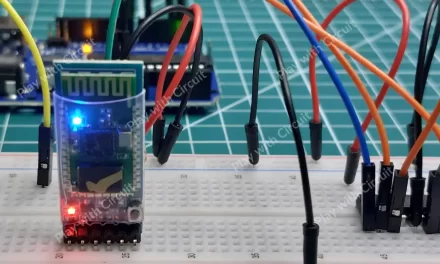
At the core of this system lies the Reyax RYLR999, a wireless communication module that integrates Bluetooth Low Energy (BLE) and LoRa technology within a single compact hardware module.
In this project, the module operates in two communication modes: BLE for short-range interaction and LoRa for long-range transmission.
- It acts as a BLE interface, allowing a smartphone to connect and send commands.
- It functions as a LoRa transceiver, forwarding those commands over long distances to another RYLR999 module.
BLE is used as the user interface layer. A smartphone connects to the module via BLE and sends appliance control commands. Once the module receives the command through its BLE interface, it processes the data and forwards those commands over long distances to another RYLR999 module.
This dual capability of the Reyax module makes it possible to transform short-range BLE commands into long-range LoRa transmissions.
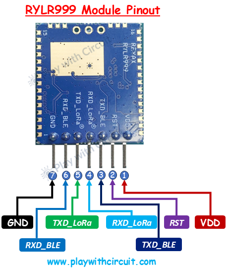
RYLR999 Pinout
The pinout of Reyax RYLR999 module is shown as follows:
| Pin | Name | Description |
|---|---|---|
| 1 | VDD | Power supply pin. The module is powered with a 5V supply. |
| 2 | RST | Reset pin. Pulling this pin LOW resets the module. |
| 3 | TXD_BLE | BLE UART transmit pin. Sends data from the BLE interface to an external device or microcontroller. |
| 4 | RXD_LoRa | LoRa UART receive pin. Used by a microcontroller to send commands to the LoRa module. |
| 5 | TXD_LoRa | LoRa UART transmit pin. LoRa module transmits data to the Arduino through this pin. |
| 6 | RXD_BLE | BLE UART receive pin. Used to send data from a microcontroller to the BLE interface. |
| 7 | GND | Ground pin |
💡Must Read
How to Interface Reyax RYLR999 LoRa Module with Arduino
Explore this tutorial to learn about the RYLR999 Module and how to interface it with Arduino UNO.
Why is Relay Required?
In this project, the microcontroller receives control commands from the RYLR999 module and must physically switch electrical appliances ON or OFF. However, microcontrollers like Arduino operate at low voltages (5V) and can only supply a small amount of current through their GPIO pins.
On the other hand, household electrical appliances operate at high-voltage AC (110V or 230V, depending on region) and may draw several amps of current. Directly connecting such loads to a microcontroller would not only damage the board but would also pose a serious safety risk.
This is where the relay becomes important. A relay acts as an electrically controlled switch. It allows a low-voltage control signal from the microcontroller to safely switch high-voltage AC or high-current DC loads. In this project, the relay forms the critical interface between the digital control system and real-world electrical devices.
Hardware Setup and Connections
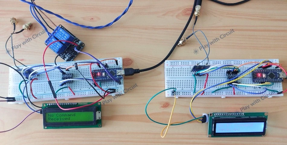
The system is divided into two main parts: a controller and a target.
On the controller side, an Android smartphone acts as the user interface. It connects to the RYLR999 module via Bluetooth Low Energy (BLE) using the LightBlue mobile application. When a user presses a button in the mobile app, a command such as turning a bulb or fan ON or OFF is transmitted to the RYLR999 module through BLE.
The Arduino Nano connected to the LoRa module reads and parses these incoming BLE commands. The Arduino then retransmits the same data to the LoRa module, which transmits the command over LoRa wireless communication.
At the target side, another RYLR999 LoRa module receives the transmitted data. This module is connected to a second Arduino Nano, which reads the incoming LoRa message and interprets the command. Based on the received instruction, the Arduino controls electrical appliances such as a 220 V AC bulb (lamp) or a 12V DC fan using a relay module.
Once the command is executed, the target also sends a confirmation message back to the controller to indicate successful operation.
The LCD provides real-time feedback about the system status during operation. It displays messages such as module initialization status, received commands from the mobile application, transmission of commands over LoRa, and confirmation responses from the target side. If a command is successfully transmitted and acknowledged, the LCD shows a confirmation message; otherwise, it displays alerts such as invalid command.
Hardware Requirement
| Components | Quantity | Remarks | Where to Buy |
|---|---|---|---|
| Arduino Nano | 2 | Microcontroller board | Amazon |
| RYLR999 Module | 2 | Converts logic levels between 5V Arduino and 3.3V LoRa module | Amazon / Digikey |
| Jumper Wires | Multiple | For connections between modules, LCD and Arduino Nano | Amazon |
| USB Cable Type A to B Mini | 1 | For providing power to 12V Fan | Amazon |
| 12V Supply Adapter | 1 | For providing power to Arduino Nano | Amazon |
| 5V Bidirectional Voltage Shifter Module | 2 | Converts logic levels between 5V Arduino and 3.3V LoRa module | Amazon |
| LCD 16x2 | 2 | I2C-based LCD used to display system status and communication messages | Amazon |
| 2 Channel Relay Module | 2 | Used to control external loads such as a 12V fan and 240V AC bulb | Amazon |
Software Requirement
- Arduino IDE, Version 2.3.4 or above installed on your PC.
- LiquidCrystal_I2C Library by Frank de Brabander V 1.1.2
Wiring Connections for the Controller Setup
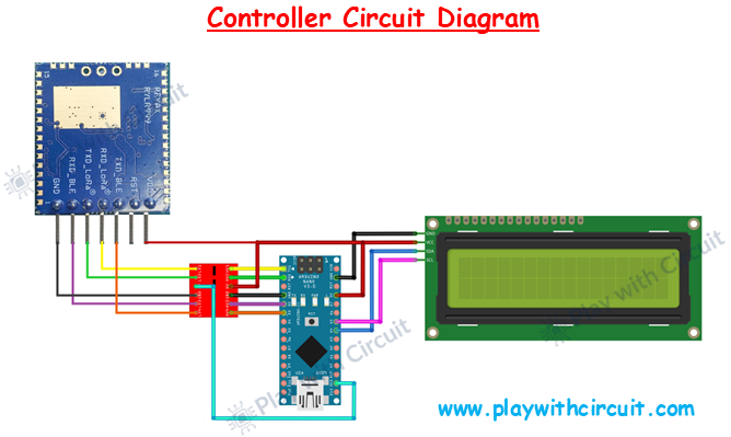
The above image shows the circuit diagram for the controller setup. The RYLR999 LoRa + BLE module is responsible for wireless communication. It communicates with the Arduino using serial communication lines. The module requires 3.3V logic levels, whereas the Arduino Nano operates at 5V logic levels. Because of this difference, a voltage level shifter is placed between the Arduino Nano and the module.
The power connections are straightforward. VDD pin of the RYLR999 is connected to the 5V output of the Arduino Nano. The GND pin of the module is connected to the Arduino’s GND.
The TXD_LORA pin of LoRa module is connected to the LV2 pin of voltage shifter and the corresponding HV2 output of voltage shifter module is connected to the Arduino’s Rx pin, while the TXD pin of Arduino is connected to the HV1 pin of voltage shifter and corresponding LV1 output is connected to RXD_LORA pin.
As Arduino has only one Serial port another serial port is created using Software, and using that we make Pin 2 and Pin 3 as BLE_TX and BLE_RX for BLE Communication.
The TXD_BLE pin of the module is connected to the LV4 pin of the voltage shifter and the corresponding HV4 output of the voltage shifter is connected to the Arduino’s BLE_RX (pin3). The BLE_TX (pin 2) of the Arduino is connected to the HV3 pin of the voltage shifter and corresponding LV3 output is connected to the RXD_BLE pin of the module.
The 5V pin of the Arduino is connected to the HV pin of the voltage shifter and 3.3V pin of Arduino is connected to the LV pin of the voltage shifter module. These power connections are important to make voltage shifter work.
The pinout of the voltage shifter module is given below:
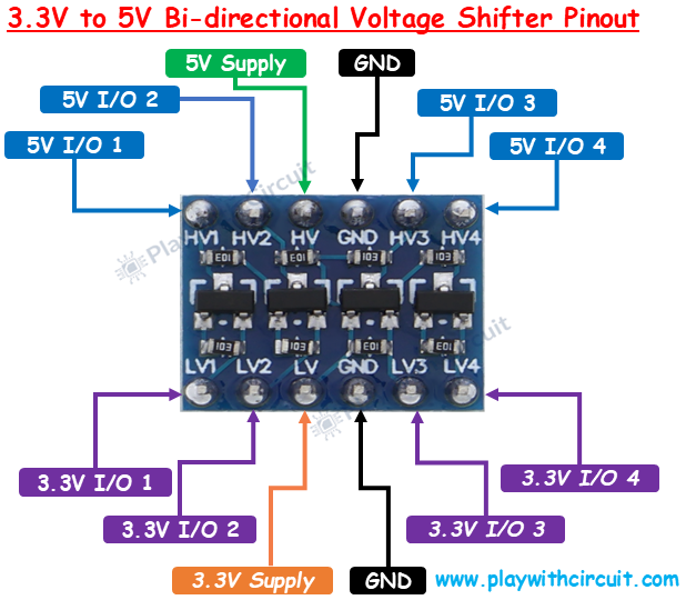
The connections between Arduino Uno and RYLR999 Module are as follows:
| Arduino Nano Pin | RYLR999 Pin | Purpose |
|---|---|---|
| 5V | VDD | Power supply to module |
| GND | GND | Common ground |
| Rx (pin 0) | TXD_LoRa (via voltage shifter) | Arduino receives data from module through LORA |
| Tx (pin 1) | RXD_LoRa (via voltage shifter) | Arduino sends data to module through LORA |
| BLE_TX (pin 2) | RXD_BLE (via voltage shifter) | Arduino sends data to module through BLE |
| BLE_RX (pin 3) | TXD_BLE (via voltage shifter) | Arduino receives data from module through BLE |
The wiring of the I2C LCD with Arduino is simple. Connect the Vcc and GND pins of I2C LCD with the Vcc and GND pins of the Arduino. SCL(clock) and SDA(data) pins of I2C LCD are connected to SCL and SDA pins of Arduino.
SCL and SDA pins are the same as pins A5 and A4 Analog input pins of Arduino where pink and blue wires are connected with LCD. These header pins are also connected to A5 and A4 pins of Arduino.
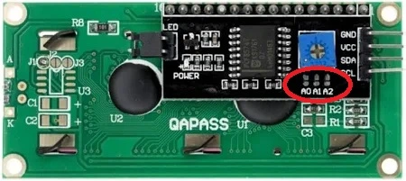
Make sure A0, A1, A2 address jumpers are not shorted when using I2C LCD. As in code we will be using Address 0x27 for the I2C LCD which will only be formed when these jumpers are not shorted in the I2C LCD.
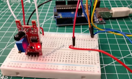
Wiring Connections for the Target Setup
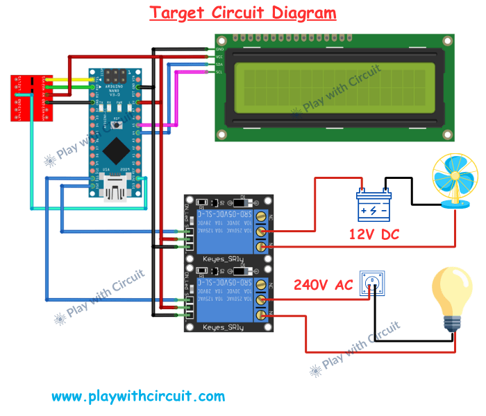
The target circuit is similar to the controller circuit, except that it doesn’t use BLE Functionality and includes an additional relay module that controls the electrical appliances fan and bulb.
The RYLR999 LoRa module communicates with the Arduino Nano using serial communication. Just like in the controller, the communication lines pass through a voltage level shifter to safely convert voltage levels between the 5V Arduino and the 3.3V LoRa module.
Here, the target module continuously listens for incoming LoRa messages transmitted by the controller through the RYLR999 module. When a message arrives, the module forwards the received data to the Arduino through the serial communication lines. The Arduino Nano interprets the received message and determines which appliance should be controlled. The Arduino then sends control signals to the relay module.
The relay module is connected to the Arduino through digital output pins. Each relay channel has an input pin that receives a control signal from the Arduino. When the Arduino activates a relay input pin, the relay switches its internal contacts, allowing it to turn an electrical appliance ON or OFF.
In the above circuit, relay channel 1, which is controlled using the D11 pin of Arduino, is used to control a bulb, while relay channel 2, which is controlled using the D12 pin of Arduino, controls a bulb.
The relay module is powered from the Arduino Nano, where the VCC pin of the relay is connected to the 5V pin of the Arduino, and the GND pin of the relay is connected to the Arduino’s GND pin. For 240V AC bulb, the relay is used to switch the live wire of the AC supply. The line from the AC source is connected to the relay’s common terminal, and the output from the normally open terminal goes to the bulb. When relay channel 1 is activated, the relay closes the circuit and allows the AC voltage to reach the bulb, turning it ON. When the relay is deactivated, the circuit opens and the bulb turns OFF.
For the 12V DC fan, the relay is placed in series with the 12V power line going to the fan. When the Arduino activates relay channel 2, the relay contacts close and allow the 12V supply to reach the fan, turning it ON. When the relay is deactivated, the circuit opens and the fan turns OFF.
This configuration allows the Arduino to control both DC and AC electrical loads safely using the relay module while keeping the high-voltage circuits isolated from the main circuit.
Just like the controller setup, the target setup also includes a 16×2 I2C LCD connected to the Arduino. This LCD displays information such as received commands and the status of appliance control.
❕Note
Since the relay controls a 240V AC load, proper electrical safety precautions must be followed while wiring the circuit. Always ensure that the AC power supply is disconnected during wiring to avoid electric shock.
Command Structure
Controller Side
On the controller side, we write the code to parse the commands sent from the BLE Mobile application.
- CMD: *L1#
To Turn Bulb ON
- CMD: *L0#
To Turn Bulb OFF
- CMD: *F1#
To Turn Fan ON
- CMD: *F0#
To Turn Fan OFF
Please note that we are not sending any response to the Light Blue BLE application, as this application is not created by us. Since the application does not receive or display responses from our system, sending a reply would serve no practical purpose. Therefore, the Arduino only reads and processes the commands sent from the app without transmitting any response back to it.
Target Side
The target will receive commands from the controller over the LoRa interface. In the target, we write the code to parse the commands sent using the LoRa.
- CMD: L1
REPLY: DONE
To Turn Bulb ON
- CMD: L0
REPLY: DONE
To Turn Bulb OFF
- CMD: F1
REPLY: DONE
To Turn Fan ON
- CMD: F0
REPLY: DONE
To Turn Fan OFF
Please note that here we are showing only the actual command payload and response payload for simplicity. However, the data transmitted by the LoRa module is not limited to just this payload.
When using the RYLR999 LoRa module, additional information must be included in the transmission command, such as the destination device address, payload length, and other protocol-specific characters required by the module’s AT command format. These fields are necessary for the module to correctly identify the target and transmit the data properly over LoRa communication.
Arduino Code for Controller
This program receives commands from a mobile application via Bluetooth using the Bluetooth functionality of the RYLR999 LoRa module. Once a command is received, the Arduino validates the command and only after validation, it forwards that command to another Arduino (Target) using LoRa communication through the same module. The complete communication process is displayed on a 16×2 I2C LCD.
 /*
Code to receive commands from Mobile device using bluetooth functionality of RLY999 module and send these commands from one Arduino to another Arduino using LORA functionality of RYL999 Module and display complete communication on I2C LCD
by playwithcircuit.com
*/
#include <LiquidCrystal_I2C.h>
#include <SoftwareSerial.h>

// below MACROS are for LORA communication
#define REPLY_TIMEOUT_IN_MS 300
#define REPLY_END_CHAR '\n'
#define SELF_ADDRESS 0
#define TARGET_ADDRESS 1
#define MIN_CHAR_TO_RCV 1
#define WAIT_FOR_TARGET_REPLY 3000

// below MACROS and strings are for Bluetooth communication
#define START_CHAR_BT_COMM '*'
#define END_CHAR_BT_COMM '#'
#define START_CHAR_TIME_OUT_BT_COMM (3000U)  // time in ms
#define END_CHAR_TIME_OUT_BT_COMM (300U)      // time in ms

// these four strings can be received from bluetooth Rx pin which are transmitted by the mobile application
String sCMDLampON = "L1";
String sCMDLampOFF = "L0";
String sCMDFanON = "F1";
String sCMDFanOFF = "F0";

// save received command in this global string object
String receivedCommand;

// initialize softserial port at pin 3(Rx) and 2(Tx)
SoftwareSerial btSerial(3, 2);

// Init LCD at 0x27, 16x2
LiquidCrystal_I2C lcd(0x27, 16, 2);

void setup() {
  boolean boRetVal = false;
  // begin serial communication at baud 115200,n,8,1
  // to communicate with the LORA functionality of module
  Serial.begin(115200);
  // begin soft serial communication at baud 115200,n,8,1
  // to communicate with the Bluetooth functionality of module
  btSerial.begin(115200);
  btSerial.setTimeout(END_CHAR_TIME_OUT_BT_COMM);  // set time out for readStringUntil() function

  // Initialize the LCD
  lcd.init();
  // Turn ON the Backlight
  lcd.backlight();
  // Clear the display buffer
  lcd.clear();

  receivedCommand.reserve(50);  // prevents fragmentation, as multiple times data shall be received in this string

  // clear receive buffer of LORA
  flushBuffer();  // clear rx data

  // Reset settings to factory defaults for LORA functionality
  boRetVal = boRestoreFactoryDefaults();

  // setting the address of LORA
  if (boRetVal == true) {
    flushBuffer();  // clear rx data
    boRetVal = boSetAddress();
  }

  if (boRetVal == true) {
    lcd.clear();
    lcd.setCursor(0, 0);
    lcd.print("Module Init");
    lcd.setCursor(0, 1);
    lcd.print("Successful");
    delay(1000);
  } else {
    lcd.clear();
    lcd.setCursor(0, 0);
    lcd.print("Module Init");
    lcd.setCursor(0, 1);
    lcd.print("Failed");
    while (1)
      ;
  }
}

void loop() {
  String expected_reply = "DONE";
  bool boRetVal = false;

  flushBuffer();  // clear rx data

  // get commands using BT functionality using Mobile Application
  boRetVal = rcvCommand(START_CHAR_TIME_OUT_BT_COMM);

  if (boRetVal == false) {
    // Displaying Failed Msg
    lcd.clear();
    lcd.setCursor(0, 0);
    lcd.print("No BT Command");
    lcd.setCursor(0, 1);
    lcd.print("Received");
  } else {
    // check if valid command is received
    if ((receivedCommand == sCMDLampON) || (receivedCommand == sCMDLampOFF) || (receivedCommand == sCMDFanON) || (receivedCommand == sCMDFanOFF)) {
      // transmits receivedCommand
      boRetVal = boSendData(receivedCommand);
      if (boRetVal == true) {
        // Displaying Sent Msg
        lcd.clear();
        lcd.setCursor(0, 0);
        lcd.print("Cmd Rcvd & Sent");
        lcd.setCursor(0, 1);
        lcd.print(receivedCommand);
        delay(1000);
        boRetVal = chkReply(expected_reply, REPLY_END_CHAR, WAIT_FOR_TARGET_REPLY);

        if (boRetVal == true) {
          // Displaying received Msg
          lcd.clear();
          lcd.setCursor(0, 0);
          lcd.print("Reply Received:");
          lcd.setCursor(0, 1);
          lcd.print(expected_reply);
        } else {
          lcd.clear();
          lcd.setCursor(0, 0);
          lcd.print("No Reply");
          lcd.setCursor(0, 1);
          lcd.print("Received");
        }
      } else {
        // Displaying Failed Msg
        lcd.clear();
        lcd.setCursor(0, 0);
        lcd.print("Command");
        lcd.setCursor(0, 1);
        lcd.print("Sending Failed");
      }
    } else {
      // Displaying Invalid Msg
      lcd.clear();
      lcd.setCursor(0, 0);
      lcd.print("Invalid:");
      lcd.print(receivedCommand);
      lcd.setCursor(0, 1);
      lcd.print("Command Received");
    }
  }
}
/******************************************** Function Definition Related to LORA Functionality ***********************/

void sendCrLf(void) {
  Serial.write(0x0D);  // Carriage Return
  Serial.write(0x0A);  // Line Feed
}

// clear receive buffer of LORA
void flushBuffer(void) {
  while (Serial.available() > 0) {
    Serial.read();
  }
}

// check data on rx pin of LORA functionality
bool chkReply(String chkString, char receiveUntil, unsigned int timeout) {
  String receivedString;       // save received data in this string object
  bool boReturnValue = false;  // function's return value

  // wait for reply
  do {
    timeout--;
    delay(1);  // delay of 1 ms
  } while ((Serial.available() < MIN_CHAR_TO_RCV) && (timeout > 0));

  if (timeout) {
    // if timeout is left then a reply is received check for the string in the reply
    receivedString = Serial.readStringUntil(receiveUntil);
    if (receivedString.indexOf(chkString) != -1) {
      boReturnValue = true;
    } else {
      boReturnValue = false;
    }
  } else {
    boReturnValue = false;
  }

  // return result
  return boReturnValue;
}

// Reset settings to factory defaults for LORA functionality
bool boRestoreFactoryDefaults(void) {
  const char factoryDefaultCmd[] = "AT+FACTORY";  // command to be sent
  bool boReturnValue = false;                     // function's return value
  char downCounter = 100;                         // Down counter to wait for reply
  String receivedString;                          // save received data in this string object

  String chkRcvString1 = "+FACTORY";
  String chkRcvString2 = "+READY";

  // send command
  Serial.print(factoryDefaultCmd);
  sendCrLf();

  // check first string in reply
  boReturnValue = chkReply(chkRcvString1, REPLY_END_CHAR, REPLY_TIMEOUT_IN_MS);
  if (boReturnValue == true) {
    // check second string in reply
    boReturnValue = chkReply(chkRcvString2, REPLY_END_CHAR, REPLY_TIMEOUT_IN_MS);
  }

  // return result
  return boReturnValue;
}

// setting the address of LORA
bool boSetAddress(void) {
  const char setAddressCmd[] = "AT+ADDRESS=";  // command to be sent
  bool boReturnValue = false;                  // function's return value
  String chkRcvString = "+OK";

  // send command
  Serial.print(setAddressCmd);
  Serial.print(SELF_ADDRESS);
  sendCrLf();

  // check reply
  boReturnValue = chkReply(chkRcvString, REPLY_END_CHAR, REPLY_TIMEOUT_IN_MS);

  // return result
  return boReturnValue;
}

// Send data to LORA in command form
bool boSendData(String data) {
  const char sendDataCmd[] = "AT+SEND=";  // command to be sent
  bool boReturnValue = false;             // function's return value
  String chkRcvString = "+OK";

  // send command
  Serial.print(sendDataCmd);
  Serial.print(TARGET_ADDRESS);
  Serial.print(',');
  Serial.print(data.length());
  Serial.print(',');
  Serial.print(data);
  sendCrLf();

  // check reply
  boReturnValue = chkReply(chkRcvString, REPLY_END_CHAR, REPLY_TIMEOUT_IN_MS);

  // return result
  return boReturnValue;
}

/******************************************** Function Definition Related to BT Functionality *************************/

// Receive Command from Rx pin of Bluetooth functionality
bool rcvCommand(unsigned int timeout) {
  bool boReturnValue = false;  // function's return value
  unsigned long startTime;

  // wait for reply
  do {
    timeout--;
    delay(1);  // delay of 1 ms
    if (((btSerial.available() >= MIN_CHAR_TO_RCV) && (btSerial.read() == START_CHAR_BT_COMM)) || (timeout == 0)) {
      break;
    }
  } while (1);

  // if start character is received within time then timeout will be greater than or equal to 1
  if (timeout) {
    startTime = millis();
    receivedCommand = btSerial.readStringUntil(END_CHAR_BT_COMM);
    if ((millis() - startTime) <= END_CHAR_TIME_OUT_BT_COMM) {
      boReturnValue = true;  // it means in readStringUntil() function '#' is received
    } else {
      boReturnValue = false;  // it means in readStringUntil() function timeout has occurred
    }
  } else {
    boReturnValue = false;  // it means get character timeout has occured
  }

  // return result
  return boReturnValue;
}
Code Explanation
Including Required Libraries
The program begins by including two libraries. The LiquidCrystal_I2C.h library is used to control the I2C LCD display.
The SoftwareSerial library creates a secondary serial interface that allows the Arduino to communicate with the Bluetooth functionality of the RYLR999 module using custom digital pins.
#include <LiquidCrystal_I2C.h>
#include <SoftwareSerial.h>
Defining LoRa Communication Parameters
Now we define parameters used for LoRa communication. These parameters control how the Arduino communicates with the LoRa module.
REPLY_TIMEOUT_IN_MSdefines the maximum time (in milliseconds) the Arduino will wait for a reply from the LoRa module after sending a command. In this case, the Arduino will wait 300 milliseconds for a response.REPLY_END_CHARdefines the character that marks the end of a message received from the LoRa module.SELF_ADDRESSdefines the unique address of the current LoRa node. Here, the current device has the address 0.TARGET_ADDRESSspecifies the address of the remote LoRa node that will receive the transmitted message. Here the target node has the address 1.MIN_CHAR_TO_RCVdefines the minimum number of characters required before reading serial data. Setting this value to 1 ensures that the program waits until at least one character is received before attempting to read the message.WAIT_FOR_TARGET_REPLYdetermines how long the Arduino waits for a response from the target node.
Each LoRa node must have a unique address to ensure proper communication.
// below MACROS are for LORA communication
#define REPLY_TIMEOUT_IN_MS 300
#define REPLY_END_CHAR '\n'
#define SELF_ADDRESS 0
#define TARGET_ADDRESS 1
#define MIN_CHAR_TO_RCV 1
#define WAIT_FOR_TARGET_REPLY 3000
Defining Bluetooth Communication Parameters
Now we define macros that configure how commands are received through Bluetooth. The mobile application sends commands in a specific format.
For example: *L1#, where * marks the start of the command and # marks the end of the command
The timeout values ensure that the Arduino does not wait indefinitely if the command is incomplete or corrupted.
// below MACROS and strings are for Bluetooth communication
#define START_CHAR_BT_COMM '*'
#define END_CHAR_BT_COMM '#'
#define START_CHAR_TIME_OUT_BT_COMM (3000U)  // time in ms
#define END_CHAR_TIME_OUT_BT_COMM (300U)      // time in ms
Defining Supported Commands
Here we define four valid commands that can be received from the mobile application. These commands represent device control operations:
L1 → Turn Bulb ON
L0 → Turn Bulb OFF
F1 → Turn Fan ON
F0 → Turn Fan OFF
The received command is then stored in the global string.
// these four strings can be received from bluetooth Rx pin which are transmitted by the mobile application
String sCMDLampON = "L1";
String sCMDLampOFF = "L0";
String sCMDFanON = "F1";
String sCMDFanOFF = "F0";
// save received command in this global string object
String receivedCommand;
Creating Communication Objects
Here we create a SoftwareSerial object named btSerial. The SoftwareSerial library allows the Arduino to create an additional serial communication port using digital pins instead of the hardware serial pins. Here, this software serial port is used for BLE communication.
Here we define Pin 3 as RX (Receive pin of Arduino) and Pin 2 as TX (Transmit pin of Arduino).
This allows us to keep the hardware serial pins (D0 and D1) free for communicating with the RYLR999 module.
Next, we create an object named lcd for controlling the 16×2 I2C LCD display using the LiquidCrystal_I2C library. The configuration of the display is:
- I2C address: 0x27
- Display size: 16 columns × 2 rows
// initialize softserial port at pin 3(Rx) and 2(Tx)
SoftwareSerial btSerial(3, 2);

// Init LCD at 0x27, 16x2
LiquidCrystal_I2C lcd(0x27, 16, 2);
Setup Function
The setup() function initializes all hardware components and configures the LoRa module.
First, a Boolean variable boRetVal is declared and initialized to false. This variable is later used to store the success or failure status of certain operations performed during initialization.
Next, the Arduino begins serial communication at a baud rate of 115200 using the Serial.begin() command. This serial interface is used to communicate with the LoRa functionality of the RYLR999 module, allowing the Arduino to send AT commands and receive responses from the module.
After that, the SoftwareSerial communication is started using btSerial.begin(). Next, we set a timeout for the readStringUntil() function, ensuring that the Arduino does not wait indefinitely if the end character of a command is not received.
void setup() {
  boolean boRetVal = false;
  // begin serial communication at baud 115200,n,8,1
  // to communicate with the LORA functionality of module
  Serial.begin(115200);
  // begin soft serial communication at baud 115200,n,8,1
  // to communicate with the Bluetooth functionality of module
  btSerial.begin(115200);
  btSerial.setTimeout(END_CHAR_TIME_OUT_BT_COMM);  // set time out for readStringUntil() function
Next, we initialize the 16×2 I2C LCD. The lcd.init() function prepares the LCD for operation, lcd.backlight() turns on the display backlight, and lcd.clear() clears any previous data from the screen. This ensures that the LCD starts with a clean display.
  // Initialize the LCD
  lcd.init();
  // Turn ON the Backlight
  lcd.backlight();
  // Clear the display buffer
  lcd.clear();
Next we allocate memory for the receivedCommand string in advance. Since this string will be used repeatedly to store commands received from the BLE mobile application, reserving memory helps prevent memory fragmentation in the Arduino’s limited RAM. By reserving space for up to 50 characters, the program avoids repeatedly reallocating memory during runtime.
Next, the function flushBuffer() is called to clear any leftover data in the serial receive buffer of the LoRa module. Clearing the buffer helps prevent incorrect data from interfering with the next command or response.
Next, we reset the LoRa functionality of the RYLR999 module to its factory default settings. This step ensures that the module starts with a known and stable configuration before further setup commands are executed. The result of this operation is stored in the variable boRetVal, which indicates whether the reset was successful or not.
  receivedCommand.reserve(50);
// prevents fragmentation, as multiple times data shall be received in this string

  // clear receive buffer of LORA
  flushBuffer();  // clear rx data

  // Reset settings to factory defaults for LORA functionality
  boRetVal = boRestoreFactoryDefaults();
The program now checks whether the reset operation was successful by evaluating the value of boRetVal. If the reset was successful (boRetVal == true), the serial buffer is cleared again using flushBuffer().
Next, the function boSetAddress() is called to assign a unique address to the LoRa module. This address is used to identify the device during communication.
The program again checks the value of boRetVal to determine whether the initialization process was completed successfully.
If the initialization is successful, the LCD displays “Module Init Successful” to inform the user that the LoRa module has been configured correctly. A short delay is added so that the message remains visible on the screen.
If the initialization fails, the LCD displays “Module Init Failed”. The program then enters an infinite loop using while(1); which stops further execution of the program.
// setting the address of LORA
  if (boRetVal == true) {
    flushBuffer();  // clear rx data
    boRetVal = boSetAddress();
  }

  if (boRetVal == true) {
    lcd.clear();
    lcd.setCursor(0, 0);
    lcd.print("Module Init");
    lcd.setCursor(0, 1);
    lcd.print("Successful");
    delay(1000);
  } else {
    lcd.clear();
    lcd.setCursor(0, 0);
    lcd.print("Module Init");
    lcd.setCursor(0, 1);
    lcd.print("Failed");
    while (1)
      ;
  }
}
loop() Function
The loop() function is responsible for receiving commands from the mobile application through BLE, validating them, transmitting them over LoRa, and updating the LCD with the system status.
At the beginning of the loop, we define a string variable expected_reply with the value “DONE”. This is the confirmation message expected from the target side after it successfully executes a command.
Then, we initialize the boolean variable boRetVal to false. This variable is used to store the success or failure status of operations performed in the loop, such as receiving commands or sending data.
Next, we clear the LoRa serial buffer using the flushBuffer() function.
We use rcvCommand() to receive commands sent from the mobile application through the BLE interface of the RYLR999 module. The function waits for a command within the specified timeout period. If a command is successfully received and parsed, the function returns true; otherwise, it returns false.
If no command is received within the allowed time, the LCD displays the message “No BT Command Received”. This indicates that the system did not receive any input from the mobile application.
If a command is received, the program checks whether it matches one of the valid predefined commands:
- L1 → Bulb ON
- L0 → Bulb OFF
- F1 → Fan ON
- F0 → Fan OFF
Only these commands are accepted.
If the command is valid, the Arduino sends it to the target through the LoRa communication interface using the boSendData() function.
If the command is successfully transmitted, the LCD displays “Cmd Rcvd & Sent” along with the command that was received.
void loop() {
  String expected_reply = "DONE";
  bool boRetVal = false;

  flushBuffer();  // clear rx data

  // get commands using BT functionality using Mobile Application
  boRetVal = rcvCommand(START_CHAR_TIME_OUT_BT_COMM);

  if (boRetVal == false) {
    // Displaying Failed Msg
    lcd.clear();
    lcd.setCursor(0, 0);
    lcd.print("No BT Command");
    lcd.setCursor(0, 1);
    lcd.print("Received");
  } else {
    // check if valid command is received
    if ((receivedCommand == sCMDLampON) || (receivedCommand == sCMDLampOFF) || (receivedCommand == sCMDFanON) || (receivedCommand == sCMDFanOFF)) {
      // transmits receivedCommand
      boRetVal = boSendData(receivedCommand);
      if (boRetVal == true) {
        // Displaying Sent Msg
        lcd.clear();
        lcd.setCursor(0, 0);
        lcd.print("Cmd Rcvd & Sent");
        lcd.setCursor(0, 1);
        lcd.print(receivedCommand);
        delay(1000);
After the command is successfully transmitted through LoRa, the Arduino waits for a confirmation message from the target. The function chkReply() listens for incoming data from the LoRa module and checks whether the expected reply string “DONE” is received within the specified timeout period. If the correct reply is detected, the function returns true; otherwise, it returns false.
If the expected confirmation message is received from the target unit, the LCD displays “Reply Received:” on the first line and shows the reply message (in this case, “DONE”) on the second line.
If no response is received, the LCD displays “No Reply Received”.
  boRetVal = chkReply(expected_reply, REPLY_END_CHAR, WAIT_FOR_TARGET_REPLY);

        if (boRetVal == true) {
          // Displaying received Msg
          lcd.clear();
          lcd.setCursor(0, 0);
          lcd.print("Reply Received:");
          lcd.setCursor(0, 1);
          lcd.print(expected_reply);
        } else {
          lcd.clear();
          lcd.setCursor(0, 0);
          lcd.print("No Reply");
          lcd.setCursor(0, 1);
          lcd.print("Received");
        }
If the command could not be transmitted through the LoRa module, the LCD displays “Command Sending Failed”.
If the received command from the mobile application does not match any of the predefined valid commands, it is considered invalid. In this case, the LCD displays “Invalid:” followed by the received command on the first line and “Command Received” on the second line. This helps the user identify incorrect commands sent from the mobile application.
 } else {
        // Displaying Failed Msg
        lcd.clear();
        lcd.setCursor(0, 0);
        lcd.print("Command");
        lcd.setCursor(0, 1);
        lcd.print("Sending Failed");
      }
    } else {
      // Displaying Invalid Msg
      lcd.clear();
      lcd.setCursor(0, 0);
      lcd.print("Invalid:");
      lcd.print(receivedCommand);
      lcd.setCursor(0, 1);
      lcd.print("Command Received");
    }
  }
}
Functions Related to LoRa Communication
The following functions are used to manage communication between the Arduino Nano and the RYLR999 LoRa module.
sendCrLf() Function sends a Carriage Return (CR) and Line Feed (LF) character to the LoRa module through the serial interface. These characters are required at the end of every AT command sent to the RYLR999 module.
flushBuffer() Function clears the serial receive buffer used for LoRa communication.
chkReply() Function checks whether a specific reply is received from the LoRa module within a defined time period. First, the function waits until at least one character becomes available in the serial buffer. The waiting process is controlled using a loop that decreases the timeout value every millisecond.
If data becomes available before the timeout expires, the function reads the incoming message using readStringUntil().
The received message is then checked to see whether it contains the expected string stored in chkString. If the expected text is found, the function returns true, indicating that the correct reply was received. Otherwise, it returns false.
void sendCrLf(void) {
  Serial.write(0x0D);  // Carriage Return
  Serial.write(0x0A);  // Line Feed
}

// clear receive buffer of LORA
void flushBuffer(void) {
  while (Serial.available() > 0) {
    Serial.read();
  }
}

// check data on rx pin of LORA functionality
bool chkReply(String chkString, char receiveUntil, unsigned int timeout) {
  String receivedString;       // save received data in this string object
  bool boReturnValue = false;  // function's return value

  // wait for reply
  do {
    timeout--;
    delay(1);  // delay of 1 ms
  } while ((Serial.available() < MIN_CHAR_TO_RCV) && (timeout > 0));

  if (timeout) {
    // if timeout is left then a reply is received check for the string in the reply
    receivedString = Serial.readStringUntil(receiveUntil);
    if (receivedString.indexOf(chkString) != -1) {
      boReturnValue = true;
    } else {
      boReturnValue = false;
    }
  } else {
    boReturnValue = false;
  }

  // return result
  return boReturnValue;
}
Next, we define the function to reset the RYLR999 module to its factory default configuration using AT command AT+FACTORY. The function declares a few variables for this process.
boReturnValue stores the result of the function (success or failure).
downCounter acts as a small counter while waiting for replies from the module.
receivedString is used to store any incoming response from the LoRa module.
When the module receives the reset command, it typically responds with two messages:
- The first message, “+FACTORY” – indicates that the reset command has been accepted.
- The second message, “+READY” – indicates that the module has completed the reset and is ready to operate.
Next, the command AT+FACTORY is sent to the module through the serial interface. The sendCrLf() function then sends the required carriage return and line feed characters, which signal the end of the AT command.
The program then waits for the first response “+FACTORY” using the chkReply() function to confirm that the reset command was received.
If the response is received, the program then waits for the second message “+READY”, which confirms that the reset process has completed.
Finally, the function returns the value of boReturnValue. If both responses are received successfully, the function returns true, indicating that the LoRa module was reset properly. Otherwise, it returns false.
// Reset settings to factory defaults for LORA functionality
bool boRestoreFactoryDefaults(void) {
  const char factoryDefaultCmd[] = "AT+FACTORY";  // command to be sent
  bool boReturnValue = false;                     // function's return value
  char downCounter = 100;                         // Down counter to wait for reply
  String receivedString;                          // save received data in this string object

  String chkRcvString1 = "+FACTORY";
  String chkRcvString2 = "+READY";

  // send command
  Serial.print(factoryDefaultCmd);
  sendCrLf();

  // check first string in reply
  boReturnValue = chkReply(chkRcvString1, REPLY_END_CHAR, REPLY_TIMEOUT_IN_MS);
  if (boReturnValue == true) {
    // check second string in reply
    boReturnValue = chkReply(chkRcvString2, REPLY_END_CHAR, REPLY_TIMEOUT_IN_MS);
  }

  // return result
  return boReturnValue;
}
We use the function boSetAddress() to assign a unique address to the RYLR999 module.
The command AT+ADDRESS= is used to configure the module address. The Arduino sends this command through the serial interface along with the value defined by SELF_ADDRESS. After sending the command, the function sendCrLf() adds the required carriage return and line feed characters.
After sending the command, the program waits for the module’s response. If the module responds with “+OK”, it means the address has been configured successfully. The function returns true if the correct response was received, otherwise it returns false.
// setting the address of LORA
bool boSetAddress(void) {
  const char setAddressCmd[] = "AT+ADDRESS=";  // command to be sent
  bool boReturnValue = false;                  // function's return value
  String chkRcvString = "+OK";

  // send command
  Serial.print(setAddressCmd);
  Serial.print(SELF_ADDRESS);
  sendCrLf();

  // check reply
  boReturnValue = chkReply(chkRcvString, REPLY_END_CHAR, REPLY_TIMEOUT_IN_MS);

  // return result
  return boReturnValue;
}
Sending Data Through LoRa
We use boSendData to send a message to another LoRa node.
The LoRa module requires the AT+SEND command to transmit data. This command includes three important parameters: the target’s address, the length of the data, and the actual message to be transmitted.
The Arduino constructs this command by printing AT+SEND= followed by the target’s address (TARGET_ADDRESS), the length of the message (data.length()), and the message content itself. These values are separated by commas.
After forming the complete command, the Arduino sends it to the module through the serial interface and calls the sendCrLf() function to terminate the command properly.
The program then waits for the module’s response using the chkReply() function. If the module returns “+OK”, it indicates that the data was transmitted successfully. In that case, the function returns true; otherwise, it returns false, indicating that the transmission failed.
// Send data to LORA in command form
bool boSendData(String data) {
  const char sendDataCmd[] = "AT+SEND=";  // command to be sent
  bool boReturnValue = false;             // function's return value
  String chkRcvString = "+OK";

  // send command
  Serial.print(sendDataCmd);
  Serial.print(TARGET_ADDRESS);
  Serial.print(',');
  Serial.print(data.length());
  Serial.print(',');
  Serial.print(data);
  sendCrLf();

  // check reply
  boReturnValue = chkReply(chkRcvString, REPLY_END_CHAR, REPLY_TIMEOUT_IN_MS);

  // return result
  return boReturnValue;
}
Receiving Commands from Bluetooth
rcvCommand is used to receive commands sent from the mobile application through the BLE interface of the RYLR999 module. It checks whether a valid command has been received within the specified timeout period.
The function returns true if a complete command is received successfully, otherwise it returns false.
Next, we declare a few variables:
boReturnValuestores the result of the function.startTimeis used to measure the time taken to receive the command, which helps detect timeout conditions.
The function first waits for the start character of a command. The loop continuously checks the Bluetooth serial buffer until the start character (*) is detected, or the timeout period expires.
If the start character is detected before the timeout expires, the program begins reading the command. The function readStringUntil() reads incoming data from the Bluetooth serial interface until the end character (#) is received.
The received data is stored in the variable receivedCommand.
If the end character (#) is received within the specified timeout, the command is considered valid and boReturnValue is set to true.
If the end character is not received within the specified time, the command is considered incomplete, and the function returns false.
Finally, the function returns the value of boReturnValue. It returns true if a valid command was received and false if no command was received.
// Receive Command from Rx pin of Bluetooth functionality
bool rcvCommand(unsigned int timeout) {
  bool boReturnValue = false;  // function's return value
  unsigned long startTime;

  // wait for reply
  do {
    timeout--;
    delay(1);  // delay of 1 ms
    if (((btSerial.available() >= MIN_CHAR_TO_RCV) && (btSerial.read() == START_CHAR_BT_COMM)) || (timeout == 0)) {
      break;
    }
  } while (1);

  // if start character is received within time then timeout will be greater than or equal to 1
  if (timeout) {
    startTime = millis();
    receivedCommand = btSerial.readStringUntil(END_CHAR_BT_COMM);
    if ((millis() - startTime) <= END_CHAR_TIME_OUT_BT_COMM) {
      boReturnValue = true;  // it means in readStringUntil() function '#' is received
    } else {
      boReturnValue = false;  // it means in readStringUntil() function timeout has occurred
    }
  } else {
    boReturnValue = false;  // it means get character timeout has occured
  }

  // return result
  return boReturnValue;
}
Arduino Code for Target
In this code, the target Arduino receives the commands over LoRa and controls the electrical appliances as per commands received using relay module.
/*
Code to receive commands to control the appliances from another Arduino using RLYR999 Module and send "DONE" in reply after implementing the required task and display the communication and tasks over I2C LCD.
by playwithcircuit.com
*/
#include <LiquidCrystal_I2C.h>

// below MACROS are for LORA communication
#define REPLY_TIMEOUT_IN_MS 300
#define REPLY_END_CHAR '\n'
#define CMD_END_CHAR '\n'
#define MODULE_ADDRESS 1
#define CONTROLLER_ADDRESS 0
#define MIN_CHAR_TO_RCV 1
#define WAIT_FOR_REQUEST 3000

// these four commands can be received from controller module
String sCMDLampON = "L1";
String sCMDLampOFF = "L0";
String sCMDFanON = "F1";
String sCMDFanOFF = "F0";

// save received command in this global string object
String receivedCommand;

// Init LCD at 0x27, 16x2
LiquidCrystal_I2C lcd(0x27, 16, 2);

// Appliance Control MACROS
#define LAMP_CTRL_PIN 11
#define FAN_CTRL_PIN 12

#define LAMP_ON() digitalWrite(LAMP_CTRL_PIN, 0)
#define LAMP_OFF() digitalWrite(LAMP_CTRL_PIN, 1)
#define FAN_ON() digitalWrite(FAN_CTRL_PIN, 0)
#define FAN_OFF() digitalWrite(FAN_CTRL_PIN, 1)

void setup() {
  boolean boRetVal = false;
  // begin serial communication at baud 115200,n,8,1
  // to communicate with the RF module
  Serial.begin(115200);

  // Initialize the LCD
  lcd.init();
  // Turn ON the Backlight
  lcd.backlight();
  // Clear the display buffer
  lcd.clear();

  // initialize appliances pins and turn off
  pinMode(LAMP_CTRL_PIN, OUTPUT);
  pinMode(FAN_CTRL_PIN, OUTPUT);
  LAMP_OFF();
  FAN_OFF();

  receivedCommand.reserve(50);  // prevents fragmentation, as multiple times data shall be received in this string

  delay(1000);

  flushBuffer();  // clear rx data

  // Reset settings to factory defaults
  boRetVal = boRestoreFactoryDefaults();

  // setting the address if reset successfully
  if (boRetVal == true) {
    flushBuffer();  // clear rx data
    boRetVal = boSetAddress();
  }

  if (boRetVal == true) {
    lcd.clear();
    lcd.setCursor(0, 0);
    lcd.print("Module Init");
    lcd.setCursor(0, 1);
    lcd.print("Successful");
    delay(1000);
  } else {
    lcd.clear();
    lcd.setCursor(0, 0);
    lcd.print("Module Init");
    lcd.setCursor(0, 1);
    lcd.print("Failed");
    while (1)
      ;
  }
}

void loop() {
  String expected_reply = "DONE";
  bool boRetVal = false;

  // check string sent by controller
  boRetVal = rcvCommand(CMD_END_CHAR, WAIT_FOR_REQUEST);

  if (boRetVal == false) {
    // Displaying Failed Msg
    lcd.clear();
    lcd.setCursor(0, 0);
    lcd.print("No Command");
    lcd.setCursor(0, 1);
    lcd.print("Received");
  } else {
    // check if valid command is received
    if ((receivedCommand == sCMDLampON) || (receivedCommand == sCMDLampOFF) || (receivedCommand == sCMDFanON) || (receivedCommand == sCMDFanOFF)) {
      // Implement receivedCommand
      vImplementTask(receivedCommand);
      // Displaying Sent Msg
      lcd.clear();
      lcd.setCursor(0, 0);
      lcd.print("Command Received");
      lcd.setCursor(0, 1);
      lcd.print("Task Done");
      delay(1000);
      // transmits receivedCommand
      boRetVal = boSendData(expected_reply);
      if (boRetVal == true) {
        // Displaying Sent Msg
        lcd.clear();
        lcd.setCursor(0, 0);
        lcd.print("Reply Sent");
      } else {
        // Displaying Failed Msg
        lcd.clear();
        lcd.setCursor(0, 0);
        lcd.print("Reply");
        lcd.setCursor(0, 1);
        lcd.print("Sending Failed");
      }
      delay(1000);
    } else {
      // Displaying Invalid Msg
      lcd.clear();
      lcd.setCursor(0, 0);
      lcd.print("Invalid:");
      lcd.print(receivedCommand);
      lcd.setCursor(0, 1);
      lcd.print("Command Received");
    }
  }
}

void sendCrLf(void) {
  Serial.write(0x0D);  // Carriage Return
  Serial.write(0x0A);  // Line Feed
}

void flushBuffer(void) {
  while (Serial.available() > 0) {
    Serial.read();
  }
}

bool rcvCommand(char receiveUntil, unsigned int timeout) {
  bool boReturnValue = false;  // function's return value
  unsigned long startTime;
  int firstComma;
  int secondComma;
  int thirdComma;
  String data;
  // wait for reply
  do {
    timeout--;
    delay(1);  // delay of 1 ms
  } while ((Serial.available() < MIN_CHAR_TO_RCV) && (timeout > 0));

  if (timeout) {
    startTime = millis();
    // if timeout is left then a reply is received check for the string in the reply
    data = Serial.readStringUntil(receiveUntil);
    if ((millis() - startTime) <= timeout) {
      boReturnValue = true;  // it means in readStringUntil() function receiveUntil character is received
      // as the data will be in form of "+RCV=0,2,F1,-88,11" we need to extract command between second and third comma
      firstComma = data.indexOf(',');
      secondComma = data.indexOf(',', firstComma + 1);
      thirdComma = data.indexOf(',', secondComma + 1);
      // extract value between 2nd and 3rd comma
      receivedCommand = data.substring(secondComma + 1, thirdComma);
    } else {
      boReturnValue = false;  // it means in readStringUntil() function timeout has occurred
    }
  } else {
    boReturnValue = false;  // it means get character timeout has occured
  }

  // return result
  return boReturnValue;
}

bool chkReply(String chkString, char receiveUntil, unsigned int timeout) {
  String receivedString;       // save received data in this string object
  bool boReturnValue = false;  // function's return value

  // wait for reply
  do {
    timeout--;
    delay(1);  // delay of 1 ms
  } while ((Serial.available() < MIN_CHAR_TO_RCV) && (timeout > 0));

  if (timeout) {
    // if timeout is left then a reply is received check for the string in the reply
    receivedString = Serial.readStringUntil(receiveUntil);
    if (receivedString.indexOf(chkString) != -1) {
      boReturnValue = true;
    } else {
      boReturnValue = false;
    }
  } else {
    boReturnValue = false;
  }

  // return result
  return boReturnValue;
}

bool boRestoreFactoryDefaults(void) {
  const char factoryDefaultCmd[] = "AT+FACTORY";  // command to be sent
  bool boReturnValue = false;                     // function's return value
  char downCounter = 100;                         // Down counter to wait for reply
  String receivedString;                          // save received data in this string object

  String chkRcvString1 = "+FACTORY";
  String chkRcvString2 = "+READY";

  // send command
  Serial.print(factoryDefaultCmd);
  sendCrLf();

  // check first string in reply
  boReturnValue = chkReply(chkRcvString1, REPLY_END_CHAR, REPLY_TIMEOUT_IN_MS);
  if (boReturnValue == true) {
    // check second string in reply
    boReturnValue = chkReply(chkRcvString2, REPLY_END_CHAR, REPLY_TIMEOUT_IN_MS);
  }

  // return result
  return boReturnValue;
}

bool boSetAddress(void) {
  const char setAddressCmd[] = "AT+ADDRESS=";  // command to be sent
  bool boReturnValue = false;                  // function's return value
  String chkRcvString = "+OK";

  // send command
  Serial.print(setAddressCmd);
  Serial.print(MODULE_ADDRESS);
  sendCrLf();

  // check reply
  boReturnValue = chkReply(chkRcvString, REPLY_END_CHAR, REPLY_TIMEOUT_IN_MS);

  // return result
  return boReturnValue;
}

bool boSendData(String data) {
  const char sendDataCmd[] = "AT+SEND=";  // command to be sent
  bool boReturnValue = false;             // function's return value
  String chkRcvString = "+OK";

  // send command
  Serial.print(sendDataCmd);
  Serial.print(CONTROLLER_ADDRESS);
  Serial.print(',');
  Serial.print(data.length());
  Serial.print(',');
  Serial.print(data);
  sendCrLf();

  // check reply
  boReturnValue = chkReply(chkRcvString, REPLY_END_CHAR, REPLY_TIMEOUT_IN_MS);

  // return result
  return boReturnValue;
}

// this function is used to control the relay which controls the appliances using digital pins
void vImplementTask(String data) {
  if (receivedCommand == sCMDLampON) {
    LAMP_ON();
  } else if (receivedCommand == sCMDLampOFF) {
    LAMP_OFF();
  } else if (receivedCommand == sCMDFanON) {
    FAN_ON();
  } else if (receivedCommand == sCMDFanOFF) {
    FAN_OFF();
  }
}
Code Explanation
In this code most of the LoRa configuration and communication functions used —such as module initialization, setting the address, sending data, checking replies, and clearing the serial buffer—are similar to those explained in the controller code. Therefore, in this code we focus only on the parts that are specific to the target functionality, particularly appliance control and command parsing.
Appliance Control Configuration
First, we define macros for Arduino pins used to control the relay module.
Pin 11 controls the relay connected to the bulb (lamp), while pin 12 controls the relay connected to the fan.
Now, to simplify appliance control operations, we will define macros that act as short commands for switching appliances ON or OFF. Since the relay module used in this project is active-low, writing 0 activates the relay and turns the appliance ON, while writing 1 deactivates the relay and turns it OFF.
#define LAMP_CTRL_PIN 11
#define FAN_CTRL_PIN 12

#define LAMP_ON() digitalWrite(LAMP_CTRL_PIN, 0)
#define LAMP_OFF() digitalWrite(LAMP_CTRL_PIN, 1)
#define FAN_ON() digitalWrite(FAN_CTRL_PIN, 0)
#define FAN_OFF() digitalWrite(FAN_CTRL_PIN, 1)
Setup Function
In the setup() function hardware initialization is similar to the controller side. The only additional functionality in the target side is the initialization of the appliance control pins.
Here, both relay control pins are configured as output pins. Immediately after initialization, the program turns both appliances OFF to ensure that no load is activated unintentionally when the system starts.
The remaining steps in the setup function—such as clearing buffers, resetting the LoRa module, and setting the module address—operate exactly the same way as explained in the controller code.
  // initialize appliances pins and turn off
  pinMode(LAMP_CTRL_PIN, OUTPUT);
  pinMode(FAN_CTRL_PIN, OUTPUT);
  LAMP_OFF();
  FAN_OFF();
Loop Function
The loop() function performs three main tasks:
- Receive commands from the controller node
- Execute the requested appliance control task
- Send a confirmation reply back to the controller
The target continuously listens for incoming LoRa data using the rcvCommand() function. This function reads data from the LoRa module and extracts the command embedded inside the received packet.
If no command is received within the specified timeout period, the LCD displays a message indicating that no command was received.
// check string sent by controller
  boRetVal = rcvCommand(CMD_END_CHAR, WAIT_FOR_REQUEST);
If the received command matches one of the predefined valid commands (L1, L0, F1, or F0), the function vImplementTask() is called. This function activates or deactivates the appropriate relay to control the connected appliance.
 // Implement receivedCommand
      vImplementTask(receivedCommand);
After completing the requested task, the target sends a response back to the controller.
The target sends the message “DONE” through the LoRa module to indicate that the command has been successfully implemented. The LCD also displays the transmission status of this confirmation message.
The LoRa module sends received data in the following format:
+RCV=<address>,<length>,<data>,<RSSI>,<SNR>
For example:
+RCV=0,2,F1,-88,11
To extract the actual command (F1 in this case), the program identifies the positions of the commas in the received string.
The command is located between the second and third comma, so the program extracts that command portion using the below code which is present in function rcvCommand(). This extracted command is then used to determine which appliance should be controlled.
// as the data will be in the form of "+RCV=0,2,F1,-88,11" we need to extract command between second and third comma.
This extracted command is then used to determine which appliance should be controlled.
      firstComma = data.indexOf(',');
      secondComma = data.indexOf(',', firstComma + 1);
      thirdComma = data.indexOf(',', secondComma + 1);
      // extract value between 2nd and 3rd comma
      receivedCommand = data.substring(secondComma + 1, thirdComma);
    }
Appliance Control Function
This function performs the actual relay switching operation based on the received command.
If the command corresponds to turning the bulb or fan ON or OFF, the function calls the corresponding macros (LAMP_ON(), LAMP_OFF(), FAN_ON(), or FAN_OFF()). These macros control the digital output pins connected to the relay module.
As a result, the relay switches the connected appliance ON or OFF according to the received command.
// this function is used to control the relay which controls the appliances using digital pins
void vImplementTask(String data) {
  if (receivedCommand == sCMDLampON) {
    LAMP_ON();
  } else if (receivedCommand == sCMDLampOFF) {
    LAMP_OFF();
  } else if (receivedCommand == sCMDFanON) {
    FAN_ON();
  } else if (receivedCommand == sCMDFanOFF) {
    FAN_OFF();
  }
}
Installing the LightBlue BLE application
To send commands from the smartphone to the controller node, we use the LightBlue BLE mobile application. This application allows us to connect to BLE-enabled devices and manually send data.
Install the LightBlue BLE app on your Android device from the Google Play Store. Follow the steps shown in the video below to connect the mobile app to the RYLR999 module and send commands to the system.
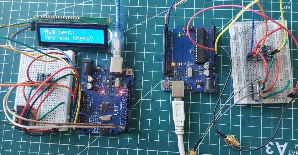
Testing the System
Now, since the hardware setup is complete and the code has been uploaded to both Arduino boards, the entire system can be tested.
Power both the controller and target circuits. Open the LightBlue BLE application on your smartphone and connect to the RYLR999 module.
During testing, observe the LCD displays on both sides and the relay module connected to the target unit. When a command is sent from the smartphone, the controller side LCD should indicate that the command has been received and transmitted. The target side LCD should display the received command and confirm that the task has been executed.
At the same time, observe the relay module and the connected appliances to verify that the correct device is being switched ON or OFF. After executing the command, the target sends a confirmation message back to the controller node.
The video below shows the complete testing process:
❕Note
Make sure that the supply wire (Vcc) of the LoRa module is disconnected from 5V before writing the code into Arduino because the pins Tx and Rx which are used to flash the code into Arduino are the same pins which are used to communicate with the module, hence it creates problem while writing code to Arduino. After flashing the code reconnect the Vcc of Module to 5V and reset the Arduino.
Troubleshooting Guide
If the system does not work as expected, check the following points:
Issue 1: LoRa Modules Not Communicating
Ensure that the controller and target modules have different addresses and that the correct address is used when sending data. Also verify that both modules are powered properly and connected to the correct RX and TX pins.
Issue 2: No Command Received on Target
If the target LCD shows “No Command Received”, check whether the LoRa modules are correctly initialized. Also confirm that both modules are configured with the correct baud rate and communication settings.
Issue 3: BLE Device Not Visible in LightBlue App
Make sure the controller unit is powered and the BLE functionality of the RYLR999 module is active. If the device does not appear in the list, try restarting the module or refreshing the scan in the LightBlue application.
Issue 4: Relay Not Switching the Appliance
Verify that the relay module receives power from the Arduino and connected to the correct Arduino pins. Also check the external wiring of the relay connected to the appliance.
Issue 5: LCD Not Displaying Any Text
Check the I2C connections (SDA and SCL) between the LCD and Arduino. Also confirm that the LCD address defined in the code matches the actual I2C address of the display.
Issue 6: The mobile application writes value but it is not received in Controller setup.
Make sure the mobile application is connected to the correct BLE as when both the controller and target are powered up, the mobile shows the BLE modules of both the controller and target when both are in range. Hence first turn ON the contoller circuit search for REYAX module and connect with it (also write the MAC id of module for future reference) then turn ON the target setup. Later from the MAC addresses we can find we are connected with the right module or not.
FAQ’S
Why is LoRa used instead of Wi-Fi or Bluetooth?
LoRa is designed for long-range and low-power communication, making it suitable for applications where devices are located far apart or where internet connectivity is not available.
Can more appliances be added to this system?
Yes. Additional appliances can be controlled by connecting more relay channels and defining additional commands in the code.
Can the smartphone control the target directly?
No. The smartphone communicates with the controller node through BLE, and the controller forwards the commands to the receiver using LoRa communication.
What frequency does the RYLR999 LoRa module operate on?
The module typically operates in the frequency range of 820-960 MHz.
