

The ESP32 is one of the most widely used microcontrollers available today. It is an upgraded version of the ESP8266, offering dual-core processor, Wi-Fi and Bluetooth capabilities and low power consumption. These features make it a perfect choice for a wide range of IoT applications.
In this guide, we’ll help you get started with the ESP32 — from choosing the right development board to installing the necessary tools and writing your first program.
Introducing the ESP32
The ESP32 is a series of low-cost microcontrollers developed by Espressif Systems, a Chinese company. Unlike traditional microcontrollers, the ESP32 is not just a chip—it’s a complete development platform. It integrates not only the processor and memory but also Wi-Fi, Bluetooth, and various hardware interfaces in a single chip. The default chip used in most ESP32 boards is the ESP-WROOM-32 module, which encapsulates the ESP32 SoC, flash memory, antenna, and oscillator in one ready-to-use package.
ESP32 Features
Dual-core Processor
The ESP32 comes with Xtensa® 32-bit LX6 microprocessor having dual-core architecture (core0 and core1). This dual-core architecture allows the ESP32 to handle multiple tasks in parallel, improving performance and responsiveness. It runs at up to 240 MHz and it can perform up to 600 DMIPS (Dhrystone millions of instructions per second).

Integrated Wi-Fi (2.4 GHz)
ESP32 comes with a built-in 2.4 GHz Wi-Fi transceiver that supports the IEEE 802.11 b/g/n standard—which means it can deliver Wi-Fi performance up to 150 Mbps. Not only does the chip support Station (STA) mode to connect to existing networks, but it can also operate as a SoftAP (Access Point)—letting other devices connect directly to it
Bluetooth 4.2 (Classic + BLE)
ESP32 supports both Bluetooth Classic and Bluetooth Low Energy (BLE). This dual-mode capability enables it to communicate with older Bluetooth devices using Bluetooth Classic as well as modern IoT devices using BLE.
Rich Peripheral Support
It offers a variety of peripherals. It includes multiple GPIOs, ADC (12-bit), DAC (8-bit), PWM channels, SPI, I2C, UART, CAN interface and much more. It also supports capacitive touch sensing, hall effect sensing, and SD card interface.
Ultra-Low Power Consumption
With its intelligent power management architecture, the ESP32 provides ultra-low power consumption, making it an ideal choice for battery-operated devices, wearables, and IoT applications. It supports multiple power modes—including active, modem-sleep, light-sleep, deep-sleep, and hibernation which allow the microcontroller to optimize its power usage.
Compatible with Multiple Development Platforms
The ESP32 supports a wide range of development platforms. You can program it using the Arduino IDE, Espressif IoT Development Framework (ESP-IDF), PlatformIO, Visual Studio Code, and Espruino. This wide selection of tools makes the ESP32 incredibly flexible.
Different Types of ESP32 Development Boards
ESP32 development boards are built around the ESP32 system-on-chip (SoC), which is designed and manufactured by Espressif Systems. While Espressif offers several development boards, many third-party manufacturers design their own custom development boards using Espressif’s modules. These boards typically include additional components like USB-to-serial converters, voltage regulators, pin headers, and sometimes onboard peripherals like OLED displays, cameras, or microSD card slots. These boards not only make prototyping and development easier but are also budget-friendly, making them an excellent choice for students and hobbyists.
Because of this flexible ecosystem, you’ll find a wide variety of ESP32 boards in the market. Some boards are beginner-friendly and ideal for learning or experimenting while others are designed for more advanced and specialized applications. Here are some of the most commonly used ESP32 development boards:
Beginner-Friendly Boards
ESP32-DevKitC
This is Espressif’s official development board. It supports multiple ESP32 module variants such as ESP32-WROOM-32, ESP32-WROVER, and ESP32-SOLO-1. This board is ideal for general-purpose projects and is a great starting point for developers looking to work within the ESP-IDF environment.
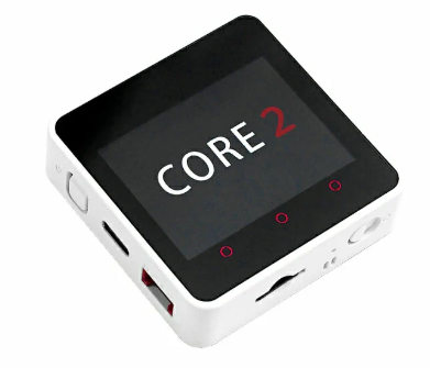
M5Stack Core2
The M5Stack Core2 is an all-in-one ESP32 development kit ideal for rapid prototyping and smart IoT interfaces. It offers a built-in RTC module, microSD, and various built-in sensors in a sleek enclosed modular design. It allows building interactive apps without needing extra displays or buttons. It can also be expanded vertically by stacking additional sensor or interface modules.
ESP32-CAM
The ESP32-CAM features a built-in OV2640 2MP camera module and a microSD card slot for image storage. It’s ideal for IoT projects that require a camera such as video streaming, motion detection, face recognition, and surveillance systems.

Advanced Boards
ESP32-S3-DevKitC
Built on the ESP32-S3, this board provides Wi-Fi and BLE 5.0 with long-range & mesh support. Its dual-core processing, built-in AI instructions, and USB OTG functionality make it ideal for advanced AIoT applications such as voice-activated devices or a camera-based system.
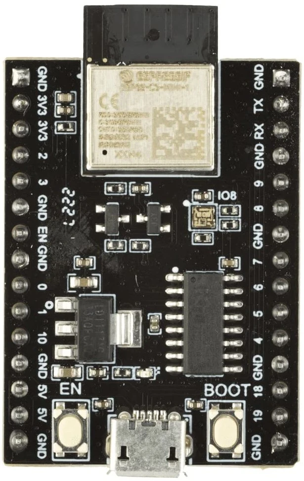
ESP32-C3-DevKitM-1
This is a compact RISC-V board that offers low power, RISC-V architecture, and security features in a compact form. It is an excellent choice for developers who need a low-cost and RISC-V-based development board. It is especially suited for battery-powered IoT applications.
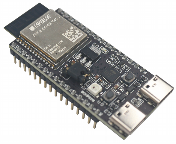
ESP32-C6-DevKitC-1
ESP32-C6-DevKitC-1 is an advanced development board aimed at next-generation IoT. With built-in Wi-Fi 6, Bluetooth 5/ BLE, and Thread/Zigbee support, it’s perfect for smart home applications and low-power wireless networks. Its RISC-V core and multiple wireless protocols make it a versatile tool for developers working on energy-efficient solutions. It also includes security features such as secure boot, flash encryption, cryptographic accelerators.
ESP32-H2-DevKitM-1
This is Espressif’s official development board based on the ESP32-H2 SoC, designed specifically for low-power, short-range wireless communication — particularly IEEE 802.15.4 (for Thread and Zigbee) and Bluetooth Low Energy (BLE) 5.2. This makes it perfect for Matter applications, smart home automation systems, and energy-efficient mesh networking applications.

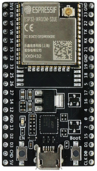
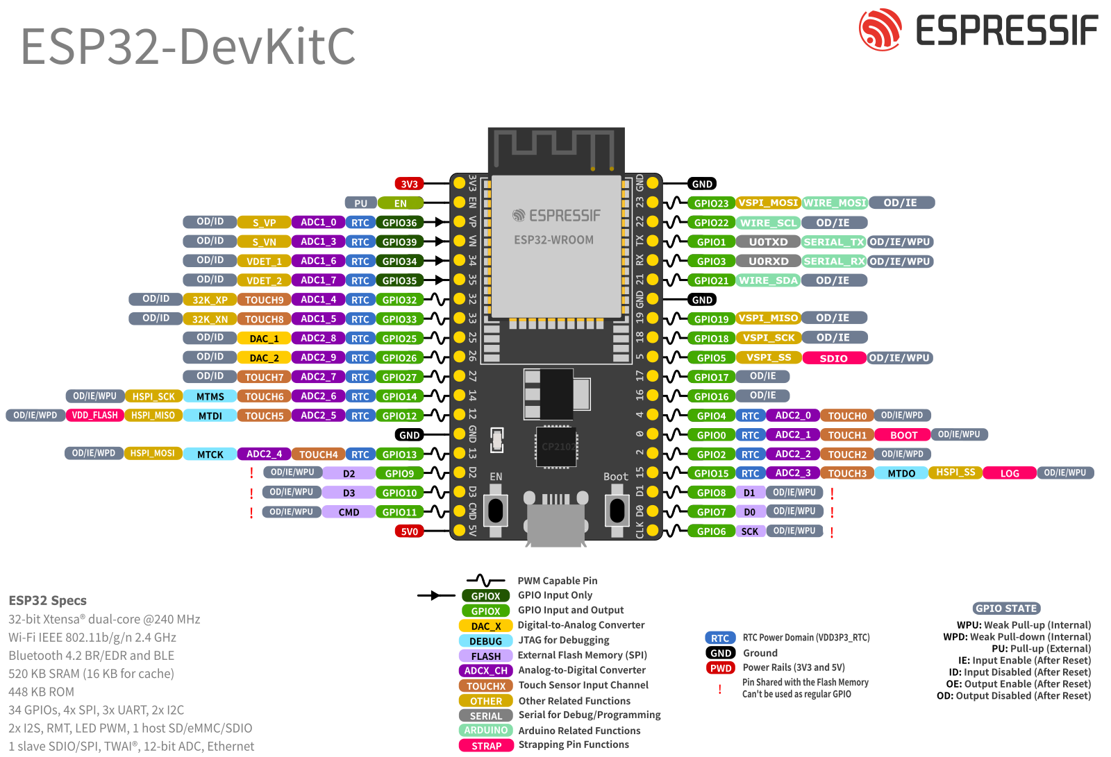
ESP32 DevKitC V4 Board Hardware Overview
The ESP32-DevKitC V4 is one of the most widely used development boards. This board will be our primary focus.

ESP32-WROOM-32E Module At the core of the ESP32-DevKitC is the ESP-WROOM-32 SoC module. This module integrates a dual-core Tensilica Xtensa 32-bit LX6 processor along with built-in Wi-Fi (802.11 b/g/n) and Bluetooth (Classic and BLE). It operates between 80 MHz and 240 MHz, with dynamic frequency scaling, clock gating, and CPU power-off modes to optimize energy efficiency. It has 4 MB of SPI flash memory and 520 KB of internal SRAM.
5V Power-On LED A 5V LED indicates that an external 5V power supply is connected to the board. Its function is to confirm that the board is being powered correctly.
I/O Connectors (J2 & J3 headers) The I/O connectors are the two long header rows on either side of the ESP32-WROOM-32E module. They are designed to break out most of the ESP32’s GPIOs along with access to the chip’s internal peripherals—such as UART, SPI, I²C, ADC, DAC, PWM, and touch sensing. This means through these pins you can easily interface board with sensors, modules, and shields using jumper wires.
BOOT Button The BOOT button forces the ESP32 into firmware download mode by pulling GPIO0 low during reset. Its main purpose is to let you upload new programs to the board. It’s usually not required, since the USB-UART chip handles this automatically, but it’s used as a backup when auto-programming fails.
EN Button (Reset) This button resets the ESP32. In the flash-mode sequence it’s used alongside BOOT to enter the serial downloader.
USB-to-UART Bridge DevKitC V4 has a single USB-UART bridge chip (CP2102N) which is connected to the Micro-USB port. Through this you can open the serial console to monitor debug messages or send commands. It also supports auto-programming by controlling the reset and boot buttons (EN and BOOT) using its DTR/RTS lines. Thus the board enters download mode without pressing buttons manually each time you upload code.
USB-to-UART Port (Micro-USB The USB-to-UART port (Micro-USB) is used to power the board, upload programs, and communicate with the ESP32 through serial monitor.
ESP-WROOM-32E Memory Overview
The ESP32-WROOM-32E has different types of memory:
-
ROM (448 KB) – Read-Only Memory, factory programmed.
-
SRAM (520 KB) – General-purpose working memory for your program.
-
RTC SRAM (16 KB) – Special low-power memory that stays on when the chip is in deep sleep, used by the ultra-low-power co-processor.
What’s inside the ROM?
- Bootloader: The very first piece of the code that runs after reset, which decides whether to boot from Flash or enter UART download mode i.e., write new program in flash memory.
- Wi-Fi & Bluetooth firmware stacks (partly): Some low-level routines are burned into ROM to save space in Flash.
- Standard library functions: Functions like
memcpy,memcmp, are built-in, so you don’t need to compile them in every project.
We cannot change ROM contents. It’s permanent and the same for all ESP32 chips.
The external flash is used to save program when we program the ESP 32 kit.
How program execution works?
-
Your main program is stored in external Flash (not in ROM).
-
When the ESP32 resets:
-
The ROM bootloader runs first.
-
It loads your program from Flash into RAM (SRAM).
-
Then the CPU executes the program from RAM.
-
How to Power the ESP32 Board?
The ESP32 DevKitC can be powered in multiple ways. The most common method is through the micro-USB port, which provides 5V input. As its operating voltage is 3.0V to 3.6V, it includes an onboard 3.3V voltage regulator that steps down this voltage (5V) to 3.3V. The regulator provides a maximum output current of around 600mA, which is sufficient for most basic applications. Alternatively, the board can be powered directly via the VIN pin by supplying a regulated 5V source.
When you power the board through the USB port, 5V is available on 5V pin, which can also be used to power peripherals that operate at 5V. However, you must be cautious not to draw too much current from this pin, especially if the board is powered only through USB.
This 5V pin can be used to feed the power to the board when it is not powered with USB, which in turn passed through LDO which powers ESP 32 with its 3v3 volt output.
Power Requirement
- Operating Voltage: 3.0V to 3.6V
- On-board 3.3V 600mA regulator
- Input Voltage (via USB): 5V from the micro-USB port
- Input Voltage (via VIN pin): 5V to 6V, the on-board regulator can take 12 V input but at higher voltages (7 to 12 V) the regulator becomes very hot hence it is recommended to limit VIN to ~5–6V.
❕Note
There are three ways to provide power to the board which are mutually exclusive i.e., only one can be used at a time.
- Micro USB port, default power supply
- 5V and GND header pins
- 3V3 and GND header pins
The power provided via 3V3 header pin or VIN pin must be regulated.
The tables below provide header pins by their name and function, making it easy to identify what each pin can do—whether it’s a GPIO, or connected to one of the ESP32’s built-in peripherals like UART, I2C, SPI, ADC, DAC, etc.
J2
| Pin Number | Pin Name | Pin Type | Function |
|---|---|---|---|
| 1 | 3V3 | Power supply | 3.3 V power supply |
| 2 | EN | Input | CHIP_PU, Reset |
| 3 | VP | Input | GPIO36, ADC1_CH0, S_VP |
| 4 | VN | Input | GPIO39, ADC1_CH3, S_VN |
| 5 | IO34 | Input | GPIO34, ADC1_CH6, VDET_1 |
| 6 | IO35 | Input | GPIO35, ADC1_CH7, VDET_2 |
| 7 | IO32 | Input/Output | GPIO32, ADC1_CH4, TOUCH_CH9, XTAL_32K_P |
| 8 | IO33 | Input/Output | GPIO33, ADC1_CH5, TOUCH_CH8, XTAL_32K_N |
| 9 | IO25 | Input/Output | GPIO25, ADC2_CH8, DAC_1 |
| 10 | IO26 | Input/Output | GPIO26, ADC2_CH9, DAC_2 |
| 11 | IO27 | Input/Output | GPIO27, ADC2_CH7, TOUCH_CH7 |
| 12 | IO14 | Input/Output | GPIO14, ADC2_CH6, TOUCH_CH6, MTMS |
| 13 | IO12 | Input/Output | GPIO12, ADC2_CH5, TOUCH_CH5, MTDI |
| 14 | GND | Ground | Ground |
| 15 | IO13 | Input/Output | GPIO13, ADC2_CH4, TOUCH_CH4, MTCK |
| 16 | D2 | Input/Output | GPIO9, D2 |
| 17 | D3 | Input/Output | GPIO10, D3 |
| 18 | CMD | Input/Output | GPIO11, CMD |
| 19 | 5V | Power supply | 5 V power supply |
J3
| Pin Number | Pin Name | Pin Type | Function |
|---|---|---|---|
| 1 | GND | Ground | Ground |
| 2 | IO23 | Input/Output | GPIO23 |
| 3 | IO22 | Input/Output | GPIO22 |
| 4 | TX | Input/Output | GPIO1, U0TXD |
| 5 | RX | Input/Output | GPIO3, U0RXD |
| 6 | IO21 | Input/Output | GPIO21 |
| 7 | GND | Ground | Ground |
| 8 | IO19 | Input/Output | GPIO19 |
| 9 | IO18 | Input/Output | GPIO18 |
| 10 | IO5 | Input/Output | GPIO5 |
| 11 | IO17 | Input/Output | GPIO17 |
| 12 | IO16 | Input/Output | GPIO16 |
| 13 | IO4 | Input/Output | GPIO4, ADC2_CH0, TOUCH_CH0 |
| 14 | IO0 | Input/Output | GPIO0, ADC2_CH1, TOUCH_CH1, Boot |
| 15 | IO2 | Input/Output | GPIO2, ADC2_CH2, TOUCH_CH2 |
| 16 | IO15 | Input/Output | GPIO15, ADC2_CH3, TOUCH_CH3, MTDO |
| 17 | D1 | Input/Output | GPIO8, D1 |
| 18 | D0 | Input/Output | GPIO7, D0 |
| 19 | CLK | Input/Output | GPIO6, CLK |
Ground Pins There are 3 ground (GND) pins on the board. You can use any of them to complete circuits when connecting sensors, modules, LEDs, or other devices. Having multiple GND pins ensures that you can always find a convenient location to ground your components on either side of the board, especially when working on a breadboard setup.
GPIO Pins The ESP32-DevKitC-32E board provides a total of 26 usable GPIO (General Purpose Input/Output) pins that are broken out to the side headers (J2 and J3). of the board for easy access. These GPIO pins allow you to interface with a wide variety of external components such as LEDs, sensors, buttons, displays, and more.
One of the powerful features of the ESP32 is its flexible pin functions—many GPIOs can serve multiple roles like PWM, ADC, DAC, I2C, SPI, UART, and touch sensing.
Analog Input (ADC) Pins Several pins on the DevKitC-32E support analog input, meaning they can read varying voltage levels, which is useful for sensors like temperature sensors, potentiometers, and light sensors. Analog input is handled by the ADC (Analog-to-Digital Converter).
Analog Output (DAC) Pins The board includes two DAC (Digital-to-Analog Converter) channels which allow it to generate analog voltage outputs. These can be programmed to output variable voltage levels. This is useful for applications like audio output, variable LED dimming without PWM, or analog signal generation.
Touch Sensor Pins The ESP32 includes capacitive touch sensing capability on 9 pins, allowing you to build touch buttons without physical switches. These pins can detect changes in capacitance when touched by a human finger, making them perfect for modern touch interfaces in your DIY projects. Some touch pins overlap with ADC2 and strapping/boot pins (e.g., GPIO2, GPIO12, GPIO15). Be cautious when using those.
SPI Communication Pins The ESP32 supports SPI (Serial Peripheral Interface) for high-speed data exchange with devices like SD cards, OLED displays, and shift registers. We can use any pin for the SPI if it is possible using the GPIO matrix but on the ESP32-DevKitC-32E V4, the default VSPI(SPI3) bus(default SPI pins) uses GPIO19 (MISO), GPIO23 (MOSI), GPIO18 (SCK), and GPIO5 (CS).
I2C Communication Pins For connecting sensors and modules with fewer wires, the ESP32 supports I2C (Inter-Integrated Circuit) communication. We can assign SDA and SCL to almost any GPIO using the GPIO matrix, but the default I2C pins are pin 21 (SDA) and pin 22 (SCL). These two pins are typically used with I2C displays, temperature sensors, and other modules that support address-based communication over a shared two-wire bus. We will need pull-up resistors (4.7 kΩ typical) on SDA and SCL for reliable operation, unless it is provided by the module itself we are interfacing these I2C pins.
UART Communication Pins The board supports UART communication for serial devices such as GPS modules, GSM modules, or simply for logging and debugging. The USB port on the board connects to pin 1 (TX) and pin 2 (RX), which are used by UART0, the default programming and serial monitor interface. For additional UART peripherals, software serial or hardware UART1/UART2 can be assigned to other available digital pins.
The ESP32-DevKitC-32E V4 supports UART communication for serial devices like GPS or GSM modules, or simply for logging and debugging. The ESP32 has 3 hardware UART controllers (UART0, UART1, UART2) and all can be remapped to almost any GPIO via the GPIO matrix. By default ,the USB port connects to UART0 (GPIO1 TX, GPIO3 RX) for programming and debugging. Additional UART peripherals can use UART2 (GPIO16/17). UART 1 is not available on Development kit headers.
PWM (Pulse Width Modulation) We can generate PWM on almost any usable GPIO except input-only pins and flash-dedicated ones. It uses a flexible LEDC (LED Controller) peripheral that can output PWM signals. The PWM pins can be used to dim LEDs, control motor drivers, generate tones, or create variable duty-cycle waveforms. There 21 pins on the Development board which can produce PWM. But the ESP32 supports up to 16 independent PWM channels, each configurable in frequency (1 Hz–40 MHz) and resolution (1–20 bits). If we have to produce PWM on 21 pins at the same time then, we have to duplicate a channel to multiple pins which leads to same frequency & duty cycle on two pins as we could have only 16 unique outputs which can exits at once.
ESP32 Development Platforms
The ESP32 microcontroller can be programmed using a variety of platforms. The most commonly used development environment is the Arduino IDE. It is ideal for hobbyists and those transitioning from Arduino boards like the UNO or Nano.
Another popular option is the Espressif IoT Development Framework (ESP-IDF) — the official development platform provided by Espressif Systems. ESP-IDF is a more advanced environment suitable for experienced developers who need full control over the hardware. Developers using ESP-IDF can take advantage of more advanced features like multithreading, secure boot, OTA updates, and low-power modes. The build system relies on CMake and Python-based tools, and development is typically done using Visual Studio Code or the Eclipse IDE.
Other supported platforms include PlatformIO, an open-source ecosystem that supports multiple boards and frameworks, and integrates easily with VS Code. It provides an excellent balance between ease of use and control.
Additionally, languages like MicroPython and JavaScript (via Espruino) are also supported, allowing developers from various backgrounds to work with ESP32 using familiar syntax. These options make the ESP32 one of the most flexible and accessible microcontrollers available in the market.
Installing the ESP32 Arduino Core
To program ESP32 boards using Arduino IDE, you first need to install the ESP32 board support package. Follow these steps to set it up using the Arduino IDE 2.x.
Go to the official Arduino website: https://www.arduino.cc/en/software
and download the latest Arduino IDE 2.x. Then install the IDE.
Step 1 Launch Arduino IDE then click on the File > Preferences.
Step 2 In the Preferences window, find the field “Additional Board URLs”
- If the box is empty then paste the following link:
https://raw.githubusercontent.com/espressif/arduino-esp32/gh-pages/package_esp32_index.json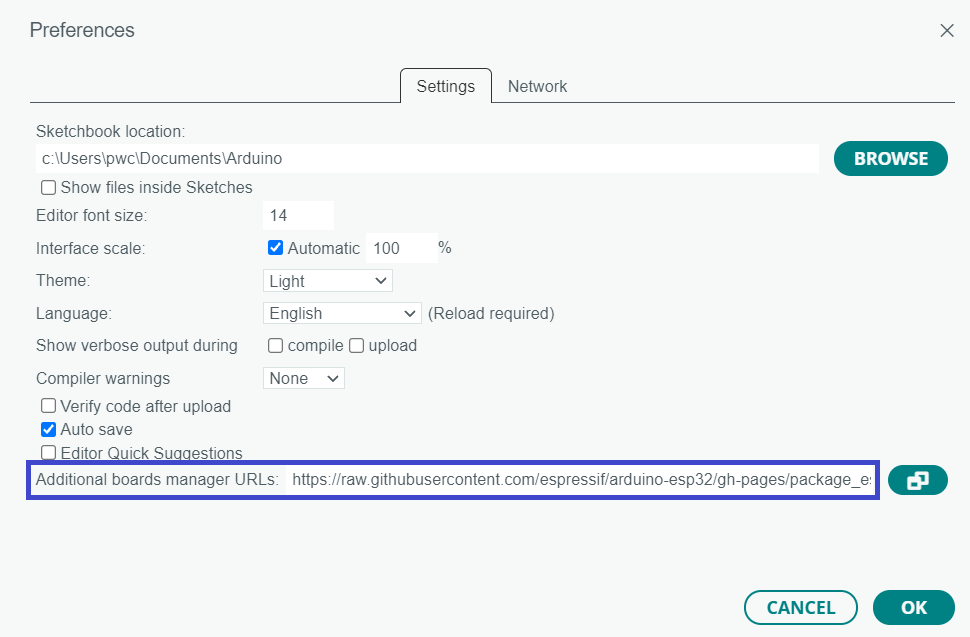
Then, click OK to save your changes.
- If there is already another URL (like ESP8266) in the board manager field → click the copy/link icon next to the box.
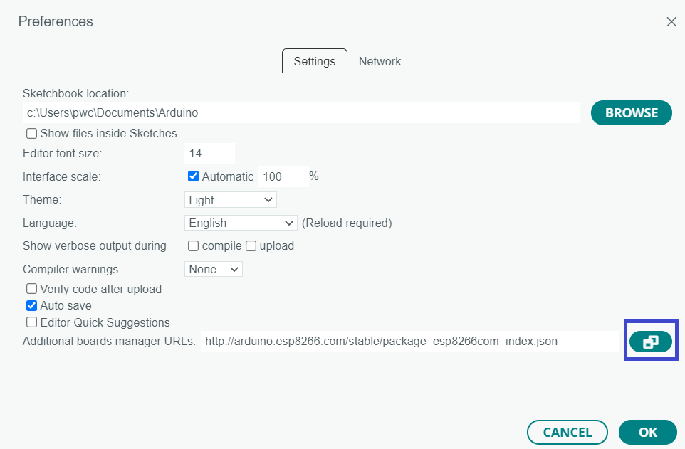
A pop-up window will open. Paste the above URL on a new line and then click OK.

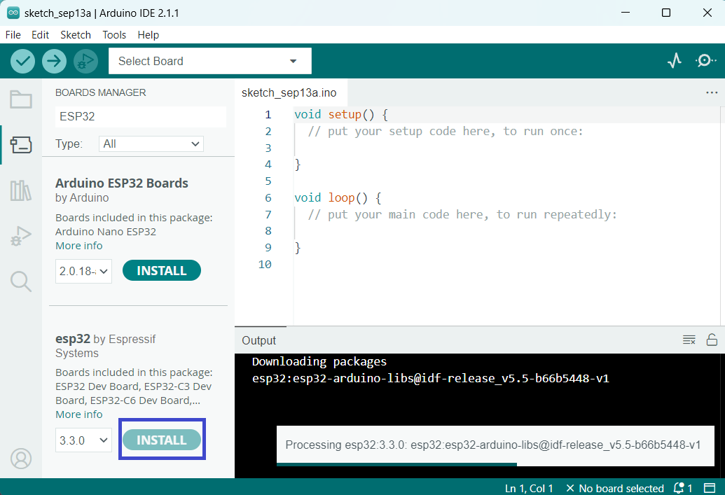
Step 3 Click on the Boards icon (chip symbol) in the left sidebar, or go to Tools > Board > Board Manager.
In the Boards Manager window, type “ESP32” in the search bar. Look for the package named “esp32 by Espressif Systems”.
Click Install next to it.
Step 4 Plug your ESP32 board (e.g., DevKitC-32E) into your computer via USB.
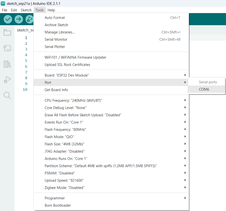
Go to Tools > Port and select the port that shows your ESP32 (e.g., COM3 on Windows or /dev/ttyUSB0 on Linux).
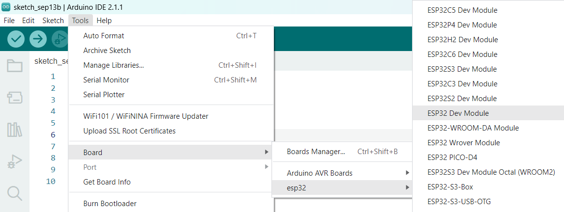
Go to Tools > Board > esp32.
Scroll and select the exact model of your board.
Finally, connect the ESP32 board to your computer. In Arduino IDE, go to Tools → Port and select the COM port for your board.
If no port appears, it probably means the driver is missing. Most ESP32 boards use the CP210x USB-to-UART Bridge (or sometimes CH340), so install the windows driver.
Your ESP32 board is now ready to be programmed using Arduino IDE!
ESP32 Example Sketches
The ESP32 Arduino core comes with several example sketches. To access them in the Arduino IDE:
- Go to the File > Examples > ESP32 menu.
- You’ll see a list of example categories.
- Choose any sketch and it will open in your IDE.
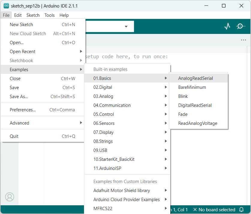
Basic Example Code: Blink
To verify that ESP32 is properly configured, we’ll upload the basic – Blink sketch. It helps us confirm that the board, development environment, and upload process are all working correctly.
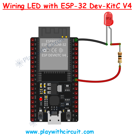
In this example, we configure GPIO 5 of the ESP32 as an output pin. The code repeatedly turns the LED ON for 500 ms and then OFF for 500 ms, creating a continuous blinking effect.
/*
 Interfacing LED with ESP32 DevKitC V4 having ESP-WROOM-32E Module as SOC, by www.playwithcircuit.com
*/
// The GPIO 5 of the SOC module is connected to the 10 pin of J3 connector on the Development kit
int ledPin = 5;

void setup() {
  pinMode(ledPin, OUTPUT); // set the pin as output
}

void loop() {
  digitalWrite(ledPin, HIGH); // turn pin high
  delay(500);
  digitalWrite(ledPin, LOW); // turn pin low
  delay(500);
}
Once the code is successfully uploaded to your ESP32, the LED connected to GPIO 5 will begin to blink with a half-second interval.
FAQ’S
What is the main difference between ESP32 and ESP8266?
- Processing power: ESP32 is dual-core with higher clock speed, while ESP8266 is single-core.
- Connectivity: ESP32 supports both Wi-Fi and Bluetooth (classic + BLE), while ESP8266 only supports Wi-Fi.
- GPIO & peripherals: ESP32 has more GPIOs and supports ADC, DAC, capacitive touch, CAN, etc. while ESP8266 has fewer pins and limited ADC.
- Power modes: ESP32 offers better low-power options (deep sleep, ULP coprocessor).
What can you do with ESP32?
-
With ESP32, you can:
-
Create wireless sensor networks for monitoring temperature, humidity, or motion.
-
Build robots, drones, and remote-controlled vehicles using Wi-Fi or Bluetooth.
-
Stream audio or voice commands with its built-in DAC and I²S support.
-
Run portable, battery-powered gadgets by using its deep sleep and low-power features.
- Create smart home devices
-
What are the advantages of ESP32 over Arduino?
The ESP32 offers several advantages compared to Arduino boards (like UNO or Nano):
-
Built-in Wi-Fi and Bluetooth: No need for external modules (unlike Arduino).
-
Higher performance: Dual-core processor up to 240 MHz vs. Arduino UNO’s single-core 16 MHz.
-
Low-power modes → Deep sleep and ULP coprocessor for battery-powered projects.
- More memory: 520 KB SRAM + external Flash vs. only 2 KB SRAM on Arduino Uno.
Why is ESP32 not showing on com port?
If the ESP32 does not show up on the COM port, it usually means your computer is not detecting the USB-to-serial chip on the board. This can happen due to missing drivers (CP2102/CH340), using a charge-only USB cable, or a loose connection. You can fix this by installing the correct driver, using a proper data cable, and then rechecking the port in Arduino IDE.
