
Water tank overflow is a common issue in many households that can lead to significant water wastage. This problem can be easily fixed by using a water level sensor. The sensor can monitor the water level in the tank and stop the overflow.
In this tutorial, we’ll learn how water level sensor work and how to interface it with an Arduino. We will also build a water level indicator that triggers an LED and a buzzer when the water reaches a certain level.
How does a Water Level Sensor Work?
The water level sensor uses a simple mechanism to detect the water level in an overhead tank or any other water container. It works by measuring the change in resistance of conductive traces as it is immersed in water.
The resistance changes based on how much of the sensor is immersed in water.
- When the sensor is immersed in more water, the conductivity improves, and the resistance decreases.
- When the sensor is immersed in less water, the conductivity decreases and resistance increases.
This varying resistance generates an output voltage that is proportional to the water level. By measuring this voltage, you can determine the water level.
Specifications
- Operating voltage: 3 to 5V, < 20mA
- Humidity: 10%-90% non-condensing
- Operating Temperature: 10℃-30℃
- Sensor Type: Analog
- Output Voltage Range: 0 to 3.85V
- Detection Area: 40mm (height) x 16mm (width)
Hardware Overview
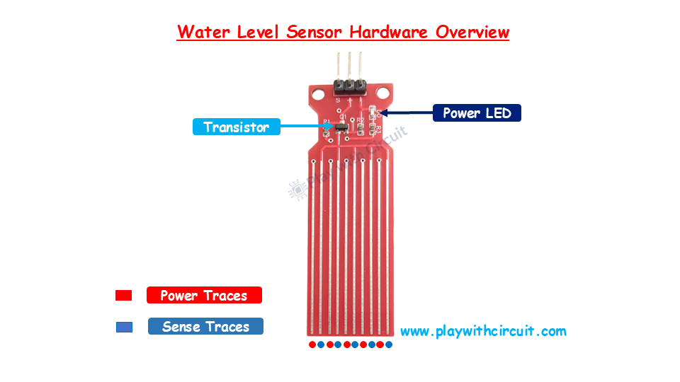
The sensor has a series of ten exposed copper traces. Five are Power Traces that carry the voltage necessary for the sensor to operate and five are Sense Traces that detect the presence of water. These traces are intertwined so that each sense trace is positioned between two power traces.
When the sensor is dipped in the water, it bridges the gap between the sense traces and the power traces, allowing the sensor to detect the water level effectively.
The module has a power LED which indicates that the sensor is powered on. It also has a transistor and a bunch of resistors.
Water Level Sensor Pinout
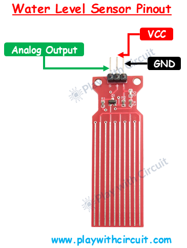
VCC This is the power supply pin of the sensor. It should be connected to the 5V pin on the Arduino.
GND This is the ground pin of the sensor.
OUT This is the analog output pin of the sensor. It provides output signals varying between 0V and Vcc based on the water level.
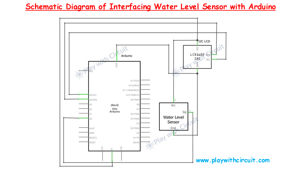
Schematic Diagram
The schematic diagram of the water level sensor is given below:
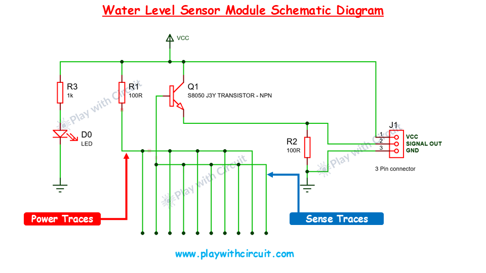
In the schematic, the emitter of the NPN transistor Q1 is connected to the ground with R2(100Ω) resistor and the collector is connected to the supply voltage Vcc. In the sensor module, 5 power traces are connected with the Vcc in series through R1 (100Ω) resistor and 5 sense traces are connected to the base of the transistor. Here the current-limiting resistors (R1, R2, R3) are used to protect both the transistor and LED.
When these traces comes in the contact of water, a signal is sent to the base of the transistor, allowing current to flow from the collector to the emitter, switching the transistor on.
The power LED lights up when 5V is connected to VCC and the Signal Out pin provides the Analog output which changes as water level changes.
Wiring a Water Level Sensor to Arduino
Now let’s connect the water level sensor to Arduino UNO. The circuit diagram is shown as follows:
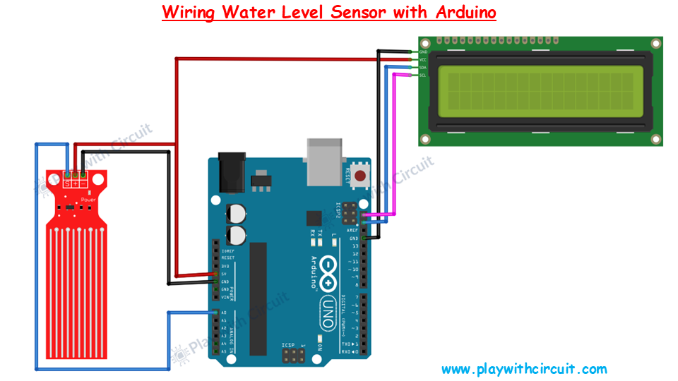
Connect the Vcc and Gnd of the water level sensor to the Vcc and Gnd pin of the Arduino UNO. The Sensor Out pin of the water level sensor is connected to the analog input pin of the Arduino.
Now connect SCK and SDA pins of LCD is to I2C pin of the Arduino. Then connect Vcc and Ground to the Vcc and Ground pins of Arduino and sensor.
Here is the schematics diagram:
Arduino Code for Interfacing Water Level Sensor Module with Arduino
Upload the following sketch to your Arduino.
/*
Interfacing Water Level Sensor with Arduino UNO using Analog Output pin of Module
by www.playwithcircuit.com
Using this code we will know the Analog Value when water level is very low and when it is very high.
*/

#include <LiquidCrystal_I2C.h>  // Library to Run I2C LCD

// define the size of filter array
#define FILTER_SIZE 20

// Set the LCD address to 0x27 for a 16 chars and 2 line display
LiquidCrystal_I2C lcd(0x27, 16, 2);

// Define the analog pin for the soil moisture sensor
const int WaterSensorPin = A0;

// Analog Value filter
int Filter(int sensorValue);

void setup() {
  // initialize the lcd
  lcd.init();
  // Turn on the Backlight
  lcd.backlight();
  // Clear the display buffer
  lcd.clear();
  // Print a message to the LCD
  lcd.setCursor(0, 0);
  lcd.print("Analog Value:");
}

void loop() {

  // Variable to store sensor values
  int sensorValue;
  // Variable to store filtered values
  int filteredValue;

  // Read the value from the soil moisture sensor
  sensorValue = analogRead(WaterSensorPin);
  filteredValue = Filter(sensorValue);

  // Display the filtered Analog Value on the LCD
  lcd.setCursor(0, 1);
  lcd.print(filteredValue);
  // Clear Previous Data
  lcd.print("   ");

  // Wait for 50ms before the next loop
  delay(50);
}

// Averaging filter to filter Analog Values
int Filter(int sensorValue) {
  static int analogArray[FILTER_SIZE] = { 0 };
  int filteredValue = 0;
  int i;

  // Shift the Elemnent removing the oldest value stored at index 0
  for (i = 0; i < (FILTER_SIZE - 1); i++) {
    analogArray[i] = analogArray[i + 1];
  }

  // Put the current value in the last element of Array i.e at index FILTER_SIZE-1
  analogArray[FILTER_SIZE-1] = sensorValue;

  for (i = 0; i < FILTER_SIZE; i++) {
    filteredValue += analogArray[i];
  }

  // Return Filtered Analog Value
  return (filteredValue / FILTER_SIZE);
}
Code Explanation
First we include LiquidCrystal_I2C.h library to control an I2C-enabled LCD display. This library allows communication between the Arduino and the LCD via the I2C protocol.
#include <LiquidCrystal_I2C.h> // Library to Run I2C LCDNow we define the size of the array used to filter the sensor readings.
// define the size of filter array
#define FILTER_SIZE 20
Then we create an object named lcd with the I2C address 0x27, specifying that it’s a 16×2 LCD. Then we define the Analog Pin A0 of the Arduino to which the sensor is connected.
// Set the LCD address to 0x27 for a 16 chars and 2 line display
LiquidCrystal_I2C lcd(0x27, 16, 2);

// Define the analog pin for the soil moisture sensor
const int WaterSensorPin = A0;
Following that, we declare a function named Filter. It will be used to average the raw analog readings from the sensor and reduce noise.
// Analog Value filter
int Filter(int sensorValue);
In the setup function, we initialize the LCD, turns on the backlight, clears any previous data, and prints “Analog Value:” on the first line of the LCD.
void setup() {
  // initialize the lcd
  lcd.init();
  // Turn on the Backlight
  lcd.backlight();
  // Clear the display buffer
  lcd.clear();
  // Print a message to the LCD
  lcd.setCursor(0, 0);
  lcd.print("Analog Value:");
}
In the loop function, first we initialize the variables to store sensor values and filtered values. The we read the analog value from the sensor using analogRead.
The raw value is passed through the Filter() function to smooth it out. The filtered value is then printed on the second row of the LCD.
Here a delay of 50 milliseconds is added to prevent the LCD from updating too quickly.
void loop() {

  // Variable to store sensor values
  int sensorValue;
  // Variable to store filtered Values
  int filteredValue;

  // Read the value from the soil moisture sensor
  sensorValue = analogRead(WaterSensorPin);
  filteredValue = Filter(sensorValue);

  // Display the filtered Analog Value on the LCD
  lcd.setCursor(0, 1);
  lcd.print(filteredValue);
  // Clear Previous Data
  lcd.print("   ");

  // Wait for 50ms before the next loop
  delay(50);
}
The Filter() function creates an array analogArray to store the last 20 sensor readings. The oldest reading (at index 0) is discarded, and the new reading is stored at the last index (FILTER_SIZE-1).
The for loop sums up all the readings in the array. The average value is then calculated by dividing the sum by the size of the array (FILTER_SIZE), which gives the filtered sensor value.
// Averaging filter to filter Analog Values
int Filter(int sensorValue) {
  static int analogArray[FILTER_SIZE] = { 0 };
  int filteredValue = 0;
  int i;

  // Shift the Elemnent removing the oldest value stord at index 0
  for (i = 0; i < (FILTER_SIZE - 1); i++) {
    analogArray[i] = analogArray[i + 1];
  }

  // Put the current value in the last element of Array i.e, at index FILTER_SIZE-1
  analogArray[FILTER_SIZE-1] = sensorValue;

  for (i = 0; i < FILTER_SIZE; i++) {
    filteredValue += analogArray[i];
  }

  // Return Filtered Analog Value
  return (filteredValue / FILTER_SIZE);
}
How to Calibrate Water Level Sensor?
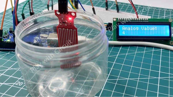
To calibrate a water level sensor, we need to determine threshold values. Here are the steps to find threshold analog values.
- First upload the above sketch in the Arduino UNO.
- Put the sensor in the transparent container.
- Fill the water in the container so the it just touches the tip of the sensor traces.
- Write down the analog value at this low threshold level.
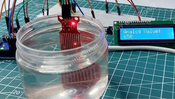
- Now fill the water so that sensor traces are completely submerged in water.
- Note down the analog values at this high threshold level.
Note that water type can affect sensitivity of the sensor. For example, distilled water is less conductive than tap water or mineral-rich water. The more impurities and minerals in the water, the better its conductivity.
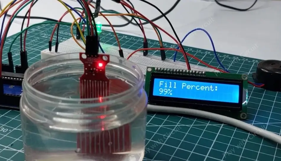
Water Level Indicator– Arduino Project
In this project, we’ll create a simple water level indicator using an Arduino, water level sensor, multi-color LED, an LCD display, and a buzzer. The system will indicate the water level inside a container and help prevent overfilling by triggering an alarm when the container is full.
How It Works:
The water level sensor detects the level of water in the container and sends this data to the Arduino. The Arduino then controls the RGB LED to display different colors for different water levels. There are three cases:
- When the water level is less than 10% then RGB LED turns red.
- When the water level is greater than or equal to 10% and less than 99% then RGB LED turns blue light.
- When the water level is greater than or equal to 99% then RGB LED emits green light. At this point the buzzer will sound indicating that the container is full and you should stop filling it.
Here we are also using an LCD to display the water level as a percentage. This percentage is calculated based on the sensor readings, where 0% represents an empty container, and 100% indicates that the container is full.
As the water level changes, the LCD will dynamically update to reflect the current percentage, providing a clear and real-time indication of the water level in the container.
Hardware and Software Requirements
Hardware Requirement
| Component Name | Quantity | Remarks | Where to Buy |
|---|---|---|---|
| Arduino UNO R3 | 1 | Revision R3 | Amazon.com / Amazon.in / Banggood |
| Water Level Sensor | 1 | Resistive type | Amazon.com / Amazon.in |
| LCD 16x2 | 1 | I2C support | Amazon.com / Amazon.in / Banggood |
| Jumper Wires | 10 | For Arduino and Sensor connections | Amazon.com / Amazon.in / Banggood |
| Breadboard | 1 | Full size | Amazon.com / Amazon.in / Banggood |
| Buzzer | 1 | 5V | Amazon.com / Amazon.in / Banggood |
| USB Cable Type A to B | 1 | for programming Arduino UNO | Amazon.com / Amazon.in |
| Resistance | 1 | 220K, Current limiting Resistance | Amazon.com / Amazon.in / Banggood |
| Multicolor LED | 1 | Common Cathode | Amazon.com / Amazon.in / Banggood |
| 12V Supply Adapter | 1 | For providing power to Arduino | Amazon.com / Amazon.in |
Software Requirement
Arduino IDE, Version 2.1.1 or above installed on your PC
Wiring Diagram
Connect your circuit according to the following diagram.
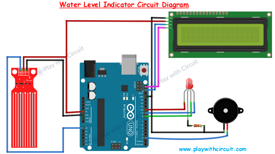
The connections of water level sensor and LCD with the Arduino are same as the previous circuit. Apart from those connections, a common cathode LED is also connected with the Arduino at pins 10, 9 and 8 for colours red, blue and green respectively. A buzzer is connected at pin 2.
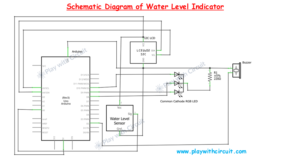
Here is the schematic diagram of water level indicator:
Arduino Code for Water Level Indicator
/*
Water Level Indicator– Arduino Project
by www.playwithcircuit.com
*/

#include <LiquidCrystal_I2C.h>  // Library to Run I2C LCD

// define the size of filter array
#define FILTER_SIZE 20
#define LOWER_THRESHOLD 4
#define UPPER_THRESHOLD 650

#define RED_PIN 10
#define BLUE_PIN 9
#define GREEN_PIN 8
#define BUZZER_PIN 2

// Set the LCD address to 0x27 for a 16 chars and 2 line display
LiquidCrystal_I2C lcd(0x27, 16, 2);

// Define the Analog pin for the soil moisture sensor
const int WaterSensorPin = A0;

// Analog Value filter
int Filter(int sensorValue);

void setup() {
  // initialize the lcd
  lcd.init();
  // Turn on the Backlight
  lcd.backlight();
  // Clear the display buffer
  lcd.clear();
  // Make LED pins and Buzzer pin as output
  pinMode(RED_PIN, OUTPUT);
  pinMode(BLUE_PIN, OUTPUT);
  pinMode(GREEN_PIN, OUTPUT);
  pinMode(BUZZER_PIN, OUTPUT);

  // Turn Off all the pins
  digitalWrite(RED_PIN, LOW);
  digitalWrite(BLUE_PIN, LOW);
  digitalWrite(GREEN_PIN, LOW);
  digitalWrite(BUZZER_PIN, LOW);

  // Print a message to the LCD
  lcd.setCursor(0, 0);
  lcd.print("Fill Percent:");
}

void loop() {
  // Variable to store sensor values
  int sensorValue;
  // Variable to store filtered Value
  int filteredValue;
  // Variable to store fill percentage
  int fillPercent;

  // Read the value from the soil moisture sensor
  sensorValue = analogRead(WaterSensorPin);
  filteredValue = Filter(sensorValue);
  fillPercent = map(filteredValue,LOWER_THRESHOLD, UPPER_THRESHOLD, 0, 100);

  // Display the filtered Analog Value on the LCD
  lcd.setCursor(0, 1);
  lcd.print(fillPercent);
  // Clear Previous Data
  lcd.print("%  ");

  // Change the color of LED as per water level
  if (fillPercent >= 99) {
    digitalWrite(RED_PIN, LOW);
    digitalWrite(BLUE_PIN, LOW);
    digitalWrite(GREEN_PIN, HIGH);
    digitalWrite(BUZZER_PIN, HIGH);
  } else if (fillPercent >= 10 && fillPercent < 99) {
    digitalWrite(RED_PIN, LOW);
    digitalWrite(BLUE_PIN, HIGH);
    digitalWrite(GREEN_PIN, LOW);
    digitalWrite(BUZZER_PIN, LOW);
  } else if (fillPercent < 10) {
    digitalWrite(RED_PIN, HIGH);
    digitalWrite(BLUE_PIN, LOW);
    digitalWrite(GREEN_PIN, LOW);
    digitalWrite(BUZZER_PIN, LOW);
  }

  // Wait for 50ms before the next loop
  delay(50);
}

// Averaging filter to filter Analog Values
int Filter(int sensorValue) {
  static int analogArray[FILTER_SIZE] = { 0 };
  int filteredValue = 0;
  int i;

  // Shift the Element removing the oldest value stored at index 0
  for (i = 0; i < (FILTER_SIZE - 1); i++) {
    analogArray[i] = analogArray[i + 1];
  }

  // Put the current value in the last element of Array i.e. at index FILTER_SIZE-1
  analogArray[FILTER_SIZE-1] = sensorValue;

  for (i = 0; i < FILTER_SIZE; i++) {
    filteredValue += analogArray[i];
  }

  // Return Filtered Analog Value
  return (filteredValue / FILTER_SIZE);
}
Code Description
The LiquidCrystal_I2C.h library is included to control the LCD via I2C communication.
#include <LiquidCrystal_I2C.h> // Library to Run I2C LCDNow we define the size of the filter array, LOWER_THRESHOLD and UPPER_THRESHOLD.
Note that the values of these macros are the same value, which we got using previous code, so you can edit the code as per your values.
RED_PIN, BLUE_PIN, GREEN_PIN, and BUZZER_PIN define the Arduino pins connected to the RGB LED and buzzer.
// define the size of filter array
#define FILTER_SIZE 20
#define LOWER_THRESHOLD 4
#define UPPER_THRESHOLD 650

#define RED_PIN 10
#define BLUE_PIN 9
#define GREEN_PIN 8
#define BUZZER_PIN 2
Then we create an object named lcd with the I2C address 0x27, specifying that it’s a 16×2 LCD. Then we define the Analog pin A0 of the Arduino to which the sensor is connected.
// Set the LCD address to 0x27 for a 16 chars and 2 line display
LiquidCrystal_I2C lcd(0x27, 16, 2);

// Define the analog pin for the soil moisture sensor
const int WaterSensorPin = A0;
In the setup function, we initialize the LCD, configures the RGB LED and buzzer pins as outputs, and turn them off initially. It also prints “Fill Percent:” on the first line of the LCD.
void setup() {
  // initialize the lcd
  lcd.init();
  // Turn on the Backlight
  lcd.backlight();
  // Clear the display buffer
  lcd.clear();
  // Make LED pins and Buzzer pin as output
  pinMode(RED_PIN, OUTPUT);
  pinMode(BLUE_PIN, OUTPUT);
  pinMode(GREEN_PIN, OUTPUT);
  pinMode(BUZZER_PIN, OUTPUT);

  // Turn Off all the pins
  digitalWrite(RED_PIN, LOW);
  digitalWrite(BLUE_PIN, LOW);
  digitalWrite(GREEN_PIN, LOW);
  digitalWrite(BUZZER_PIN, LOW);

  // Print a message to the LCD
  lcd.setCursor(0, 0);
  lcd.print("Fill Percent:");
}
In the loop function, the raw sensor reading is taken, filtered, and converted into a water fill percentage using the map() function. The water fill percentage is displayed on the second line of the LCD based on the water level:
- If the water level is ≥ 99%, the green LED and buzzer are turned on (indicating the tank is full).
- If the water level is between 10% and 99%, the blue LED is turned on (indicating water is moderate).
- If the water level is < 10%, the red LED is turned on (indicating the tank is nearly empty).
void loop() {
  // Variable to store sensor value
  int sensorValue;
  // Variable to store filtered Value
  int filteredValue;
  // Variable to store fill percentage
  int fillPercent;

  // Variable to store Read the value from the soil moisture sensor
  sensorValue = analogRead(WaterSensorPin);
  filteredValue = Filter(sensorValue);
  fillPercent = map(filteredValue,LOWER_THRESHOLD, UPPER_THRESHOLD, 0, 100);

  // Display the filtered Analog Value on the LCD
  lcd.setCursor(0, 1);
  lcd.print(fillPercent);
  // Clear Previous Data
  lcd.print("%  ");

  // Change the color of LED as per water level
  if (fillPercent >= 99) {
    digitalWrite(RED_PIN, LOW);
    digitalWrite(BLUE_PIN, LOW);
    digitalWrite(GREEN_PIN, HIGH);
    digitalWrite(BUZZER_PIN, HIGH);
  } else if (fillPercent >= 10 && fillPercent < 99) {
    digitalWrite(RED_PIN, LOW);
    digitalWrite(BLUE_PIN, HIGH);
    digitalWrite(GREEN_PIN, LOW);
    digitalWrite(BUZZER_PIN, LOW);
  } else if (fillPercent < 10) {
    digitalWrite(RED_PIN, HIGH);
    digitalWrite(BLUE_PIN, LOW);
    digitalWrite(GREEN_PIN, LOW);
    digitalWrite(BUZZER_PIN, LOW);
  }

  // Wait for 50ms before the next loop
  delay(50);
}
The Filter() function smooths out the sensor readings by averaging the last 20 readings stored in an array. This reduces noise and fluctuation in the sensor data, providing a more stable reading.
// Averaging filter to filter Analog Values
int Filter(int sensorValue) {
  static int analogArray[FILTER_SIZE] = { 0 };
  int filteredValue = 0;
  int i;

  // Shift the Element removing the oldest value stored at index 0
  for (i = 0; i < (FILTER_SIZE - 1); i++) {
    analogArray[i] = analogArray[i + 1];
  }

  // Put the current value in the last element of Array i.e. at index FILTER_SIZE-1
  analogArray[FILTER_SIZE-1] = sensorValue;

  for (i = 0; i < FILTER_SIZE; i++) {
    filteredValue += analogArray[i];
  }

  // Return Filtered Analog Value
  return (filteredValue / FILTER_SIZE);
}
Project Demonstration
FAQ’S
How can I make my water level sensor more precise?
To improve precision, you can implement signal filtering techniques like averaging multiple readings over time, or using capacitors to reduce noise. Additionally, calibrating the sensor at various water levels can enhance accuracy.
What are the disadvantages of a water level sensor?
Water level sensors have several disadvantages, including susceptibility to corrosion, and the probability of false readings due to contamination in the water. Additionally, these sensors are only suitable for clean water applications and may require frequent maintenance for optimal performance.
What factors affect the lifespan of a water level sensor?
The sensor’s lifespan is affected by factors such as the quality of water, temperature, and the sensor’s material. Sensors in constant contact with water should periodically cleaned to avoid mineral deposits.
