If you want to build an automatic Irrigation System that monitors the soil’s moisture level and waters the plants automatically, you’ll need a Soil Moisture Sensor. The sensor provides precise data on soil moisture levels.
In this article, we will interface an FC-28 soil moisture sensor with Arduino Uno and measure the volumetric content of water in the soil. We will display the soil moisture value in percentage (%) on LCD. We will also explore operating the soil moisture sensor in analog and digital modes.
How Does a Soil Moisture Sensor Work?
To measure the moisture content of the soil, we insert the two exposed conductors of the sensor probe directly into the soil. The probe acts as a variable resistor whose resistance is inversely proportional to the soil moisture.
When there is more water, the soil conducts more electricity, which means that there will be less resistance. Thus, the moisture level will be higher.
When there is less water, the soil conducts less electricity, which means that there will be more resistance. Thus, the moisture level will be lower.
The specifications of the FC-28 soil moisture sensor are as follows:
| Input Voltage | 3.3 – 5V |
| Output Voltage | 0 – 4.2V |
| Input Current | 35mA |
| Output Signal | Both Analog and Digital |
Soil Moisture Sensor Hardware Overview
The soil sensor has two parts: the first one is the sensing probe and the second one is the module.
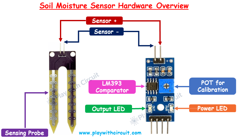
The Sensing Probe
The sensor consists of a fork-shaped sensing probe with two exposed conductors. The probe is inserted into the soil to measure the moisture content. Its resistance varies according to soil moisture. It has two Header pins which are used to connect the probes to the sensor module through jumper wires.
Sensor Module
The sensor module connects the probe to the Arduino. It has the following key components:
LM393 IC LM393 Comparator IC is used as a voltage comparator in this module. Positive Input of the comparator is connected to the Positive terminal of the probe and negative input of the comparator is connected to the middle pin of the POT.
Potentiometer (Trimpot) The module has a 10k Trimpot or potentiometer which is used to adjust the sensitivity of the sensor by rotating the knob. If we rotate the knob in the clockwise direction, the module sensitivity will increase. The module sensitivity will decrease if we rotate it in an anti-clockwise direction.
Power LED When we provide the power supply to the sensor, this LED turns ON.
Output LED When the sensor detects the soil moisture, the LED turns on. When it does not detect any moisture in the soil, the LED turns off.
❕Note
There are two types of soil moisture sensors: resistive and capacitive. FC-28 is a resistive type of soil moisture sensor.
Soil Moisture Sensor Pinout
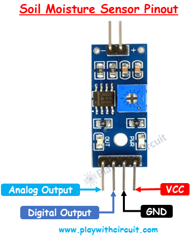
The module board typically has four pins:
VCC This is the power supply pin that can be connected to the positive supply voltage, usually 3.3V or 5V.
GND This is the ground pin and it should be connected to the ground pin of the Arduino.
DO (Digital Output) This pin produces a digital output signal (HIGH or LOW) based on the soil moisture level. Output HIGH indicates soil moisture is low, Output LOW indicates soil moisture is appropriate.
AO (Analog Output) This pin generates an analog output voltage that varies with the soil moisture level.
Schematic Diagram of the Sensor Module
The internal Circuit diagram of the sensor module is given below:
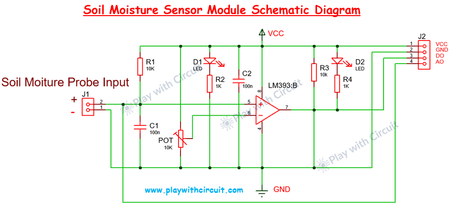
The main component of the Module is the comparator IC LM 393. This IC compares the voltage at its negative terminal with the voltage at its positive terminal which is connected to the sensor. The Ground of the comparator is connected to the negative terminal of the probe.
When the soil is moist the voltage at the positive terminal of the comparator becomes less than the voltage at the negative terminal and hence output becomes LOW due to which output LED glows.
Similarly, when the soil is dry the voltage at the positive terminal of the comparator becomes higher than the voltage at the negative terminal as it is pulled up hence output remains HIGH, and LED remains off.
How to Calibrate the Soil Moisture sensor
-
Firstly, put the sensor probe in dry soil.
-
If the output LED is ON then rotate the POT in an Anti-clockwise direction till the LED turns OFF.
-
Now put the sensor probe in wet soil. If the output LED is ON then it is OK else rotate the POT in the clockwise direction slowly till the output LED turns ON.
Interfacing Soil Moisture Sensor with Arduino Uno
In this section, first we will connect the sensor with the arduino in analog mode to read the analog output and then in digital mode to read the digital output.
Hardware and Software Requirements
Hardware Requirement
| Component Name | Quantity | Remarks | Where to Buy |
|---|---|---|---|
| Arduino UNO R3 | 1 | Revision R3 | Amazon.com / Amazon.in / Banggood |
| Soil Moisture sensor | 1 | FC-28, resistive type | Amazon.com / Amazon.in |
| LCD 16x2 | 1 | I2C support | Amazon.com / Amazon.in / Banggood |
| Jumper Wires | 10 | For Arduino and Sensor connections | Amazon.com / Amazon.in / Banggood |
| Breadboard | 1 | Full size | Amazon.com / Amazon.in / Banggood |
| USB Cable Type A to B | 1 | for programming Arduino UNO | Amazon.com / Amazon.in |
| 12V Supply Adapter | 1 | For providing power to Arduino | Amazon.com / Amazon.in / Banggood |
Software Requirement
Arduino IDE, Version 2.1.1 or above installed on your PC
Wiring Soil Moisture Sensor in Analog Mode
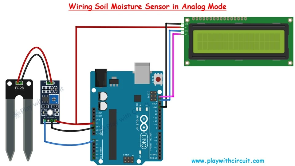
In the above wiring diagram, Arduino UNO is connected to a soil moisture sensor. The VCC and ground to the sensor are connected with the VCC and GND of the Arduino, respectively. The Analog output line of the sensor is connected to the analog input pin A0 of Arduino. A 16×2 I2C LCD is connected at the SCL and SDA pin of the Arduino
Arduino Code
/*
Interfacing FC-28 Soil Moisture Sensor with Arduino UNO using is Analog Output pin of Module
by www.playwithcircuit.com
*/

// Library to Run I2C LCD
#include <LiquidCrystal_I2C.h>

// Set the LCD address to 0x27 for a 16 chars and 2 line display
LiquidCrystal_I2C lcd(0x27, 16, 2);

// Define the analog pin for the soil moisture sensor
const int soilMoisturePin = A0;

// Variables to store sensor values
int sensorValue = 0;
int moisturePercent = 0;

void setup()
  {
  // initialize the lcd
  lcd.init();
  // Turn on the Backlight
  lcd.backlight();
  // Clear the display buffer
  lcd.clear();
  // Print a message to the LCD
  lcd.setCursor(0, 0);
  lcd.print("Soil Moisture:");
}

void loop()
  {
  // Read the value from the soil moisture sensor
  sensorValue = analogRead(soilMoisturePin);

  // Convert the sensor value to percentage
  moisturePercent = map(sensorValue, 0, 1020, 100, 0);

  // Display the moisture percentage on the LCD
  lcd.setCursor(0, 1);
  lcd.print(moisturePercent);
  lcd.print(" %  "); // Clear any extra characters

  // Wait for 1 second
  delay(1000);
}
Code Description
First we include the library for the I2C LCD and then create an object, specifying the I2C address (0x27) and the size of the display (16 characters and 2 lines).
#include <LiquidCrystal_I2C.h>
// Set the LCD address to 0x27 for a 16 chars and 2 line display
LiquidCrystal_I2C lcd(0x27, 16, 2);
Now we define the analog pin A0 as the input pin for the soil moisture sensor. And declare two variables: sensorValue to store the raw sensor reading and moisturePercent to store the converted moisture percentage.
// Define the analog pin for the soil moisture sensor
const int soilMoisturePin = A0;

// Variables to store sensor values
int sensorValue = 0;
int moisturePercent = 0;
In the setup function, the LCD is initialized and the message “Soil Moisture:” is printed on the first line of the LCD to indicate what is being measured.
void setup()
{
  // initialize the lcd
  lcd.init();
  // Turn on the Backlight
  lcd.backlight();
  // Clear the display buffer
  lcd.clear();
  // Print a message to the LCD
  lcd.setCursor(0, 0);
  lcd.print("Soil Moisture:");
}
In the loop function, the analog value from the soil moisture sensor is read and stored in sensorValue.
The raw sensor value, which ranges from 0 to 1020, is converted to a percentage. This mapping function converts the raw value to a percentage between 0% (completely dry) and 100% (completely wet).
The moisture percentage is displayed on the second line of the LCD. The additional spaces (” % “) ensure that any leftover characters from previous values are cleared.
The delay(1000); function pauses the loop for 1 second before repeating, ensuring the display updates once per second.
void loop() {
  // Read the value from the soil moisture sensor
  sensorValue = analogRead(soilMoisturePin);

  // Convert the sensor value to percentage
  moisturePercent = map(sensorValue, 0, 1020, 100, 0);

  // Display the moisture percentage on the LCD
  lcd.setCursor(0, 1);
  lcd.print(moisturePercent);
  lcd.print(" %  "); // Clear any extra characters

  // Wait for 1 second
  delay(1000);
}
Wiring Soil Moisture sensor in Digital Mode
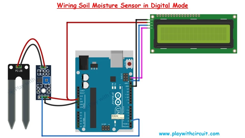
The main difference between the previous wiring diagram and this one is that here we are using the digital output pin of the Sensor.
Arduino Code
/*
Interfacing FC-28 Soil Moisture Sensor with Arduino UNO using is Digital Output pin of Module
by www.playwithcircuit.com
*/

#include <LiquidCrystal_I2C.h>
// Library to Run I2C LCD

// Set the LCD address to 0x27 for a 16 chars and 2 line display
LiquidCrystal_I2C lcd(0x27, 16, 2);

// Define the digital pin for the soil moisture sensor
const int soilMoisturePin = 2;

// Variable to store Output
int sensorOutput = 0;

void setup() {
  // initialize the lcd
  lcd.init();
  // Turn on the Backlight
  lcd.backlight();
  // Clear the display buffer
  lcd.clear();

  // Initialize the digital pin as an input
  pinMode(soilMoisturePin, INPUT);

  // Print a message to the LCD
  lcd.setCursor(0, 0);
  lcd.print("Soil Moisture:");
}

void loop() {
  // Read the value from the soil moisture sensor
  sensorOutput = digitalRead(soilMoisturePin);

  // Display the moisture status on the LCD
  lcd.setCursor(0, 1);
  if (sensorOutput == HIGH) {
    lcd.print("Dry");
  } else {
    lcd.print("Wet");
  }

  // Wait for 1 second
  delay(1000);
}
Common Problems while using the Soil Moisture Sensor
While using the soil moisture sensor for longer durations most common problem is
- The rust on the sensor probe.
- The deposition formation on the probe.
- Power consumption is more.
The rust problem can be resolved by using a good-quality sensor. The deposition occurs because continuous current is flowing through the probe. To resolve power and deposition issues the sensor power must be controlled through the Arduino. As the current consumption of the sensor is less than the source current of Arduino’s Digital output pin(40mA max), hence it could be powered through the Digital pin of the Arduino and when the Arduino is in the wait state the power to the sensor must be turned off and the Arduino Should be put in the Low power mode for the wait time. For low-power modes, we need to install the Low-power library by Arduino.
Installing Low Power Library
This library enables us to put Arduino in Idle/sleep mode.
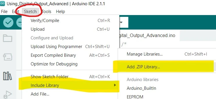
To install the Arduino Low Power library, you can follow these steps:
- Download the Library from here: Low Power Library
- Open Arduino IDE.
- Navigate to Sketch > Include Library > Add .ZIP Library
- Go to the folder when .ZIP file is downloaded.
- Select file Low-Power-master.zip.
Note: This library is not owned by Play with Circuit.
Wiring Diagram in Low-Power Digital Mode
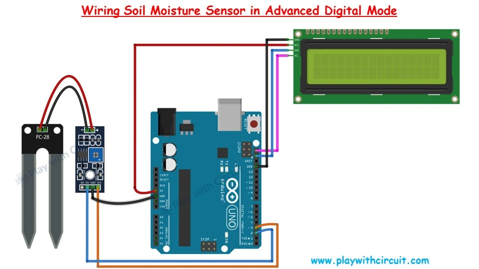
The main difference between the previous wiring diagram in digital mode and this wiring diagram is that here we are using the digital output pin 3 of the Arduino to power the sensor.
Arduino Code
/*
Interfacing FC-28 Soil Moisture Sensor with Arduino UNO
by www.playwithcircuit.com
*/

// Library to Run I2C LCD
#include <LiquidCrystal_I2C.h>
#include <LowPower.h>

// idle timer in seconds it can be increased to max 65535
#define IDLE_TIME_IN_SECONDS 10

// Set the LCD address to 0x27 for a 16 chars and 2 line display
LiquidCrystal_I2C lcd(0x27, 16, 2);

// Define the digital pin for the soil moisture sensor
const int soilMoisturePin = 2;

// Define the power pin for the soil moisture sensor
const int soilMoisturePowerPin = 3;
// Variable to store Output
int sensorOutput = 0;
// Index for idle time counter
int idleTimeCounter = 0;

void setup() {
  // initialize the lcd
  lcd.init();
  // Turn on the Backlight
  lcd.backlight();
  // Clear the display buffer
  lcd.clear();

  // Initialize the digital pin as an input
  pinMode(soilMoisturePin, INPUT);

  // Initialize the power pin as an OUTput
  pinMode(soilMoisturePowerPin, OUTPUT);

  // Print a message to the LCD
  lcd.setCursor(0, 0);
  lcd.print("Soil Moisture:");
}

void loop() {
  // Turn on the Backlight
  lcd.backlight();
  // Turn Power of soil sensor ON
  digitalWrite(soilMoisturePowerPin, HIGH);
  delay(10);  // power stable delay
  // Read the value from the soil moisture sensor
  sensorOutput = digitalRead(soilMoisturePin);

  // Display the moisture status on the LCD
  lcd.setCursor(0, 1);
  if (sensorOutput == HIGH) {
    lcd.print("Dry");
  } else {
    lcd.print("Wet");
  }
  // Turn Power of soil sensor OFF
  digitalWrite(soilMoisturePowerPin, LOW);
  // this delay can be reduced as per required, its the time for which LCD is ON , it can be reduced to zero
  delay(1000);
  lcd.noBacklight();
  for (idleTimeCounter = 0; idleTimeCounter < IDLE_TIME_IN_SECONDS; idleTimeCounter++) {
    // Enter low power mode for 1 second
    LowPower.idle(SLEEP_1S, ADC_OFF, TIMER2_OFF, TIMER1_OFF, TIMER0_OFF,
                  SPI_OFF, USART0_OFF, TWI_OFF);
    delay(1000);
  }
}