The LM35 is one of the most widely used temperature sensors due to its ease of use and affordability. It gives a linear voltage output and does not require any external calibration and signal conditioning. It is a perfect option to add temperature sensing to your Arduino project.
In this tutorial, we will learn how to connect the LM35 with an Arduino UNO. We will also create a temperature monitoring system that measures and displays the temperature in both Celsius and Fahrenheit. The readings will be updated in real-time and shown on a 16×2 LCD.
LM35 Temperature Sensor
The LM35 is a precision analog temperature sensor that provides a linear output voltage proportional to the temperature in °C. The sensor operates on a wide voltage range of 4V to 30V and consumes only 60 μA of current, resulting in minimal self-heating.
One of the primary advantages of the LM35 is that its linear output simplifies interfacing with ADCs or microcontrollers like Arduino without the need for additional components. With its 10mV/°C linear scale, converting the output voltage into temperature readings is straightforward. However, when paired with an 8-bit ADC (like ADC0808 or ADC0804), an amplifier might be required for precise 1°C measurements.
However, the LM35 does have some limitations. The LM35 cannot directly measure negative temperatures. It cannot directly measure negative temperatures without a dual-polarity power supply. For such applications, the TMP36 sensor, which supports negative temperature measurement, is a better alternative. Additionally, being an analog sensor, the LM35 is sensitive to electrical noise, which can affect performance in long-distance or noisy environments. In such cases, digital sensors like the DS18B20 are more reliable.
Specification of LM35 Temperature Sensor
- Operating voltage: 4 V to 30 V
- Operating temperature range (°C): -55 to 150
- Current drawn: 60 μA (typical)
- Output type: Analog
- Accuracy: ±0.5°C (typical)
- Low impedance output: 0.1Ω for 1 mA load
- Linearity: ±0.25°C
- Sensitivity: 10 mV/°C

How does the LM35 Temperature Sensor Work?
The LM35 works by using matched transistors to generate a voltage difference that varies linearly with temperature. This voltage is amplified and buffered to provide a clean analog voltage output that represents temperature in Celsius directly without needing calibration or additional circuitry.
Here is the block diagram:
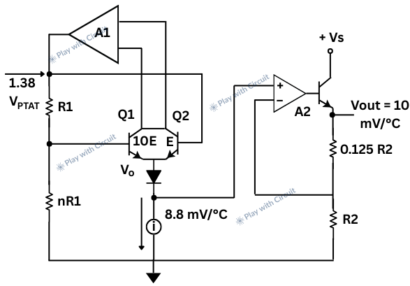
In the above block diagram there are two identical BJT Q1 and Q2. The current flowing through Q1 is 10 times the current through Q2. This is done intentionally using resistors and current mirrors in the circuit.
This unequal current density creates a difference in how the two transistors behave, especially in their base-emitter voltages (VBE).
Because Q1 and Q2 carry different currents, the voltage across their base-emitter junctions (VBE) is different.
This difference is given by:
ΔVBE = VBE1 – VBE2 = (kT/q) * ln(I1 / I2)
Where,
I1 / I2= 10 in this case,
T is the absolute temperature (in Kelvin),
k and q are physical constants.
So, this ΔVBE is directly proportional to Absolute temperature T (PTAT)
It means as the temperature rises, ΔVBE increases in a linear manner with temperature.
This PTAT voltage is then scaled to give an output voltage that increases 10 mV per °C.
So,
- At 0°C → Output = 0 mV
- At 25°C → Output = 250 mV
- At 100°C → Output = 1.00 V
LM35 Temperature Sensor Pinout
The LM35 has three pins:
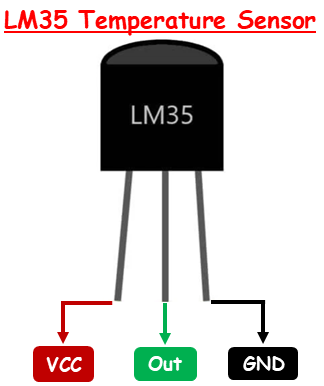
VCC (Power Supply) This is the power supply pin of the LM35. It can be connected to a supply voltage between 4V – 30V.
GND This is the ground pin.
Out This is the analog output pin of the sensor.
How to Measure Temperature with LM35?
To measure temperature using the LM35 sensor, connect the left pin to a power source (4V and 30V), the right pin to ground. Then the middle pin will provide analog voltage linearly proportional to the temperature in °C with a scale factor of 10 mv/°C.
Thus, the analog output voltage is: Vout = 10 mv/°C × T
Hence, temperature can be calculated as T = Vout * 100
For example, an output voltage of 0.1V corresponds to 10°C.
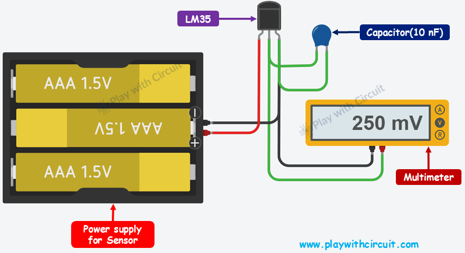
You can test the LM35 using a multimeter. Set your multimeter to DC voltage mode and attach its negative probe to the ground (pin 3) and its positive probe to the middle pin (output).
Provide supply at Vcc pin (pin 1). At room temperature, which is approximately 25°C, the sensor should output a voltage of about 250mV.
Wiring LM35 Temperature Sensor with an Arduino
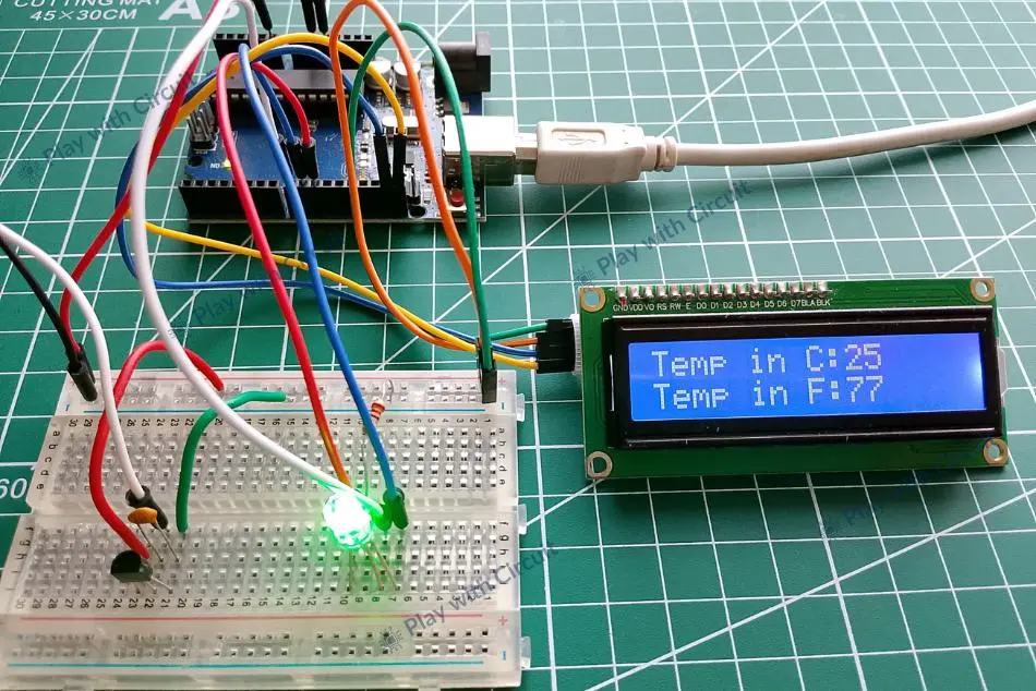
Now let’s start wiring an LM35 temperature sensor with Arduino to display temperature in Fahrenheit and in degrees Celsius on I2C LCD. We will use one RGB LED that will indicate the current temperature by changing colors—red for high, green for normal, and blue for low.
Hardware Requirement
| Component Name | Quantity | Remarks | Where to Buy |
|---|---|---|---|
| Arduino UNO R3 | 1 | Revision R3 | Amazon |
| LM35 Temperature Sensor | 1 | For measauring temperature | Amazon |
| Resistance | 1 | 220 Ω | Amazon |
| Breadboard | 1 | Half size | Amazon |
| RGB LED | 1 | Common Cathode | Amazon |
| Jumper Wires | 1 | For connections | Amazon |
| USB Cable Type A to B | 1 | for programming Arduino UNO | Amazon |
| 12V Supply Adapter | 1 | For providing power to Arduino | Amazon |
Software Requirement
- Arduino IDE, Version 2.3.4 or above installed on your PC.
- LiquidCrystal_I2C Library by Frank de Brabander V 1.1.2
Wiring Diagram
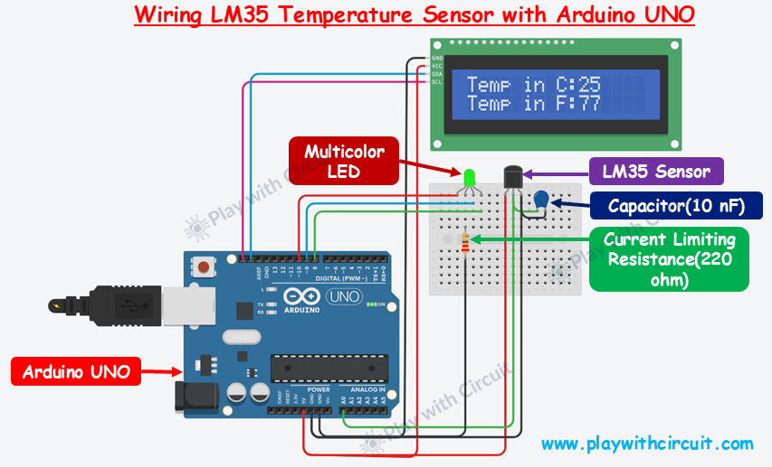
In the above wiring diagram, the temperature sensor Analog output pin is connected to Analog input pin A0 of the Arduino, power pin to Vcc pin and GND pin is connected with 5V Arduino pin. The wiring is done in such a way that it can only measure positive temperatures.
A 10 nF capacitor is also connected at the output pin of the temperature sensor for stable readings.
Here a common cathode RGB LED is used whose Red, Blue and Green Anode legs are connected to pin 10, 9 and 8 pins of Arduino UNO. The Cathode of LED is connected to GND via current limiting resistance.
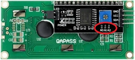
A PCF8574 based I2C LCD is also added to display temperature. SCL(clock) and SDA(data) pins of I2C LCD are connected to SCL and SDA pins of Arduino. SCL and SDA pins are the same as pins A5 and A4 Analog input pins of Arduino. Hence while using the I2C peripheral of Arduino do not use Analog input functionality at pin A4 or A5 pin. The power to the LCD is provided using the 5V and GND pins of the Arduino.
Make sure A0, A1, A2 address jumpers are not shorted when using I2C LCD. As in code we will be using Address 0x27 for the I2C LCD which will only be formed when these jumpers are not shorted in the I2C LCD. When all of these pins are shorted the address will become 0x20.
Arduino Code for wiring the LM35 Temperature Sensor with Arduino
Upload the folllowing code to your Arduino.
/*
Interfacing temperature Sensor with Arduino UNO using Analog input pin of Arduino and
display temperature in Fahrenheit and in degree Celsius on I2C LCD. Here RGB LED turns Blue at LOW temperature, Red at HIGH temperature and Green when the temperature is between LOW and HIGH limit.
by www.playwithcircuit.com
*/

#include <LiquidCrystal_I2C.h>  // Library to Run I2C LCD

#define RED_PIN 10
#define BLUE_PIN 9
#define GREEN_PIN 8

#define LOW_TEMP    10
#define HIGH_TEMP   50
// Set the LCD address to 0x27 for a 16 chars and 2 line display
LiquidCrystal_I2C lcd(0x27, 16, 2);

// Define the analog pin for the temperature sensor
const int TemperatureSensorPin = A0;

// Variable to store the Analog count from temperature sensor
int temperatureCounts;

// Variable to store Voltage values
float voltageValue;

// Variable to store Temperature in Degree Celsius
float temperatureDegreeCelsius;

// Variable to store Temperature in Fahrenheit
float temperatureFahrenheit;

void setup() {
  // initialize the lcd
  lcd.init();
  // Turn on the Backlight
  lcd.backlight();
  // Clear the display buffer
  lcd.clear();
  // Make LED pins and Buzzer pin as output
  pinMode(RED_PIN, OUTPUT);
  pinMode(BLUE_PIN, OUTPUT);
  pinMode(GREEN_PIN, OUTPUT);

  // Turn off all the pins
  digitalWrite(RED_PIN, LOW);
  digitalWrite(BLUE_PIN, LOW);
  digitalWrite(GREEN_PIN, LOW);

  // Print a message to the LCD
  lcd.setCursor(0, 0);
  lcd.print("Initializing");

  // Print a message to the LCD
  lcd.setCursor(0, 1);
  lcd.print("Please Wait...");

  // flush out the first hundred values give time to temperature sensor to be stable
  for (int i = 0; i < 100; i++) {
    // Read the value from the temperature sensor
    temperatureCounts = analogRead(TemperatureSensorPin);
    delay(10);
  }
  // Clear the display buffer
  lcd.clear();

  // Print a message to the LCD
  lcd.setCursor(0, 0);
  lcd.print("Temp in C:");

  // Print a message to the LCD
  lcd.setCursor(0, 1);
  lcd.print("Temp in F:");
}

void loop() {
  // Static variables to save the last temperature
  static float lastTemp = 0xFF;

  // Read the value from the temperature sensor
  temperatureCounts = analogRead(TemperatureSensorPin);

  // convert the counts 0 to 1023 into voltage values 0 to 5V
  voltageValue = (5.0/1023) * temperatureCounts;

  // Convert voltage to temperature in Celsius
  temperatureDegreeCelsius = voltageValue * 100;

  // Convert Celsius to Fahrenheit
  temperatureFahrenheit = (temperatureDegreeCelsius * 9.0 / 5.0) + 32.0;

  // If current temperature is not equal to last temperature value in degree celsius
  if (lastTemp !
= temperatureDegreeCelsius) {
    // Print a temp to the LCD
    lcd.setCursor(10, 0);
    lcd.print("      ");
    lcd.setCursor(10, 0);
    lcd.print((int)temperatureDegreeCelsius);

    // Print a message to the LCD
    lcd.setCursor(10, 1);
    lcd.print("      ");
    lcd.setCursor(10, 1);
    lcd.print((int)temperatureFahrenheit);
  }

  // Save the current temperature value in the static variable to use it later
  lastTemp = temperatureDegreeCelsius;

  // Change the color of LED as per temperature level
  if (temperatureDegreeCelsius > HIGH_TEMP) {
    digitalWrite(RED_PIN, HIGH);
    digitalWrite(BLUE_PIN, LOW);
    digitalWrite(GREEN_PIN, LOW);
  } else if (temperatureDegreeCelsius >= LOW_TEMP && temperatureDegreeCelsius <= HIGH_TEMP) {
    digitalWrite(RED_PIN, LOW);
    digitalWrite(BLUE_PIN, LOW);
    digitalWrite(GREEN_PIN, HIGH);
  } else if (temperatureDegreeCelsius < LOW_TEMP) {
    digitalWrite(RED_PIN, LOW);
    digitalWrite(BLUE_PIN, HIGH);
    digitalWrite(GREEN_PIN, LOW);
  }

  // Wait for 1000 ms before the next loop
  delay(1000);
}
Code Description
The sketch begins by including the LiquidCrystal_I2C library, which provides a set of functions to control an LCD via I2C protocol.
#include <LiquidCrystal_I2C.h> // Library to Run I2C LCDNow we define the digital pins which are connected to the Red, Blue, and Green pins of the RGB LED.
#define RED_PIN 10
#define BLUE_PIN 9
#define GREEN_PIN 8
Then, we define temperature limits (in °C):
- If temp < 10°C → RGB Led turns Blue
- If 10°C ≤ temp ≤ 50°C → RGB Led turns Green
- If temp > 50°C → RGB Led turns Red
#define LOW_TEMP    10
#define HIGH_TEMP   50
Next, we create an LCD object with I2C address: 0x27 (default for most 16×2 I2C LCDs), 16 characters per line, 2 lines.
Then we define the Analog Input pin A0 of Arduino which is connected to the temperature sensor LM35.
// Set the LCD address to 0x27 for a 16 chars and 2 line display
LiquidCrystal_I2C lcd(0x27, 16, 2);

// Define the analog pin for the temperature sensor
const int TemperatureSensorPin = A0;
Next we define following variables:
- temperatureCounts It stores the raw analog value (0–1023) read from the temperature sensor.
- voltageValue This variable is used to store the voltage equivalent of the raw analog count.
- temperatureDegreeCelsius It stores the temperature in degrees Celsius.
- temperatureFahrenheit It holds the temperature value in Fahrenheit.
// Variable to store the Analog count from temperature sensor
int temperatureCounts;

// Variables to store Voltage values
float voltageValue;

// Variable to Store Temperature in Degree Celsius
float temperatureDegreeCelsius;

// Variable to Store Temperature in fahrenheit Celsius
float temperatureFahrenheit;
In the setup, first we initialise the LCD, then turn on its backlight and clear any existing content.
Next we configure the Arduino’s digital pins connected to an RGB LED as output pins using pinMode() function.
Here, RED_PIN, BLUE_PIN and GREEN_PIN are configured as output pins to control the red, blue and green light of RGB LED. Initially these pins are turned off using digitalWrite().
void setup() {
  // initialize the lcd
  lcd.init();
  // Turn on the Backlight
  lcd.backlight();
  // Clear the display buffer
  lcd.clear();
  // Make LED pins and Buzzer pin as output
  pinMode(RED_PIN, OUTPUT);
  pinMode(BLUE_PIN, OUTPUT);
  pinMode(GREEN_PIN, OUTPUT);

  // Turn Off all the pins
  digitalWrite(RED_PIN, LOW);
  digitalWrite(BLUE_PIN, LOW);
  digitalWrite(GREEN_PIN, LOW);
Next, the LCD displays a message “Initializing” and “Please Wait…” to indicate that setup is in progress.
  // Print a message to the LCD
  lcd.setCursor(0, 0);
  lcd.print("Initializing");

  // Print a message to the LCD
  lcd.setCursor(0, 1);
  lcd.print("Please Wait...");
To stabilize the temperature sensor readings, the code reads analog data from the sensor pin 100 times with a 10-millisecond delay between each read. These initial readings are discarded to give the sensor time to settle.
After this, the LCD is cleared again, and it displays two placeholder messages: “Temp in C:” and “Temp in F:”, for showing temperature values in Celsius and Fahrenheit, which will be updated in the main loop function.
// flush out the first hundred values give time to temperature sensor to be stable
  for (int i = 0; i < 100; i++) {
    // Read the value from the temperature sensor
    temperatureCounts = analogRead(TemperatureSensorPin);
    delay(10);
  }
  // Clear the display buffer
  lcd.clear();

  // Print a message to the LCD
  lcd.setCursor(0, 0);
  lcd.print("Temp in C:");

  // Print a message to the LCD
  lcd.setCursor(0, 1);
  lcd.print("Temp in F:");
}
At the beginning of the loop function, we use a variable lastTemp to store the previously recorded temperature in Celsius. This helps avoid unnecessary LCD updates if the temperature hasn’t changed.
The sensor value is read using analogRead(), which gives a value between 0 and 1023. This raw value is then converted into voltage. The voltage is multiplied by 100 to get the temperature in Celsius. The Celsius value is further converted to Fahrenheit using the standard formula.
void loop() {
  // Static variables to save the last temperature
  static float lastTemp = 0xFF;

  // Read the value from the temperature sensor
  temperatureCounts = analogRead(TemperatureSensorPin);

  // convert the counts 0 to 1023 into voltage values 0 to 5V
  voltageValue = (5.0/1023) * temperatureCounts;

  // Convert voltage to temperature in Celsius
  temperatureDegreeCelsius = voltageValue * 100;

  // Convert Celsius to Fahrenheit
  temperatureFahrenheit = (temperatureDegreeCelsius * 9.0 / 5.0) + 32.0;
If the current temperature differs from the last recorded value, the LCD is updated by first clearing the existing temperature reading and then printing the new values.
 // If current temperature is not equal to last temperature value in degree celsius
  if (lastTemp != temperatureDegreeCelsius) {
    // Print a temp to the LCD
    lcd.setCursor(10, 0);
    lcd.print("      ");
    lcd.setCursor(10, 0);
    lcd.print((int)temperatureDegreeCelsius);

    // Print a message to the LCD
    lcd.setCursor(10, 1);
    lcd.print("      ");
    lcd.setCursor(10, 1);
    lcd.print((int)temperatureFahrenheit);
  }
First, the current temperature in Celsius is saved into the lastTemp variable.
Next, the LED color is set according to the temperature:
- If the temperature is above HIGH_TEMP, the LED turns red.
- If the temperature falls between LOW_TEMP and HIGH_TEMP, the LED glows green, signaling that the temperature is within the normal range.
- If the temperature is below the LOW_TEMP, the RGB LED emits a blue color, representing a low temperature.
A short delay of 1000 milliseconds at the end of the loop ensures smooth operation and limits how fast the loop runs.
 // Save the current temperature value in the static variable to use it later
  lastTemp = temperatureDegreeCelsius;

  // Change the color of LED as per temperature level
  if (temperatureDegreeCelsius > HIGH_TEMP) {
    digitalWrite(RED_PIN, HIGH);
    digitalWrite(BLUE_PIN, LOW);
    digitalWrite(GREEN_PIN, LOW);
  } else if (temperatureDegreeCelsius >= LOW_TEMP && temperatureDegreeCelsius <= HIGH_TEMP) {
    digitalWrite(RED_PIN, LOW);
    digitalWrite(BLUE_PIN, LOW);
    digitalWrite(GREEN_PIN, HIGH);
  } else if (temperatureDegreeCelsius < LOW_TEMP) {
    digitalWrite(RED_PIN, LOW);
    digitalWrite(BLUE_PIN, HIGH);
    digitalWrite(GREEN_PIN, LOW);
  }

  // Wait for 1000 ms before the next loop
  delay(1000);
}
💡Must Read
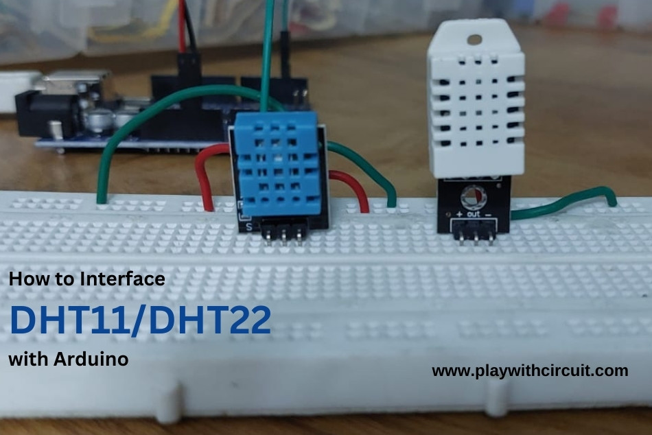
Interface DHT11 and DHT22 Sensors with Arduino Uno
Need both temperature and humidity data in your project? Explore this guide to learn how to connect DHT11 and DHT22 sensors with Arduino.
FAQ’S
What are the advantages of using the LM35?
- It’s factory-calibrated for Celsius measurements so no calibration is required.
- It is highly sensitive which means a small change in temperature results in a measurable change in output voltage.
- It has a small form factor and robust design.
What are common applications of the LM35?
- HVAC systems (Heating, Ventilation, and Air Conditioning).
- Industrial temperature monitoring.
- Home automation for temperature control.
- Battery temperature monitoring.
- Weather stations.
What are alternatives to the LM35 for measuring negative temperatures?
Use sensors like the TMP36 (handles negative temperatures without negative voltages), DS18B20 (digital output with wide range), or LM335 (absolute temperature sensor). Thermistors or RTDs can also be used for broader temperature ranges.
How can I improve the stability of LM35 readings in a noisy electrical environment?
To improve LM35 stability in noisy environments, use decoupling capacitors (0.1 µF and 10 µF) to filter noise, keep wires short or shielded, and add a pull-down resistor (10 kΩ) at the output. Employ low-pass filters, signal averaging, and proper grounding, and position the sensor away from high-power components to reduce interference.