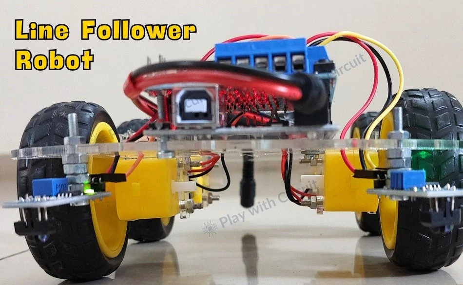
A line follower robot or LFR is an autonomous guided robot that follows a predetermined path marked by usually a black line on a white surface or a white line on a black surface. These robots are widely used in industrial automation, warehouse logistics, and educational purposes.
This comprehensive guide includes everything you need to know to build and operate an Arduino-based line follower robot. Let’s get started!
Working of a Line Follower Robot
As we mentioned earlier, the line follower robot detects the black line and moves along that line. But how do we implement the line-detecting mechanism in LFR? We know that black surfaces absorb the most light, while white surfaces reflect almost all the light. This property of light is used by many sensors such as LDR (light-dependent resistor), IR Sensors or Line sensors to detect the line. Here we are using Line sensors for high precision and accurate detection of lines.
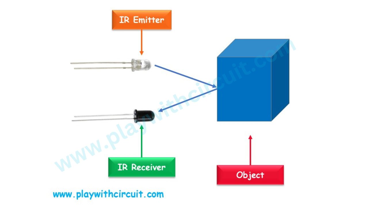
Line sensors usually consist of an IR emitter (LED) and an IR receiver (photodiode). The emitter continuously emits infrared light, and the receiver detects the reflected light.
When the IR light emitted by the emitter falls on the white surface, it reflects back and is detected by the receiver. When the light hits the black line, it gets absorbed and doesn’t reach the receiver. The following figure shows the working of the Line sensor.
How does a Line Follower Robot Navigates?
In order to add navigation functionality to the Robot we need two motors. One motor is placed on the left side and another on the right side of the chassis. The motor’s direction of rotation is controlled by the signals received from sensors positioned on the left and right sides.
There are four possible cases in which the robot can move:
Case 1: When Robot Moves Forward
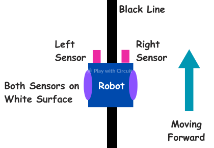
When both sensors are on the white surface which means they don’t detect the line (the black line is between them), the robot should move in the forward direction. In this case, both motors rotate in the forward direction causing the robot to move in the forward direction.
Case 2: When Robot Turns to Left
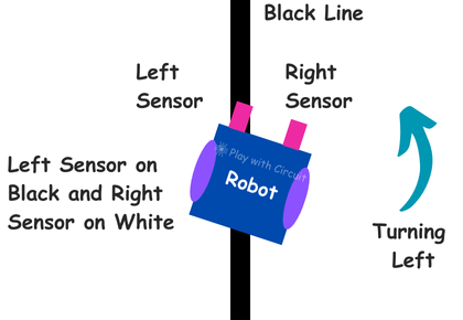
When the right sensor is on the white surface and the left sensor detects the black line, it gives a signal to the microcontroller. So the robot should turn to the left. Thus the left motor rotates backward while the right motor continues to move forward. As a result, the robot turns to the left.
Case 3: When Robot Turns to Right
If the left sensor is on the white surface and the right sensor detects the line, it sends a signal to the microcontroller. So the robot should turn right. Therefore, the left motor moves forward while the right motor moves backward so the robot moves to the right.
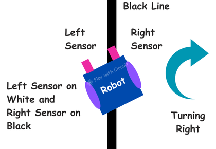
Case 4: When Robot stops
When both sensors simultaneously detect the black line, the robot should stop. Thus, both motors cease movement causing the robot to stop.
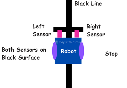
Hardware and Software Requirements
Hardware Requirements
| Component Name | Quantity | Where to Buy |
|---|---|---|
| Arduino UNO R3 | 1 | Amazon.com / Amazon.in / Banggood |
| L293D Motor Driver Shield | 1 | Amazon.com / Amazon.in |
| Jumper wires | Multiple | Amazon.com / Amazon.in / Banggood |
| USB A to B cable | 1 | Amazon.com / Amazon.in |
| Robot Chassis, Wheels, Geared Motors(Kit) | - | Amazon.com / Amazon.in |
| Line Sensor Module | 2 | Amazon.com / Amazon.in / Banggood |
| Black Tape | 1 | Amazon.com / Amazon.in |
You can either purchase above components individually or purchase a DIY Line Follower Robot Kit which usually includes all the required components.
Software Required
- Arduino IDE, Version 2.1.1 or above installed on your PC
- Adafruit Motor Shield Library(V1) by Adafruit version 1.0.1.
Why do we need an L293D Motor Driver Shield?
Here we need to use an L293D motor driver shield because dc motors used in robot require higher voltage and current than what Arduino can provide directly. The motor driver can handle the higher power requirements safely, preventing damage to the Arduino.
Also, it allows bi-directional control, enabling the motor to rotate in both forward and reverse direction.
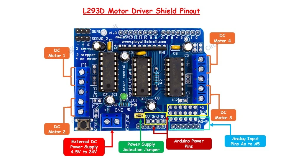
To know more about the L293d motor driver shield and Adafruit Library functions, which is used to control the motors using the shield, check out this tutorial: L293D Motor Driver Shield Tutorial
Circuit Diagram of Line Follower Robot
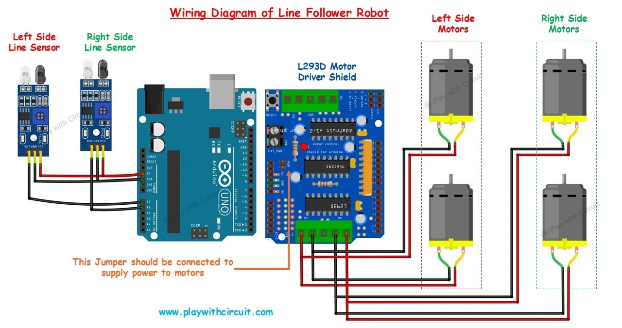
The circuit consists of four parts: Two IR sensors, one L293D motor driver, four 12 Volt BO motors, and one Arduino Board. A 12V supply is not shown here but will be connected to the Arduino. The shield need to be placed on the top of the Arduino board.
The VCC and Ground pins of sensors are connected to VCC and Ground pins of Arduino.
The analog output pin of the left IR sensor or Line sensor is connected to the Analog input A0 and the Analog output pin of the right Line sensor is to be connected to Analog input pin A1 of the Arduino.
The left-side motors are parallelly connected to the port M3 of the motor driver shield and the right-side motors are parallelly connected to the port M4 of the motor driver shield.
❕Note
When updating the code while the motor driver and motors are connected to the Arduino board, it’s important to follow safety precautions. Before connecting the USB cable for programming, disconnect the power jumper on the motor driver shield and remove the external 12V power supply from the Arduino.
Once the programming is complete, unplug the USB cable, reconnect the 12V power supply to the Arduino, and then reconnect the power jumper on the shield. This ensures the safety of the components and prevents potential damage during the coding process.
Assembling the Arduino-based Line Follower Robot
Now we understand all the connections, we can start assembling our robot. We have explained the step-by-step process of assembling the robot in the video provided at the end.
Step 1 To build the robot, first you’ll need a chassis. Here we are using readymade chassis. Then solder all the four motors with at least 15 cm wires.
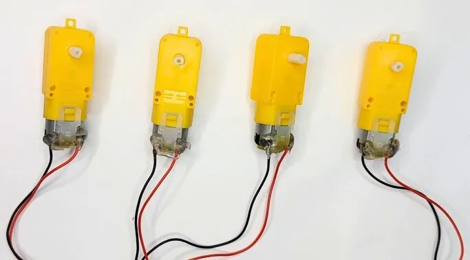
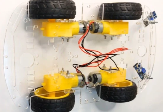
Step 2 Now remove the protecting cover of the chassis and attach all the four motors, both line sensors and wheels to the chassis. Then connect red wires of the of left-hand side motors (front and rear) and black wires of right hand side motors (front and rear). Similarly do this for right-hand side motors also.
The center-to-center distance between the two line sensors should be 11 to 11.5 cm. This distance is critical for accurate line detection and smooth navigation along the black tape.
The distance between the sensor’s LED (the part of the sensor closest to the ground) and the flat surface should be maintained at exactly 2 cm.
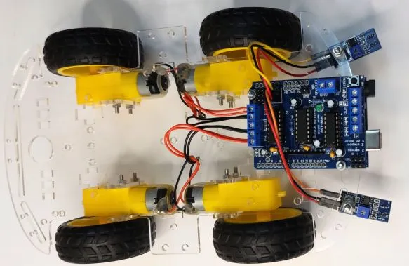
Step 3 Next, attach the motor driver shield with the Arduino Uno board and place it on the chassis using double-sided tape or mounting screws. Ensure that it is securely fastened and positioned in front for easy access to other components.
Then make the connections of the line sensors and motors with the shield as per circuit diagram. The left-side motors should be connected to the port M3 of the motor driver shield and right-side motors are connected to the port M4 of the shield.
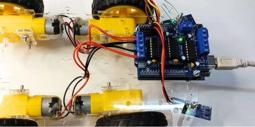
Step 4 Next, program the Arduino UNO. Make sure the PWR jumper is not connected on the Motor driver shield.
Step 5 Now, attach the battery pack at the rear side of the robot and tighten it using wire tie or double-sided tape. Then connect the PWR jumper.
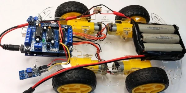
Now the robot is ready. Make a path using 50 mm black tape. The width of black tape should be between 4.8 to 5 cm. Ensure that the tape is not shiny, as shiny surfaces may reflect the sensor light and interfere with accurate detection.
Arduino Line Follower Robot Code
The following sketch is designed to control a line-follower robot using an Arduino and the Adafruit Motor Shield. Upload the code to your Arduino.
/*
Library used: Adafruit Motor Shield library V1 version: 1.0.1
For this code to run as expected:
1.The centre to centre distance between the Line sensors should be 11 to 11.5 cm
2. The width of black tape should be 4.8 to 5 cm
3. The distance of the sensor LED from the flat ground surface should be 2 cm.
*/

#include <AFMotor.h>

// MACROS for Debug print, while calibrating set its value to 1 else keep it 0
#define DEBUG_PRINT 0

// MACROS for Analog Input
#define LEFT_IR A0
#define RIGHT_IR A1

// MACROS to control the Robot
#define DETECT_LIMIT 300
#define FORWARD_SPEED 60
#define TURN_SHARP_SPEED 150
#define TURN_SLIGHT_SPEED 120
#define DELAY_AFTER_TURN 140
#define BEFORE_TURN_DELAY 10

// BO Motor control related data here
// Here motors are running using M3 and M4 of the shield and Left Motor is connected to M3 and Right Motor is connected to M4 using IC2 of the shield
AF_DCMotor motorL(3);  // Uses PWM0B pin of Arduino Pin 5 for Enable
AF_DCMotor motorR(4);  // Uses PWM0A pin of Arduino Pin 6 for Enable

// variables to store the analog values
int left_value;
int right_value;

// Set the last direction to Stop
char lastDirection = 'S';

void setup() {

#if DEBUG_PRINT
  Serial.begin(9600);
#endif

  // Set the current speed of Left Motor to 0
  motorL.setSpeed(0);
  // turn on motor
  motorL.run(RELEASE);
  // Set the current speed of Right Motor to 0
  motorR.setSpeed(0);
  // turn off motor
  motorR.run(RELEASE);

  // To provide starting push to Robot these values are set
  motorR.run(FORWARD);
  motorL.run(FORWARD);
  motorL.setSpeed(255);
  motorR.setSpeed(255);
  delay(40);  // delay of 40 ms
}

void loop() {
  left_value = analogRead(LEFT_IR);
  right_value = analogRead(RIGHT_IR);

#if DEBUG_PRINT
  // This is for debugging. To check the analog inputs the DETECT_LIMIT MACRO value 300 is set by analysing the debug prints
  Serial.print(left_value);
  Serial.print(",");
  Serial.print(right_value);
  Serial.print(",");
  Serial.print(lastDirection);
  Serial.write(10);
#endif

  // Right Sensor detects black line and left does not detect
  if (right_value >= DETECT_LIMIT && !(left_value >= DETECT_LIMIT)) {
    turnRight();
  }
  // Left Sensor detects black line and right does not detect
  else if ((left_value >= DETECT_LIMIT) && !(right_value >= DETECT_LIMIT)) {
    turnLeft();
  }
  // both sensors doesn't detect black line
  else if (!(left_value >= DETECT_LIMIT) && !(right_value >= DETECT_LIMIT)) {
    moveForward();
  }
  // both sensors detect black line
  else if ((left_value >= DETECT_LIMIT) && (right_value >= DETECT_LIMIT)) {
    stop();
  }
}

void moveForward() {
  if (lastDirection != 'F') {
    // To provide starting push to Robot when last direction was not forward
    motorR.run(FORWARD);
    motorL.run(FORWARD);
    motorL.setSpeed(255);
    motorR.setSpeed(255);
    lastDirection = 'F';
    delay(20);
  } else {
    // If the last direction was forward
    motorR.run(FORWARD);
    motorL.run(FORWARD);
    motorL.setSpeed(FORWARD_SPEED);
    motorR.setSpeed(FORWARD_SPEED);
  }
}

void stop() {
  if (lastDirection != 'S') {
    // When stop is detected move further one time to check if its actual stop or not, needed when the robot turns
    motorR.run(FORWARD);
    motorL.run(FORWARD);
    motorL.setSpeed(255);
    motorR.setSpeed(255);
    lastDirection = 'S';
    delay(40);
  } else {
    // When stop is detected next time then stop the Robot
    motorL.setSpeed(0);
    motorR.setSpeed(0);
    motorL.run(RELEASE);
    motorR.run(RELEASE);
    lastDirection = 'S';
  }
}

void turnRight(void) {
  // If first time Right Turn is taken
  if (lastDirection != 'R') {
    lastDirection = 'R';

    // Stop the motor for some time
    motorL.setSpeed(0);
    motorR.setSpeed(0);
    delay(BEFORE_TURN_DELAY);

    // take Slight Right turn
    motorL.run(FORWARD);
    motorR.run(BACKWARD);
    motorL.setSpeed(TURN_SLIGHT_SPEED);
    motorR.setSpeed(TURN_SLIGHT_SPEED);
  } else {
    // take sharp Right turn
    motorL.run(FORWARD);
    motorR.run(BACKWARD);
    motorL.setSpeed(TURN_SHARP_SPEED);
    motorR.setSpeed(TURN_SHARP_SPEED);
  }
  delay(DELAY_AFTER_TURN);
}

void turnLeft() {
  // If first time Left Turn is taken
  if (lastDirection != 'L') {
    lastDirection = 'L';

    // Stop the motor for some time
    motorL.setSpeed(0);
    motorR.setSpeed(0);
    delay(BEFORE_TURN_DELAY);

    // take slight Left turn
    motorR.run(FORWARD);
    motorL.run(BACKWARD);
    motorL.setSpeed(TURN_SLIGHT_SPEED);
    motorR.setSpeed(TURN_SLIGHT_SPEED);
  } else {
    // take sharp Left turn
    motorR.run(FORWARD);
    motorL.run(BACKWARD);
    motorL.setSpeed(TURN_SHARP_SPEED);
    motorR.setSpeed(TURN_SHARP_SPEED);
  }
  delay(DELAY_AFTER_TURN);
}
Code Description
First, we include the AFMotor.h library. It is used to control the motors via the Adafruit Motor Shield.
#include <AFMotor.h>Next, we define macros for analog input and controlling robot:
DEBUG_PRINTis set to 0 initially. You can change this to 1 while calibrating.LEFT_IRandRIGHT_IRrefer to the analog pins (A0 and A1) to which the left and right line sensors are connected.DETECT_LIMITis the threshold value that determines when a sensor detects the black line. If the sensor reading is greater than or equal to 300, it means the black line has been detected.FORWARD_SPEED,TURN_SHARP_SPEED, andTURN_SLIGHT_SPEEDdefine the speed for forward motion, sharp turns, and slight turns, respectively.DELAY_AFTER_TURNandBEFORE_TURN_DELAYare used to control the delay in motor actions before and after turning the robot.
// MACROS to for Debug print, while calibrating set its value to 1 else let it remain 0
#define DEBUG_PRINT 0

// MACROS for Analog Input
#define LEFT_IR A0
#define RIGHT_IR A1

// MACROS to control the Robot
#define DETECT_LIMIT 300
#define FORWARD_SPEED 60
#define TURN_SHARP_SPEED 150
#define TURN_SLIGHT_SPEED 120
#define DELAY_AFTER_TURN 140
#define BEFORE_TURN_DELAY 10
Now, we initialise the motors. The left motor is connected to output M3, and the right motor is connected to output M4.
// BO Motor control related data here
// Here motors are running using M3 and M4 of the shield and Left Motor is connected to M3 and Right Motor is connected to M4 using IC2 of the shield
AF_DCMotor motorL(3);  // Uses PWM0B pin of Arduino Pin 5 for Enable
AF_DCMotor motorR(4);  // Uses PWM0A pin of Arduino Pin 6 for Enable
We define a few global variables here:
left_valueandright_valueare used to store the sensor readings from the left and right Line sensors.lastDirectionkeeps track of the robot’s last movement. Initially, it is set to ‘S’, meaning the robot is stopped.
// variables to store the Analog Values
int left_value;
int right_value;
// Set the Last Direction to Stop
char lastDirection = 'S';
In the setup function, we initialize the serial communication if debugging is enabled (DEBUG_PRINT set to 1).
Next, we set both motors to a speed of 0 and stop them using RELEASE, which cuts power to the motors.
After that, we give the motors an initial “push” by setting them to full speed (255) in the forward direction. This helps the robot get moving right at the start.
void setup() {

#if DEBUG_PRINT
  Serial.begin(9600);
#endif

  // Set the current speed of left Motor to 0
  motorL.setSpeed(0);
  // turn on motor
  motorL.run(RELEASE);
  // Set the current speed of Right Motor to 0
  motorR.setSpeed(0);
  // turn off motor
  motorR.run(RELEASE);

  // To provide starting push to Robot these values are set
  motorR.run(FORWARD);
  motorL.run(FORWARD);
  motorL.setSpeed(255);
  motorR.setSpeed(255);
  delay(40);  // delay of 40 ms
}
In the loop function, we continuously read the values from the left and right Line sensors using analogRead.
- If debugging is enabled, we print these values to the serial monitor for analysis.
Next, we check the sensor values and determine the robot’s movement based on which sensor detects the black line:
- If the right sensor detects the black line but the left sensor doesn’t, the robot will turn right.
- If the left sensor detects the black line but the right sensor doesn’t, it will turn left.
- If neither sensor detects the line, the robot moves forward.
- If both sensors detect the black line, the robot stops.
void loop() {
  left_value = analogRead(LEFT_IR);
  right_value = analogRead(RIGHT_IR);

#if DEBUG_PRINT
  // This is for debugging. To check the analog inputs the DETECT_LIMIT MACRO value 300 is set by analysing the debug prints
  Serial.print(left_value);
  Serial.print(",");
  Serial.print(right_value);
  Serial.print(",");
  Serial.print(lastDirection);
  Serial.write(10);
#endif

  // Right Sensor detects black line and left does not detect
  if (right_value >= DETECT_LIMIT && !(left_value >= DETECT_LIMIT)) {
    turnRight();
  }
  // Left Sensor detects black line and right does not detect
  else if ((left_value >= DETECT_LIMIT) && !(right_value >= DETECT_LIMIT)) {
    turnLeft();
  }
  // both sensors doesn't detect black line
  else if (!(left_value >= DETECT_LIMIT) && !(right_value >= DETECT_LIMIT)) {
    moveForward();
  }
  // both sensors detect black line
  else if ((left_value >= DETECT_LIMIT) && (right_value >= DETECT_LIMIT)) {
    stop();
  }
}
Moves Forward
If the last movement was not forward, the robot will briefly run at full speed to start moving forward. Otherwise, it runs at the defined FORWARD_SPEED.
void moveForward() {
  if (lastDirection != 'F') {
    // To provide starting push to Robot when last direction was not forward
    motorR.run(FORWARD);
    motorL.run(FORWARD);
    motorL.setSpeed(255);
    motorR.setSpeed(255);
    lastDirection = 'F';
    delay(20);
  } else {
    // If the last direction was forward
    motorR.run(FORWARD);
    motorL.run(FORWARD);
    motorL.setSpeed(FORWARD_SPEED);
    motorR.setSpeed(FORWARD_SPEED);
  }
}
Stop
When both sensors detect the black line, the robot briefly moves forward to confirm the stop. If it detects the stop condition again, the robot stops completely.
void stop() {
  if (lastDirection != 'S') {
    // When stop is detected move further one time to check if its actual stop or not, needed when the robot turns
    motorR.run(FORWARD);
    motorL.run(FORWARD);
    motorL.setSpeed(255);
    motorR.setSpeed(255);
    lastDirection = 'S';
    delay(40);
  } else {
    // When stop is detected next time then stop the Robot
    motorL.setSpeed(0);
    motorR.setSpeed(0);
    motorL.run(RELEASE);
    motorR.run(RELEASE);
    lastDirection = 'S';
  }
}
Turns Right
If the robot turns right for the first time, it briefly stops, takes a slight turn, and then continues with a sharper turn if required.
void turnRight(void) {
  // If First time Right Turn is Taken
  if (lastDirection != 'R') {
    lastDirection = 'R';

    // Stop the motor for some time
    motorL.setSpeed(0);
    motorR.setSpeed(0);
    delay(BEFORE_TURN_DELAY);

    // take Slight Right turn
    motorL.run(FORWARD);
    motorR.run(BACKWARD);
    motorL.setSpeed(TURN_SLIGHT_SPEED);
    motorR.setSpeed(TURN_SLIGHT_SPEED);
  } else {
    // take sharp Right turn
    motorL.run(FORWARD);
    motorR.run(BACKWARD);
    motorL.setSpeed(TURN_SHARP_SPEED);
    motorR.setSpeed(TURN_SHARP_SPEED);
  }
  delay(DELAY_AFTER_TURN);
}
Turns Left
The turnLeft() function controls a robot’s left turn. It checks if the robot is turning left for the first time by comparing the variable lastDirection.
If it’s the first left turn, the robot stops both motors briefly, then takes a slight left by moving the right motor forward and the left motor backward at a low speed.
If the robot has already turned left before, it skips the stop and takes a sharp left by running the motors at higher speed. Finally, a delay (DELAY_AFTER_TURN) is added to allow the turn to complete before further movement.
void turnLeft() {
  // If First time Left Turn is Taken
  if (lastDirection != 'L') {
    lastDirection = 'L';

    // Stop the motor for some time
    motorL.setSpeed(0);
    motorR.setSpeed(0);
    delay(BEFORE_TURN_DELAY);

    // take slight Left turn
    motorR.run(FORWARD);
    motorL.run(BACKWARD);
    motorL.setSpeed(TURN_SLIGHT_SPEED);
    motorR.setSpeed(TURN_SLIGHT_SPEED);
  } else {
    // take sharp Left turn
    motorR.run(FORWARD);
    motorL.run(BACKWARD);
    motorL.setSpeed(TURN_SHARP_SPEED);
    motorR.setSpeed(TURN_SHARP_SPEED);
  }
  delay(DELAY_AFTER_TURN);
}
How to calibrate line follower Robot?
-
In the code set MACRO to 1 and upload the code into Arduino, make sure that the PWR pin jumper is disconnected.
-
While the cable is connected to Arduino, put the Robot on the black line and make sure the black line is exactly between the sensors.
-
Open the terminal and check the prints on serial monitor window.
-
The first value is the analog output of the left sensor and the value after the comma is the Analog output of the right sensor.
-
Now put the left sensor on the black line, and you will notice the first value increases, similarly put the Right sensor on the black line, and you will notice the second value increases.
-
The minimum value you get when the sensor is just over the black line is the value of MACRO DETECT_LIMIT in code. This value is the same for the left and the right sensor. Just update the value in the code for your robot and upload the code in Arduino.
-
Remove the cable from Arduino. Connect the 12 V power supply to Arduino, place the PWR jumper, and run your autonomous line follower robot.
Troubleshooting
Issue 1: Robot veers off course or fails to follow the line consistently.
Solution: Check the alignment of the sensor module and adjust its position if necessary. Also, ensure that the motors are functioning correctly and that the wheels are properly attached to the chassis.
Issue 2: Sensor readings are erratic or unreliable.
Solution: Clean the sensor modules and the surface on which the robot is operating to remove any dirt or debris that may be interfering with the sensor readings. Additionally, check the wiring connections for any loose or damaged wires.
Issue 3: Motors are not responding to the Arduino commands.
Solution: Double-check the wiring connections between the Arduino, motor driver module, and motors. Make sure that the motor driver module is receiving power and that the Arduino is sending the correct signals to control the motors.

