
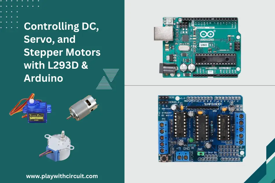
The L293D Motor Driver Shield is one of the most versatile shields for driving DC, stepper and servo motors with an Arduino. This full-featured shield can control up to 4 DC motors, two steppers and two 5V servos.
In this tutorial, we will learn about how to use an L293D motor driver shield with Arduino to control the speed and direction of rotation of these motors.
What is L293D Motor Driver Shield?
The L293D motor driver shield acts as an interface between the Arduino and the motors, providing bidirectional control for up to four DC motor or two stepper motors and two Servo Motors simultaneously. The shield is equipped with the L293D IC, which contains two H-bridge circuits capable of driving motors with voltages up to 36V and currents up to 600mA per channel.
L293D shield simplifies motor control tasks by offering simple connections and control pins for controlling direction and speed. It can be easily integrated into their projects to power various motor-driven mechanisms such as robots, vehicles, and automated systems.
L293D Motor Driver Shield Features
- Two servo motors connections.
- It can drive up to four bidirectional DC motors.
- It can drive up to two unipolar or bipolar stepper motors.
- Offers bidirectional control for easy motor direction changes.
- Pull-down resistors disable motors during power-up.
- For separate logic/motor supplies, a 2-pin terminal block and a jumper are used to connect external power.
- 5V compatible on logic pins.
L293D Motor Driver Shield Hardware Overview
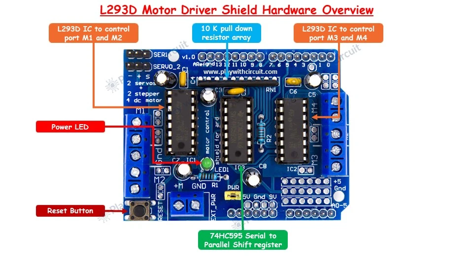
L293D IC L293D IC is the heart of the motor driver shield. It is a 16-pin IC with eight pins on each side for controlling the motor. A single IC is able to control two DC motors or one stepper motor. The motor driver shield has two L293D ICs, so it can control four DC motors or two stepper motors. One L293D IC controls port M1 and M2 and another controls ports M3 and M4.
74HC595 Shift Register The 74HC595 shift register is an 8-bit serial input and serial output shift register. It is used to extend the number of direction control pins of the L293D motor driver ICs. The eight parallel outputs of this shift register IC are connected to the input pins 2, 7, 10 and 15 of both L293D IC.
Reset Button To reset Arduino UNO, this is the same rest button which is available at Arduino UNO. It is just brought on the shield to make access easier.
Power LED It indicates that power supply for motors is available.
Resistor Array A 10k pull down network resistor is added to pull down the motor pin, when the board is powered up.
L293D Motor Driver Pinout
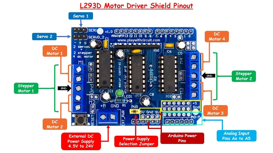
DC Motor Connections
- The shield features two L293D ICs, each with two output channels. These channels are accessible through four terminals labelled M1, M2, M3, and M4. There is ground connection between M1-M2 and M3-M4 connectors.
- You can connect up to four DC motors operating at voltages between 4.5V and 24V to these terminals.
- Each channel can supply up to 600 mA of continuous current (with a peak of 1.2A), depending on the capacity of the motor power supply.
Stepper Motor Connections
- The shield provides the connection for two stepper motors.
- One stepper motor can be connected to terminals M1-M2, and the other can be connected to terminals M3-M4.
Servo Motor Connections
- The shield provides 16-bit PWM output lines accessible via two 3-pin headers. A single servo motor comes with three wires so it allows the connection of two servo motors which can be connected at port Servo 1 and Servo 2. Servo 1 can be controlled using PWM pin 10 and Servo 2 can be controlled using PWM pin 9 of the Arduino.
- Servo motors are powered directly from the Arduino’s 5V supply, which can lead to issues such as overheating of the Arduino’s onboard 5V regulator thus the shield has a 100uF capacitor on the power pins of the servo headers to mitigate these issues. It is advisable to check the power ratings of the servo motor before connecting it with a shield.
Power Supply and Jumper Connections
The shield is compatible with motor voltages ranging from 4.5 to 24 volts. We can power the motors and shield in different ways. A power selection jumper (PWR) is provided near the power connector allowing you to choose between different ways to power the motor and shield.
Single Power Supply for Motors and Shield: If you’re using motors that operate within a 12V range, you can use a single DC power supply for both the motor driver and the Arduino. You can power the driver shield through the Arduino’s DC Jack. This method simplifies wiring by requiring only one power supply. Make sure that the power selection jumper is placed on the shield.
Separate Power Supplies for Motors and Shield: You can also use separate power supplies for the motors and the shield. First remove the jumper then power the Arduino through its USB and the shield through an external DC power supply connected to the two-terminal power connector labelled “EXT_PWR.” Make sure that the power selection jumper is not placed on the shield.
Warning
When using the external power supply terminals on the shield, it’s important to ensure that the power selection jumper is removed from the shield. Leaving the jumper in place can cause a short circuit between the two power supplies that could damage both the motor shield and the Arduino board.
Arduino Power Pins
Arduino 5V, GND and Vin pins are given for easy access. In above pic the pin labelled 9V is actually Vin pin. Whatever voltage is applied at power jack of Arduino, it is available at this Pin and when the power Jumper is connected, this Vin pin is connected to the Power supply pin of Motor on L293D IC.
Analog Input Pins
Analog Input Pins A0 to A5 is given for connecting with Arduino for easy access.
How many Arduino UNO pins are used by L293D Motor Driver Shield?
Pin D3, D4, D5, D6, D7, D8, D9, D10, D11, and D12 are used by the Shield.
Here is the schematic of L293D Motor Driver Shield:
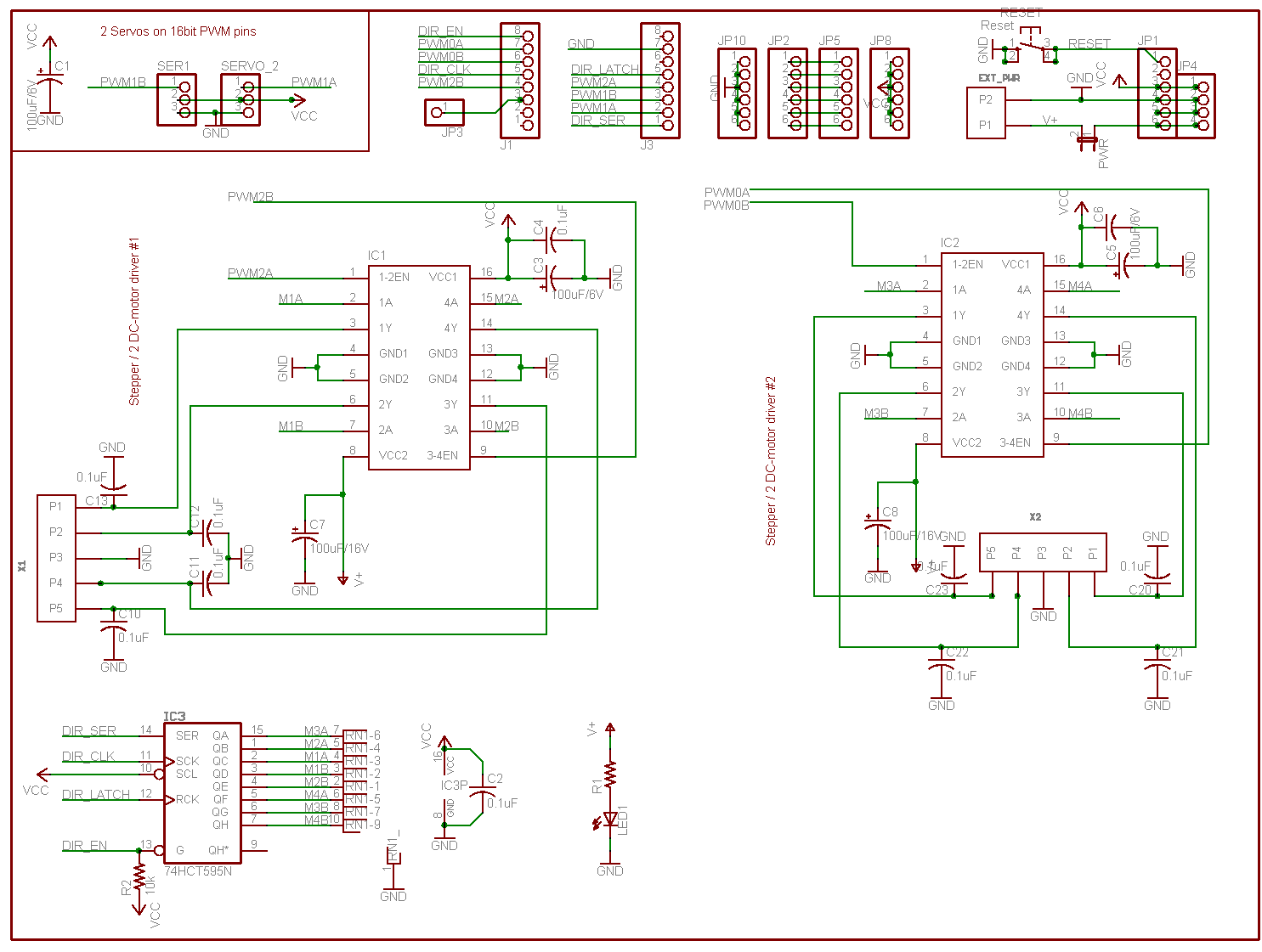
Let us correlate above schematic with the pins on the shield.
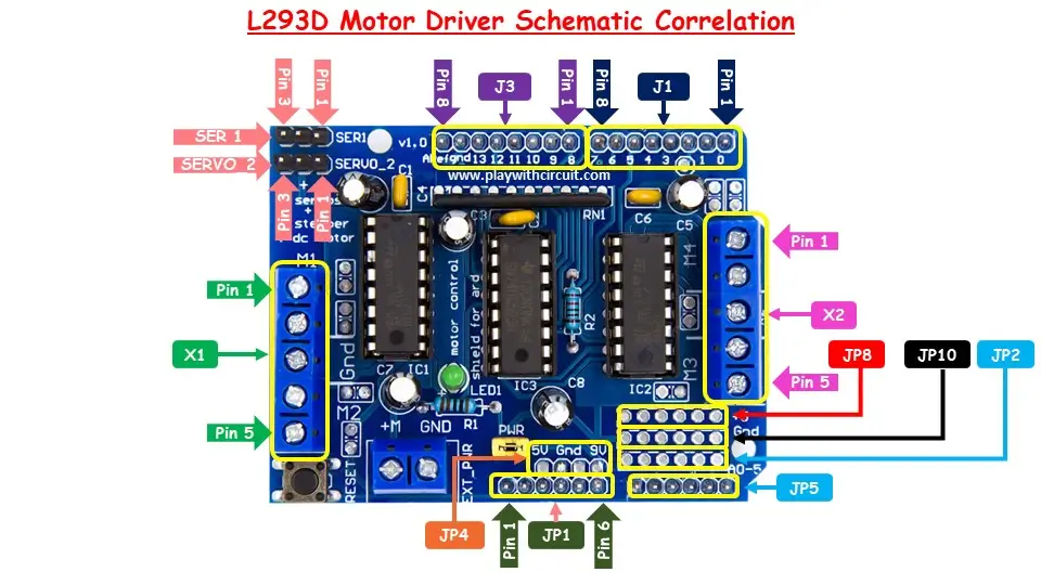
Connector J1
| Pin No. of Connector | Pin Name | Arduino Pin | Functionality |
|---|---|---|---|
| 1 | Not Used | D0 | Not Used |
| 2 | Not Used | D1 | Not Used |
| 3 | Not Used | D2 | Not Used |
| 4 | PWM2B | D3 | Enable pin of L293D IC controlling port M2 |
| 5 | DIR_CLK | D4 | Clock Pin of 74HC595 |
| 6 | PWM0B | D5 | Enable Pin of L293D IC controlling port M3 |
| 7 | PWM0A | D6 | Enable Pin of L293D IC controlling port M4 |
| 8 | DIR_EN | D7 | Enable Pin of 74HC595 |
Connector J3
| Pin No. of Connector | Pin Name | Arduino Pin | Functionality |
|---|---|---|---|
| 1 | DIR_SER | D8 | Serial Data Input Pin of 74HC595 |
| 2 | PWM1A | D9 | PWM control pin of Second Servo Port(SERVO_2) |
| 3 | PWM1B | D10 | PWM control pin of First Servo Port(SER1) |
| 4 | PWM2A | D11 | Enable pin of L293D IC controlling port M1 |
| 5 | DIR_LATCH | D12 | Latch Pin of 74HC595 |
| 6 | Not Used | D13 | Not Used |
| 7 | Gnd | Gnd | Ground |
| 8 | Not Used | Aref | Not Used |
Connector JP1
| Pin No. of Connector | Arduino Pin |
|---|---|
| 1 | Reset Pin |
| 2 | 3.3V pin |
| 3 | 5V pin |
| 4 | GND |
| 5 | GND |
| 6 | Vin Pin |
Normally we should not use the pins which are used to run the shield. If we have to use those pins then we have to judiciously use the pins e.g., if we are using only M1 and M2 port of the shield then we can use other pins of Arduino connected to port M3 and M4 and SER1 and SERVO_2.
If we are using any DC motor port weather M1, M2, M3 or M4 we can’t use pins D4, D7, D8 and D12 as it is used by 74HC595 serial shift register IC.
Controlling DC Motor with Arduino UNO and L293D Motor Driver Shield
Let’s learn how to control 5V DC motors using Arduino and L293D shield. We will be controlling the direction of rotation and speed of the Motor.
Hardware and Software Requirements
Hardware Required
| Component Name | Quantity | Remarks | Where to Buy |
|---|---|---|---|
| Arduino UNO | 1 | Revision R3 | Amazon.com / Amazon.in / Banggood |
| L293D Motor Driver Shield | 1 | For driving DC motor | Amazon.com / Amazon.in |
| DC motor | 1 | 5V | Amazon.com / Amazon.in |
| Push button | 3 | to rotate and stop the motor | Amazon.com / Amazon.in / Banggood |
| POT | 1 | 10Kohm, for changing the speed of the Motor | Amazon.com / Amazon.in / Banggood |
| LCD 16x2 | 1 | I2C type, for displaying speed and direction | Amazon.com / Amazon.in |
| 12V Supply Adapter | 1 | For providing power to Arduino | Amazon.com / Amazon.in / Banggood |
| 5V Supply Adapter | 1 | For providing external power supply to driver module | Amazon.com / Amazon.in |
| Breadboard | 1 | Full size | Amazon.com / Amazon.in / Banggood |
| Jumper Wires | 20 | For Motor, driver, LCD and Arduino connections | Amazon.com / Amazon.in / Banggood |
| USB Cable Type A to B | 1 | for programming Arduino UNO | Amazon.com / Amazon.in |
Software Required
- Arduino IDE, Version 2.1.1 or above installed on your PC
- Adafruit Motor Shield Library(V1) by Adafruit version 1.0.1.
- LiquidCrystal I2C Library by Frank de Barbander 1.1.2
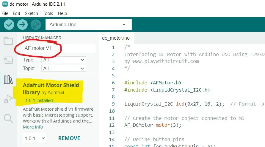
Installing AFMotor Library
To communicate with the shield, the first step is to install the AFMotor.h library. This library enables us to control DC, stepper, and servo motors using straightforward commands.
To install the AFMotor library, you can follow these steps:
- Open Arduino IDE.
- Navigate to Sketch > Include Library > Manage Libraries (or press ctrl + shift + I).
- In the search bar, enter AF motor V1.
- Look for Adafruit Motor Shield library (V1 Firmware) by Adafruit.
- Click on it and choose Install.
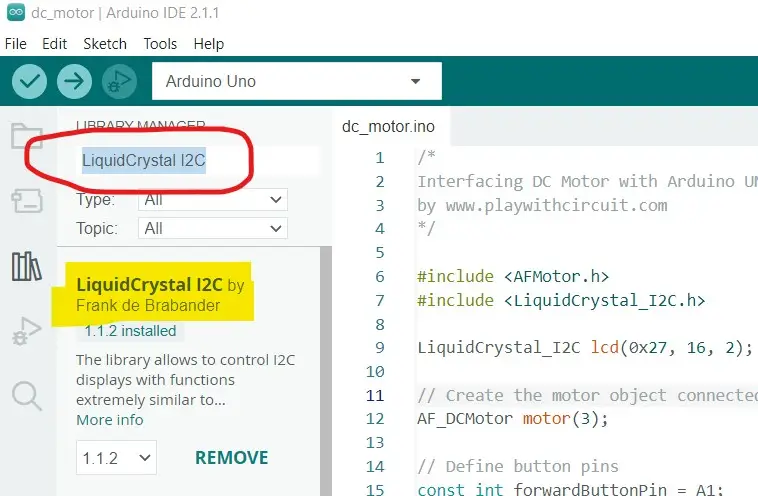
Installing LCD Library
To communicate with the LCD, we need to install the LiquidCrystal library. Here are the steps to install the LiquidCrystal library:
- Open Arduino IDE.
- Navigate to Sketch > Include Library > Manage Libraries (or press ctrl + shift + I).
- In Library Manager enter LiquidCrystal I2C into the search bar.
- Click on the library, and choose Install.
Commonly Used Functions of AFMotor Library for running DC motor
AF_DCMotor Class
Creates an instance of the AF_DCMotor class, representing a DC motor connected to the motor shield.
Syntax
AF_DCMotor motorname(portnum);Parameters
- portnum: It can be 1, 2, 3 or 4 based on port (M1, M2, M3 and M4 respectively) on which DC motor is connected.
setSpeed()
The setSpeed() function sets the speed of the motor.
Syntax
motorname.setSpeed(speedValue);Parameters
- speedValue: A value ranging from 0 (stopped) to 255 (maximum speed).
run()
Controls the direction and state of the motor.
Syntax
motorname.run(cmd)Parameters
- cmd: The command to control the motor, which can be FORWARD, BACKWARD, or RELEASE.
Wiring of DC motor with L293D shield and Arduino UNO
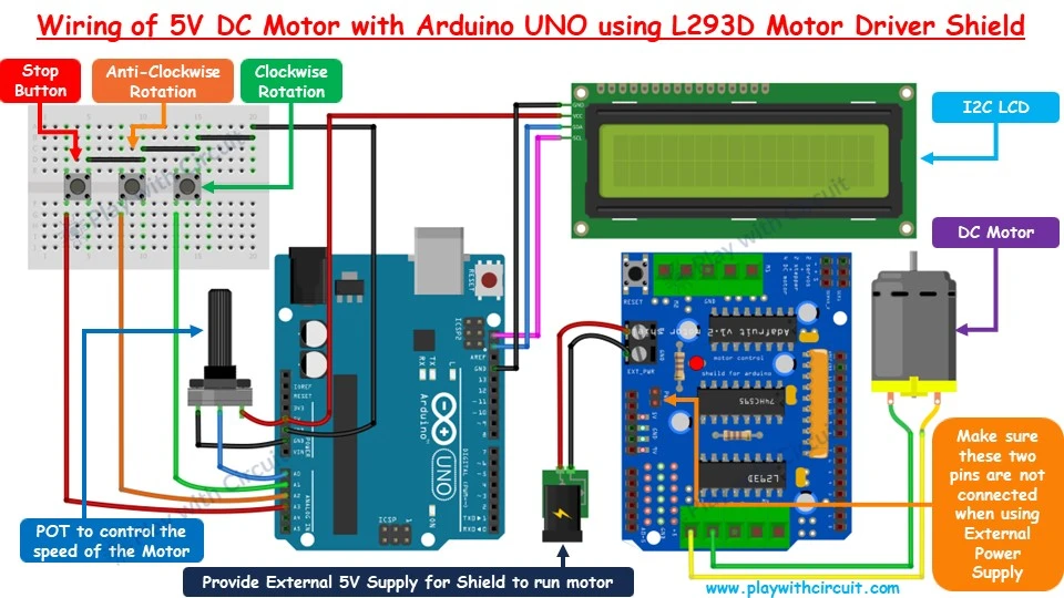
In the above wiring diagram, the L293D Shield shown beside the Arduino should be mounted on the Arduino. It is shown like this for simplicity and for showing button and POT connections.
Pin A0 is the Analog input pin connected with the POT’s middle pin. The other two POT pins are connected to the Arduino’s VCC and GND pins. This POT changes the voltage on the A0 pin. According to the voltage on the A0 pin the speed of the motor changes higher the voltage higher the speed.
As pin numbers D3, D4, D5, D6, D7, D8, D9, D10, D11, and D12 are used by the Shield and D0 and D1 are the Serial pins. D13 is connected to the on-board LED. There is only 1 digital pin left i.e., D2. Hence in this article, we are using Analog Input pins of Arduino as digital input pins.
Hence for the button connections A1, A2, and A3 pins are used. The button connected to the A1 pin is responsible for clockwise rotation, A2 is for Anti-clockwise rotation and A3 is to stop the motor.
The 16×2 LCD is connected to the I2C pins of Arduino UNO to display speed and direction of rotation of motor. 5V DC motor is connected at port M3 of the shield. External 5V DC supply is provided at the EXT_PWR pin of the Shield via DC Jack.
❕Note
Make sure that the Jumper is not connected to the PWR pins of the shield.
The connections are shown in the following table:
| Arduino Pin | Connected to |
|---|---|
| 5V | Vcc pin of LCD and pin 1 of POT |
| Gnd | Gnd pin of LCD and pin 3 of POT |
| A0 | pin 2 of POT |
| A1 | Clockwise rotation Button |
| A2 | Anti-Clockwise rotation Button |
| A3 | Stop Button |
| SCL | SCL pin of LCD |
| SDA | SDA pin of LCD |
Arduino Code
This following code will show you how to control a DC motor using the L293D motor driver shield. The motor’s direction and speed are controlled using three buttons (for forward, reverse, and stop) and a potentiometer to adjust the speed. LCD is used to display the motor’s direction and speed.
Code
/*
Interfacing DC Motor with Arduino UNO using L293D motor Driver shield
by www.playwithcircuit.com
*/

#include <AFMotor.h>
  // Library to run DC Motor Using Motor Driver Shield
#include <LiquidCrystal_I2C.h>
  // Library to Run I2C LCD

LiquidCrystal_I2C lcd(0x27, 16, 2);  // Format -> (Address,Columns,Rows )

// Create the motor object connected to M3
AF_DCMotor motor(3);

// Define button pins
const int forwardButtonPin = A1;
const int reverseButtonPin = A2;
const int stopButtonPin    = A3;

// Define potentiometer pin
const int potPin = A0;

// Variables to store motor state and direction
bool motorRunning  = false;
int motorDirection = BACKWARD;  // FORWARD or BACKWARD

// Read the potentiometer value
int potValue;
int motorSpeed;

// Variable to store button states
bool forwardButtonState;
bool stopButtonState;
bool reverseButtonState;

// Inline function to check if button is pressed packed with debouncing logic
inline bool chkButtonState(int pinNum, int checkState, int debounceDelay) {
  if (((digitalRead(pinNum) == checkState) ? true : false) == true) {
    delay(debounceDelay);
    return (((digitalRead(pinNum) == checkState) ? (true) : (false)) == true);
  } else {
    return false;
  }
}

void setup() {
  // initialize the lcd
  lcd.init();
  // Turn on the Backlight
  lcd.backlight();
  // Clear the display buffer
  lcd.clear();

  // Set cursor (Column, Row)
  lcd.setCursor(0, 0);
  lcd.print("DC Motor using");
  lcd.setCursor(0, 1);
  lcd.print("L293D Shield");

  // Set button pins as inputs
  pinMode(forwardButtonPin, INPUT_PULLUP);
  pinMode(stopButtonPin   , INPUT_PULLUP);
  pinMode(reverseButtonPin, INPUT_PULLUP);

  // Start with motor off
  motor.setSpeed(0);
  motor.run(RELEASE);

  delay(2000);

  // Clear the display buffer
  lcd.clear();
  // Set cursor (Column, Row)
  lcd.setCursor(0, 0);
  lcd.print("Motor Direction:");
  lcd.setCursor(0, 1);
  lcd.print("Stopped   ");
}

void loop() {
  // Read the potentiometer value for changing speed as per Analog input
  potValue   = analogRead(potPin);
  motorSpeed = map(potValue, 0, 1023, 0, 255);

  // Read the button states
  forwardButtonState = chkButtonState(forwardButtonPin, LOW, 20);
  reverseButtonState = chkButtonState(reverseButtonPin, LOW, 20);
  stopButtonState    = chkButtonState(stopButtonPin,    LOW, 20);

  // check for Forward run
  if (forwardButtonState && (!motorRunning || motorDirection == BACKWARD)) {
    // Set cursor (Column, Row)
    lcd.setCursor(0, 1);
    lcd.print("Clock   ");
    if (motorDirection == BACKWARD) {
      motor.setSpeed(0);
      motor.run(RELEASE);
      delay(1000);
    }
    motorRunning = true;
    motorDirection = FORWARD;
    motor.setSpeed(motorSpeed);
    motor.run(FORWARD);
  }

  // check for Reverse run
  else if (reverseButtonState && (!motorRunning || motorDirection == FORWARD)) {
    // Set cursor (Column, Row)
    lcd.setCursor(0, 1);
    lcd.print("Anti-Clk");
    if (motorDirection == FORWARD) {
      motor.setSpeed(0);
      motor.run(RELEASE);
      delay(1000);
    }
    motorRunning = true;
    motorDirection = BACKWARD;
    motor.setSpeed(motorSpeed);
    motor.run(BACKWARD);
  }

  // Stop motor
  else if (stopButtonState && motorRunning) {
    // Set cursor (Column, Row)
    lcd.setCursor(0, 1);
    lcd.print("Stopped         ");
    motorRunning = false;
    motor.setSpeed(0);
    motor.run(RELEASE);
  }

  // Adjust motor speed if running and display speed on LCD
  if (motorRunning) {
    motor.setSpeed(motorSpeed);
    // Set cursor (Column, Row)
    lcd.setCursor(9, 1);
    lcd.print("SPD:");
    lcd.print(((motorSpeed*100)/255));
    lcd.print("%  ");
  }
}
Code Explanation
Firstly we include AFMotor library and LCD library.
Then we create an LCD object with the I2C address 0x27, and it is configured for 16 columns and 2 rows.
Then we create a motor object AF_DCMotor and assign it to port M3 on the motor shield.
Next we define Pins and Variables:
- Button Pins: We define three analog pins (A1, A2, A3) for the forward, reverse, and stop buttons.
- Potentiometer Pin: We define an analog pin (A0) for the potentiometer.
- Motor State Variables: We define variables to keep track of whether the motor is running (motorRunning), the direction of the motor (motorDirection), and to store the potentiometer value and the motor speed.
- Button State Variables: Variables are defined to store the current state of each button (pressed or not).
Then we use chkButtonState function to check the state of a button with debouncing logic. This ensures that the button press is stable and not affected by mechanical noise. The function reads the button state, adds a delay for debouncing, and reads the state again to confirm the button press.
In the Setup function, we initialize the LCD, configure the button pins as inputs with internal pull-up resistors and initialize the motor.
In the Loop function,
- We read the potentiometer value and map it to a range of 0-255 for motor speed. Then we read the states of the forward, reverse, and stop buttons with debouncing.
- If the forward button is pressed and the motor is either not running or running backward, the motor will start running forward. The LCD displays “Clock” (for Clockwise).
- If the reverse button is pressed and the motor is either not running or running forward, the motor will start running backward. The LCD displays “Anti-Clk” (for Anti-Clockwise).
- If the stop button is pressed and the motor is running, the motor stops. The LCD displays “Stopped”.
- Adjusting Motor Speed: If the motor is running, the speed is continuously adjusted based on the potentiometer value. The speed percentage is calculated and displayed on the LCD.
💡Must Read
DC Motor Control with Arduino
This article will give you more in-depth information about DC Motor, its working and interfacing it with Arduino using L293D IC.
Controlling Micro Servo Motor with Arduino UNO and L293D Motor Driver Shield
Let’s learn how to control 5V Micro Servo Motor SG90 using Arduino and L293D shield. We will be controlling the direction of the Arm of the Servo Motor and the speed of the Motor.
Hardware and Software Requirements
Hardware Required
| Component Name | Quantity | Remarks | Where to Buy |
|---|---|---|---|
| Arduino UNO | 1 | Revision R3 | Amazon.com / Amazon.in / Banggood |
| L293D Motor Driver Shield | 1 | For driving DC motor | Amazon.com / Amazon.in |
| Servo Motor | 1 | SG90, 5V | Amazon.com / Amazon.in |
| Push button | 2 | to rotate the motor | Amazon.com / Amazon.in / Banggood |
| POT | 1 | 10Kohm, for changing the speed of the Motor | Amazon.com / Amazon.in / Banggood |
| LCD 16x2 | 1 | I2C type, for displaying speed and direction | Amazon.com / Amazon.in |
| 12V Supply Adapter | 1 | For providing power to Arduino | Amazon.com / Amazon.in / Banggood |
| 5V Supply Adapter | 1 | For providing external power supply to driver module | Amazon.com / Amazon.in |
| Jumper Wires | 20 | For Motor, driver, LCD and Arduino connections | Amazon.com / Amazon.in / Banggood |
| Breadboard | 1 | Full size | Amazon.com / Amazon.in / Banggood |
| USB Cable Type A to B | 1 | for programming Arduino UNO | Amazon.com / Amazon.in |
Software Required
- Arduino IDE, Version 2.1.1 or above installed on your PC
- Servo library by Arduino (inbuilt Library).
- LiquidCrystal I2C Library by Frank de Barbander 1.1.2
Wiring of Servo Motor with L293D shield and Arduino UNO
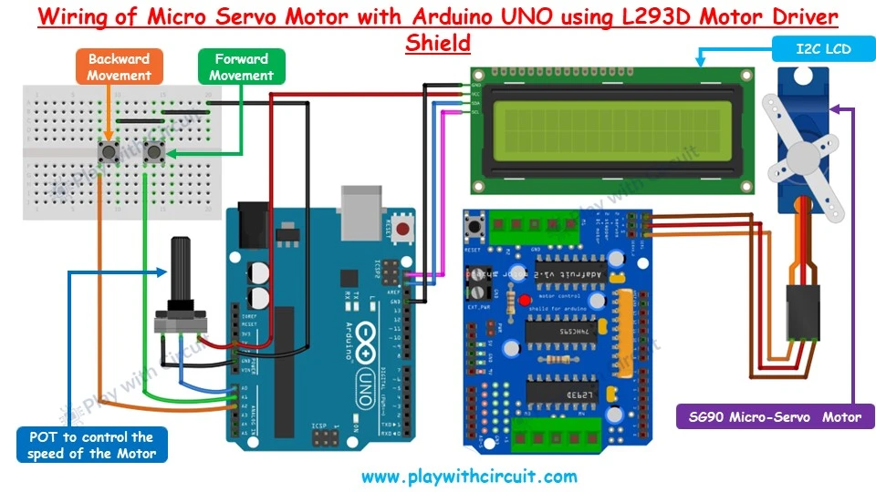
In the above wiring diagram, the Shield shown beside the Arduino should be mounted on the Arduino. It is shown like this for simplicity and for showing button and POT connections.
Pin A0 is the Analog input pin connected with the POT’s middle pin.
The other two POT pins are connected to the Arduino’s VCC and GND pin.
This POT changes the voltage on the A0 pin. According to the voltage on the A0 pin the speed of the motor changes higher the voltage higher the speed.
We are using Analog Input pins of Arduino as digital input pins.
Hence for the button connections A1 and A2 pins are used. The button connected to the A1 pin is responsible for moving Arm in the forward direction (from left to right) and the button connected to the A2 pin is responsible for moving Arm in the backward direction (from right to left). As long as the button is pressed the arm moves. When the circuit is powered up, the arm moves to the centre.
The 16×2 LCD is connected to the I2C pins of Arduino UNO to display speed and motor direction.
5V SG 90 Servo Motor is connected at port SER1 of the shield. It will get power from the Arduino’s 5V pin and its control (orange wire) pin is connected to PWM pin 10 of Arduino.
The connections are shown in the following table:
| Arduino Pin | Connected to |
|---|---|
| 5V | Vcc pin of LCD and pin 1 of POT |
| Gnd | Gnd pin of LCD and pin 3 of POT |
| A0 | pin 2 of POT |
| A1 | Forward Movement Button |
| A2 | Backward Movement Button |
| SCL | SCL pin of LCD |
| SDA | SDA pin of LCD |
Arduino Code
The following Arduino sketch will show you how to control a Micro Servo Motor SG90 using an L293D Motor Driver Shield and displays the motor’s status on an I2C LCD.
The motor’s direction is controlled using two buttons (for forward and reverse), and the speed is adjusted using a potentiometer.
Code
/*
Interfacing Micro Servo Motor SG90 with Arduino UNO using L293D motor Driver shield
by www.playwithcircuit.com
*/
#include <Servo.h>
  // Library to run Servo Motor
#include <LiquidCrystal_I2C.h>
  // Library to Run I2C LCD

LiquidCrystal_I2C lcd(0x27, 16, 2);  // Format -> (Address,Columns,Rows )

// Create the servo object connected to SER1
Servo servo;

// Define button pins
const int forwardButtonPin = A1;
const int reverseButtonPin = A2;

// Variable so save current Servo Angle
int servoAngle;

// Define potentiometer pin
const int potPin = A0;

// Read the potentiometer value
int potValue;
// Save motor Speed
int motorSpeed;
// Save previous motor Speed
int previousSpeed;
// counter to clear speed when motor is stopped
int counter = 100;;

void setup() {
  // initialize the lcd
  lcd.init();
  // Turn on the Backlight
  lcd.backlight();
  // Clear the display buffer
  lcd.clear();

  // Set cursor (Column, Row)
  lcd.setCursor(0, 0);
  lcd.print("Servo Motor using");
  lcd.setCursor(0, 1);
  lcd.print("L293D Shield");

  // Set the arm in middle i.e at 90 degree
  servoAngle = 90;

  // Set button pins as inputs
  pinMode(forwardButtonPin, INPUT_PULLUP);
  pinMode(reverseButtonPin, INPUT_PULLUP);

  // Initialize the servo motor, Pin 10 is connected to the PWM pin of Ser1 port of Arduino Shield
  servo.attach(10);
  servo.write(servoAngle); // Set servo to neutral position (90 degrees)

  delay(2000);

  // Clear the display buffer
  lcd.clear();
  // Set cursor (Column, Row)
  lcd.setCursor(0, 0);
  lcd.print("Motor Direction:");
  lcd.setCursor(0, 1);
  lcd.print("Stopped ");
}

void displaySpeed(void){
    // Set cursor (Column, Row)
    lcd.setCursor(9, 1);
    lcd.print("SPD:");
    lcd.print(((motorSpeed*100)/10));
    lcd.print("%  ");
    counter = 0;
}

void loop() {
  // Read the potentiometer value for changing speed as per Analog input
  potValue   = analogRead(potPin);
  motorSpeed = map(potValue, 0, 1023, 0, 10);

  // Read the button states
  bool forwardButtonState = (digitalRead(forwardButtonPin) == LOW);
  bool reverseButtonState = (digitalRead(reverseButtonPin) == LOW);

  // Control the servo motor
  if (forwardButtonState) {
    // Set cursor (Column, Row)
    lcd.setCursor(0, 1);
    lcd.print("Forward ");
    // Increase Servo Angle
    servoAngle+=motorSpeed;
    if(servoAngle>180)
    {
      servoAngle = 180;
    }
    displaySpeed();
  } else if (reverseButtonState) {
    // Set cursor (Column, Row)
    lcd.setCursor(0, 1);
    lcd.print("Backward");
    // Decrease Servo Angle
    servoAngle-=motorSpeed;
    if(servoAngle<0)
    {
      servoAngle = 0;
    }
    displaySpeed();
  }
  else
  {
    if(counter++ > 100)
    {
      lcd.setCursor(0, 1);
      lcd.print("Stopped         ");
      counter = 101;
    }
    else
    {
      // Set cursor (Column, Row)
      lcd.setCursor(0, 1);
      lcd.print("Stopped ");
    }

    if(previousSpeed != motorSpeed)
    {
      displaySpeed();
      previousSpeed = motorSpeed;
    }
  }
  servo.write(servoAngle); // Adjust as needed for your servo's forward position
}
Code Explanation
The sketch begins by including two Libraries
- Servo.h for controlling the servo motor.
- LiquidCrystal_I2C.h for controlling the LCD display with I2C communication.
Then we create an LCD object with the I2C address 0x27, and it is configured for 16 columns and 2 rows. Next we create a servo object connected to the PWM pin of the SER1 port on the motor shield.
Next we define two analog pins (A1, A2) for the forward and backward buttons, an analog pin (A0) for the potentiometer. Then we define variables to store the current angle of the servo motor, potentiometer reading and previous motor speed and a counter.
In the Setup Function, we initialize LCD, configure button pins as inputs with internal pull-up resistors. Then we initialize the servo attached to pin 10 (connected to the PWM pin of SER1 port) and set it to the middle position (90 degrees). Then the initial motor direction (“Stopped”) is displayed on the LCD. The Display Speed function updates the LCD to show the current speed percentage of the servo motor.
In the Loop Function, first we read the potentiometer value and map it to a range of 0-10, which corresponds to the motor speed. Then we read the states of the forward and reverse buttons.
- If the forward button is pressed, the motor arm moves forward. The LCD displays “Forward”. Then the servo angle is increased by the motor speed. If the angle exceeds 180 degrees, it is capped at 180 degrees. The displaySpeed function is called to update the speed on the LCD.
- If the reverse button is pressed, the motor arm runs backward. The LCD displays “Backward”. The servo angle is decreased by the motor speed. If the angle is below 0 degrees, it is set to 0 degrees. The displaySpeed function is called to update the speed on the LCD.
- If neither button is pressed, the motor is stopped. The LCD displays “Stopped” and the counter is incremented. If the counter exceeds 100, the speed indication is removed from LCD.
- If the previous speed is different from the current speed, the displaySpeed function is called to update the speed on the LCD. The servo angle is updated to the new position based on the angle calculated.
💡Must Read
Servo Motor Control with Arduino
This article will give you more in-depth information about Servo Motor, its working and using the inbuilt Servo library of Arduino IDE.
Controlling 28BYJ-48 Stepper Motor with Arduino UNO and L293D Motor Driver Shield
Let’s learn how to control a unipolar 5V Stepper motor using Arduino and L293D shield. We will be controlling the direction of rotation and speed of the Motor.
Hardware and Software Requirements
Hardware Required
| Component Name | Quantity | Remarks | Where to Buy |
|---|---|---|---|
| Arduino UNO | 1 | Revision R3 | Amazon.com / Amazon.in / Banggood |
| L293D Motor Driver Shield | 1 | For driving DC motor | Amazon.com / Amazon.in |
| Stepper Motor | 1 | 28BYJ-48 5V unipolar | Amazon.com / Amazon.in / |
| Push button | 3 | to rotate the motor | Amazon.com / Amazon.in / Banggood |
| POT | 1 | 10Kohm, for changing the speed of the Motor | Amazon.com / Amazon.in / Banggood |
| LCD 16x2 | 1 | I2C type, for displaying speed and direction | Amazon.com / Amazon.in |
| 12V Supply Adapter | 1 | For providing power to Arduino | Amazon.com / Amazon.in / Banggood |
| 5V Supply Adapter | 1 | For providing external power supply to driver module | Amazon.com / Amazon.in |
| Jumper Wires | 20 | For Motor, driver, LCD and Arduino connections | Amazon.com / Amazon.in / Banggood |
| Breadboard | 1 | Full size | Amazon.com / Amazon.in / Banggood |
| USB Cable Type A to B | 1 | for programming Arduino UNO | Amazon.com / Amazon.in |
Software Required
- Arduino IDE, Version 2.1.1 or above installed on your PC
- Adafruit Motor Shield Library(V1) by Adafruit version 1.0.1.
- LiquidCrystal I2C Library by Frank de Barbander 1.1.2
Commonly Used Functions of AFMotor Library for running Stepper motor
AF_Stepper Class
The AF_Stepper class provides single and multi-step control for up to 2 stepper motors
Syntax
AF_Stepper motorname(steps, portnumber)Parameters
- steps: the number of steps motor takes for one complete 360 degree rotation.
- portnumber: It can be
1 -> when stepper motor is connected to M1-M2
2-> when stepper motor is connected to M3-M4
step()
This function sets the stepping properties of the motor. You can step multiple steps at a time with this function.
Syntax
motorname.step(steps, direction, style);Parameters
- steps: Number of steps to take.
- dir: Direction of the movement (FORWARD or BACKWARD).
- style: Specifies the stepping style. The values for ‘style’ are:
- SINGLE: Energizes one coil at a time.
- DOUBLE: Energizes two coils simultaneously for increased torque.
- INTERLEAVE: Alternates between single and double steps, creating a half-step for smoother operation but speed is reduced by half too.
- MICROSTEP: Ramps adjacent coils up and down, creating multiple micro-steps for smoother rotation, but with a reduced torque.
setSpeed()
It sets the speed of the motor.
Syntax
motorname.setSpeed(speed)Parameter
- speed: The speed of motor in RPM(Rotations per minute).
onestep
If you want a lot of control over your steppers, you can use the oneStep function which will make a single step in the style you want.
Syntax
motorname.onestep(direction, stepstyle)Parameters:
- direction: Determines the motor’s rotation direction (FORWARD or BACKWARD).
- stepstyle: Specifies the stepping method.
release()
This function releases the holding torque on the motor. This decreases heating and current demand, but the motor will not actively resist rotation.
Syntax
motorname.release();Wiring of 28BYJ-48 Stepper motor with L293D shield and Arduino UNO
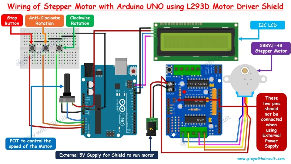
In the above wiring diagram, the Shield shown beside the Arduino should be mounted on the Arduino. It is shown like this for simplicity and for showing button and POT connections.
Pin A0 is the Analog input pin connected with the POT’s middle pin.
The other two POT pins are connected to the Arduino’s VCC and GND pins.
This POT changes the voltage on the A0 pin. According to the voltage on the A0 pin the speed of the motor changes higher the voltage higher the speed.
The button connected to the A1 pin is responsible for clockwise rotation, A2 is for Anti-clockwise rotation and A3 is to stop the motor.
The 16×2 LCD is connected to the I2C pins of Arduino UNO to display speed and motor’s direction of rotation.
A 5V unipolar stepper motor is connected at ports M3 and M4 of the shield. External 5V DC supply is provided at the EXT_PWR pin of the Shield via DC Jack.
Make sure to connect the wires in the correct order, or else the motor can be damaged.
The connections are shown in the following table:
| Arduino Pin | Connected to |
|---|---|
| 5V | Vcc pin of LCD and pin 1 of POT |
| Gnd | Gnd pin of LCD and pin 3 of POT |
| A0 | pin 2 of POT |
| A1 | Clockwise rotation Button |
| A2 | Anti-Clockwise rotation Button |
| A3 | Stop Button |
| SCL | SCL pin of LCD |
| SDA | SDA pin of LCD |
Arduino Code
The following code shows how to control a stepper motor using an Arduino UNO and an L293D motor driver shield. It includes a potentiometer for speed control and an I2C LCD for displaying the motor status. The motor can be controlled to move forward or backward using buttons.
/*
Interfacing Stepper Motor 28BYJ-48 with Arduino UNO using L293D motor Driver shield
by www.playwithcircuit.com
*/

#include <AFMotor.h>
// Library to run Stepper Motor Using Motor Driver Shield
#include <LiquidCrystal_I2C.h>
// Library to Run I2C LCD

LiquidCrystal_I2C lcd(0x27, 16, 2);  // Format -> (Address,Columns,Rows )

// Create the stepper motor object connected to M3 and M4
AF_Stepper motor(2048, 2);  // 2048 steps per rotation for 28BYJ-48, connected to motor ports 3 and 4

// Define button pins
const int forwardButtonPin = A1;
const int reverseButtonPin = A2;
const int stopButtonPin    = A3;

// Define potentiometer pin
const int potPin = A0;

// Variables to store motor state and direction
bool motorRunning = false;
int motorDirection = BACKWARD;  // FORWARD or BACKWARD

// Read the potentiometer value
int potValue;
int motorSpeed;

// Variable to store button states
bool forwardButtonState;
bool stopButtonState;
bool reverseButtonState;

// Inline function to check if button is pressed packed with debouncing logic
inline bool chkButtonState(int pinNum, int checkState, int debounceDelay) {
  if (((digitalRead(pinNum) == checkState) ? true : false) == true) {
    delay(debounceDelay);
    return (((digitalRead(pinNum) == checkState) ? (true) : (false)) == true);
  } else {
    return false;
  }
}

void setup() {
  // initialize the lcd
  lcd.init();
  // Turn on the Backlight
  lcd.backlight();
  // Clear the display buffer
  lcd.clear();

  // Set cursor (Column, Row)
  lcd.setCursor(0, 0);
  lcd.print("Stepper Motor");
  lcd.setCursor(0, 1);
  lcd.print("using Shield");

  // Set button pins as inputs
  pinMode(forwardButtonPin, INPUT_PULLUP);
  pinMode(stopButtonPin, INPUT_PULLUP);
  pinMode(reverseButtonPin, INPUT_PULLUP);

  // Start with motor off
  motor.setSpeed(0);
  motor.release();  // Stop the motor

  delay(2000);

  // Clear the display buffer
  lcd.clear();
  // Set cursor (Column, Row)
  lcd.setCursor(0, 0);
  lcd.print("Motor Direction:");
  lcd.setCursor(0, 1);
  lcd.print("Stopped   ");
}

void loop() {
  // Read the potentiometer value for changing speed as per Analog input
  potValue = analogRead(potPin);
  motorSpeed = map(potValue, 0, 1023, 3, 15);

  // Read the button states
  forwardButtonState = chkButtonState(forwardButtonPin, LOW, 20);
  reverseButtonState = chkButtonState(reverseButtonPin, LOW, 20);
  stopButtonState    = chkButtonState(stopButtonPin,    LOW, 20);

  // check for Forward run
  if (forwardButtonState && (!motorRunning || motorDirection == BACKWARD)) {
    // Set cursor (Column, Row)
    lcd.setCursor(0, 1);
    lcd.print("Clock   ");
    if (motorDirection == BACKWARD) {
      motor.setSpeed(0);
      motor.release();  // Stop the motor
      delay(1000);
    }
    motorRunning = true;
    motorDirection = FORWARD;
    motor.setSpeed(motorSpeed);
    motor.step(32, FORWARD, SINGLE);  // Move 32 steps forward single step at a time
  }
  // check for Reverse run
  else if (reverseButtonState && (!motorRunning || motorDirection == FORWARD)) {
    // Set cursor (Column, Row)
    lcd.setCursor(0, 1);
    lcd.print("Anti-Clk");
    if (motorDirection == FORWARD) {
      motor.setSpeed(0);
      motor.release();  // Stop the motor
      delay(1000);
    }
    motorRunning = true;
    motorDirection = BACKWARD;
    motor.setSpeed(motorSpeed);
    motor.step(32, BACKWARD, SINGLE);  // Move 32 steps backward single step at a time
  }
  // Stop motor
  else if (stopButtonState && motorRunning) {
    // Set cursor (Column, Row)
    lcd.setCursor(0, 1);
    lcd.print("Stopped         ");
    motorRunning = false;
    motor.setSpeed(0);
    motor.release();  // Stop the motor
  } else if (motorRunning) {
    if (motorDirection == FORWARD) {
      motor.step(32, FORWARD, SINGLE);  // Continue moving forward
    } else {
      motor.step(32, BACKWARD, SINGLE);  // Continue moving backward
    }
    motor.setSpeed(motorSpeed);
    // Set cursor (Column, Row)
    lcd.setCursor(9, 1);
    lcd.print("SPD:");
    lcd.print(((motorSpeed * 100) / 15));
    lcd.print("%  ");
  }
}
Code Explanation
First we include AFMotor and LiquidCrystal libraries, and initialize the LCD.
Then we create a stepper motor object with 2048 steps per rotation, connected to ports M3 and M4 on the motor driver shield.
Then we define the pins for the forward, reverse, and stop buttons as well as the potentiometer.
Then we initialize the variables to store the motor state, direction, speed, and button states.
In the loop sections of the code, we read the potentiometer value from analog pin A0 and mapped it to a speed range of 3 to 15. Then we check the states of the forward, reverse, and stop buttons.
- If Forward Button is pressed, the motor direction is set to forward, speed is set, and the motor moves one step forward.
- If Reverse Button is pressed, the motor direction is set to reverse, speed is set, and the motor moves one step backward.
- If Stop Button is pressed, the motor stops.
If the motor is running, it continues to move in the set direction at the set speed, and the speed is displayed on the LCD.
💡Must Read
Stepper Motor Control with Arduino
This article will give you more in-depth information about stepper motor, its working, operating modes and how to control it with Arduino using ULN2003 driver.
