
In this Arduino tutorial, we will learn how to pair two HC-05 Bluetooth modules and configure one as the Master and the other as the Slave Via AT Command. We will also learn how to establish wireless communication between two Arduino boards.
Overview
In our previous tutorial, we’ve already learned how to interface the HC-05 Bluetooth module with Arduino and set up a wireless connection between the HC-05 module and an Android phone. In that tutorial we used the module with its default configuration i.e., slave configuration.
Here we need to configure one HC-05 module as master and the other as slave, and pair them to enable wireless communication between two Arduino boards. This is known as Master-Slave configuration.
In this configuration, Master Device sends a specific command to the Slave Device and the Slave carries out the task assigned to it and replies to the Master.
Configuring the HC-05 Bluetooth Modules using AT Commands
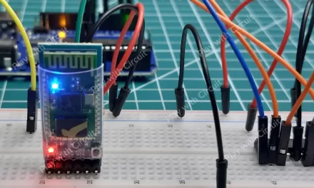
To configure the HC-05 modules, first we need to connect them to a PC through an Arduino board and use Arduino IDE Serial Monitor to send AT commands. To connect the Bluetooth module to the Arduino UNO refer the following wiring diagram.
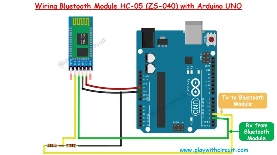
The Bluetooth module uses a serial UART interface, but the Arduino’s serial interface is used for code uploading so we’ll repurpose pin 2 and pin 3 as the Rx and Tx pins for communication with the Bluetooth module.
Since the Rx pin of the Bluetooth module is not 5V tolerant, a voltage divider circuit is used with 1kΩ and 2kΩ resistors to reduce the voltage at the Rx pin to 3.3V.
The module’s Vcc and Gnd pins are connected to the 5V and Gnd pins of the Arduino, respectively.
Refer to the below schematics for more details:
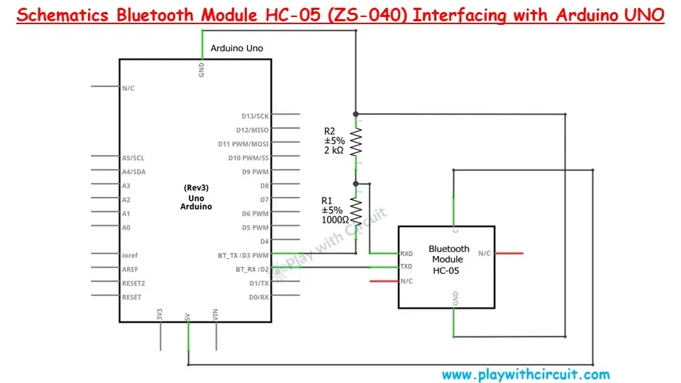
A voltage divider is created by connecting a 1kΩ and a 2kΩ resistor in series. The free end of the 1kΩ resistor is connected to pin 3 of the Arduino, while the free end of the 2kΩ resistor is connected to GND. The RXD pin of the Bluetooth module is connected to the junction between the 1kΩ and 2kΩ resistors. Pin 2 of the Arduino is directly connected to the TXD pin of the Bluetooth module.
After wiring the Bluetooth Module with Arduino, upload the following code in the Arduino UNO.
Arduino Code
This code facilitates communication with Bluetooth Module HC-05 and we will be able to configure the Bluetooth module using Arduino’s Serial Monitor.
Normally communication in command mode occurs at baud rate 38400,n,8,1 but when we upload this code in the Arduino UNO then we will be able to communicate with the module at 9600,n,8,1.
/*
Interfacing HC-05 (ZS-040) Bluetooth Module with Arduino UNO using pin 2(Rx) and 3(Tx)
by www.playwithcircuit.com

For this code to work make sure to press the button on the Bluetooth module above the Enable pin before powering the module and press it for at least 2 sec after powering up the module then release it. This will put the Bluetooth module in Command Mode.
*/

// Include Soft Serial Library. This library makes DIO pins as Serial Pins
#include <SoftwareSerial.h>

//Create software serial object to communicate with HC-05
SoftwareSerial BT_Serial(2, 3);  // Now pin 2 and pin 3 of Arduino are Serial Rx & Tx pin respectively.

char serialInputArray[100];
int counter = 0;  // Counter for getting data from bluetooth module

void setup() {

  // Open serial communication at baudrate 9600
  Serial.begin(9600);
  delay(100);       // delay before sending the data
  Serial.println("Initializing Bluetooth Module in Command Mode\n");

  // Open the soft Serial port and set the data rate for the SoftwareSerial port at 38400 to communicate with Bluetooth Module in Command Mode
  BT_Serial.begin(38400);
  delay(100);
  // Send data to HC-05 Bluetooth Module
  BT_Serial.print("AT");
  printCRLF_Bluetooth();

  // Check if data is available on Bluetooth Serial Port
  do {
    delay(10);
    // If counter is greater than 300 i.e., 3000 ms has passed then break out of Loop
    if (counter++ > 300) {
      break;
    }
  } while (BT_Serial.available() == 0);

  // If counter is greater than 300 i.e., 3000 ms has passed and data is not received
  if (counter > 300) {
    errorMsg();
  } else {
    counter = 0;
    do {
      serialInputArray[counter++] = BT_Serial.read();
      delay(10);  // delay for 10 ms for getting response if the Module is slow
    } while (BT_Serial.available() != 0);

    if (memcmp(serialInputArray, "OK", 2) == 0) {
      Serial.print("Bluetooth Module is Successfully Initialized in Command Mode\n");
    } else {
      errorMsg();
    }
  }
}

void loop() {  // run over and over
  counter = 0;
  memset(serialInputArray, 0x00, 100);

  // Get Data From Serial Terminal
  do {
    // Wait Here for getting cmd from Serial Terminal
  } while (Serial.available() == 0);
  Serial.readBytesUntil(0x0D, serialInputArray, 100);  // this '0x0D' is not added to buffer serialInputArray[]

  // Flush Data available in Serial buffer of Arduino
  flush();

  //Return that Data to PC
  printCRLF();
  Serial.print("Cmd :");
  Serial.print(serialInputArray);
  printCRLF();

  // Send data to HC-05 Bluetooth Module
  BT_Serial.print(serialInputArray);
  printCRLF_Bluetooth();

  // Wait for at least 3 seconds to get data
  do {
    delay(10);
    // If counter is greater than 300 i.e., 3000 ms has passed then break out of Loop
    if (counter++ > 300) {
      break;
    }
  } while (BT_Serial.available() == 0);

  // If counter is greater than 300 i.e., 3000 ms has passed and data is not received
  if (counter > 300) {
    Serial.print("RSP :Invalid Command");
    printCRLF();
  } else {
    Serial.print("RSP :");
    // Get Data From HC-05 and push to Serial Monitor
    do {
      Serial.write(BT_Serial.read());
      delay(10);  // delay for 10 ms for getting response if the module is slow
    } while (BT_Serial.available() != 0);
  }
}

// This function sends "\n\r" after Every Command to Bluetooth
void printCRLF_Bluetooth() {
  BT_Serial.write(13);  // Carriage Return '\r'
  BT_Serial.write(10);  // Line Feed       '\n'
}

// This function sends "\n\r" after Every Command to Serial Terminal
void printCRLF() {
  Serial.write(13);  // Carriage Return '\r'
  Serial.write(10);  // Line Feed       '\n'
}

// Flush Data available in Serial buffer of Arduino
void flush() {
  do {
    Serial.read();
    delay(10);
  } while (Serial.available() != 0);
}

// Error MSG when Communication with Bluetooth Module is not possible
void errorMsg() {
  Serial.print("Bluetooth Module is not Initialized in Command Mode, press button on Bluetooth Module\n");
  Serial.print("and then restart the Arduino and Module supply. Press it for at least 2 secs after powering up the module then release it.\n");
  Serial.print("This will put the Bluetooth module in Command Mode\n");
  Serial.print("Check the connections, maybe connections are faulty\n");
  Serial.print("If Everything is OK then Module may be faulty\n");
  printCRLF();
  while (1);
}
Code Description
The SoftwareSerial library is included to create serial communication using any of the digital pins on the Arduino. The default serial pins (0 and 1) are occupied for USB communication, so we use this library to communicate with the Bluetooth module through pins 2 and 3.
// Include Soft Serial Library, this library makes DIO pins as Serial Pins
#include <SoftwareSerial.h>
A software serial object BTSerial is created with pin 2 as Rx and pin 3 as Tx to handle communication with the HC-05 module.
//Create software serial object to communicate with HC-05
SoftwareSerial BT_Serial(2, 3);  // Now pin 2 and pin 3 of Arduino are Serial Rx & Tx pin respectively.
Initialize a character array serialInputArray[] to store input from the Serial Monitor, and a counter to keep track of time spent waiting for a response.
char serialInputArray[100];
int counter = 0;  // Counter for getting data from bluetooth module
The setup() function is used to initialize serial communications and check if the Bluetooth module is correctly initialized in command mode. First, the Serial.begin() opens the serial communication at a baud rate of 9600 to display messages via the Serial monitor, and after a brief delay, it informs the user that the Bluetooth module is being initialized in command mode.
The HC-05 Bluetooth module operates at a baud rate of 38400 in command mode, so BT_Serial.begin() sets the appropriate baud rate for communication with the module.
Next, BT_Serial.print() sends the “AT” command to the HC-05 to verify if it is in command mode. printCRLF_Bluetooth() is called to add a newline (CRLF) after the command, which is necessary for Bluetooth communication.
Then, while loop checks if the Bluetooth module sends a response. If the module takes more than 3000ms (3 seconds) to respond, the loop exits, and an error message is displayed. If the response from the module contains “OK”, it indicates successful initialization. If no valid response is received, the errorMsg() function is called to notify the user.
void setup() {

  // Open serial communication at baudrate 9600
  Serial.begin(9600);
  delay(100);       // delay before sending the data
  Serial.println("Initializing Bluetooth Module in Command Mode\n");

  // Open the soft Serial port and set the data rate for the SoftwareSerial port at 38400 to communicate with Bluetooth Module in Command Mode
  BT_Serial.begin(38400);
  delay(100);
  // Send data to HC-05 Bluetooth Module
  BT_Serial.print("AT");
  printCRLF_Bluetooth();

  // Check if data is available on Bluetooth Serial Port
  do {
    delay(10);
    // If counter is greater than 300 i.e., 3000 seconds has passed then break out of Loop
    if (counter++ > 300) {
      break;
    }
  } while (BT_Serial.available() == 0);

  // If counter is greater than 300 i.e., 3000 seconds has passed and data is not received
  if (counter > 300) {
    errorMsg();
  } else {
    counter = 0;
    do {
      serialInputArray[counter++] = BT_Serial.read();
      delay(10);  // delay for 10 ms for getting response if the Module is slow
    } while (BT_Serial.available() != 0);

    if (memcmp(serialInputArray, "OK", 2) == 0) {
      Serial.print("Bluetooth Module is Successfully Initialized in Command Mode\n");
    } else {
      errorMsg();
    }
  }
}
The loop() function repeatedly runs to allow continuous communication between the Arduino and the Bluetooth module.
First the code get command from the serial monitor. Then read the data until 0x0D (carriage return) is encountered and stores it in serialInputArray[]. After reading the input, the flush() function is used to clear any unwanted data in the serial buffer, ensuring no extra data interferes with communication. The code then prints the received command to the serial monitor.
Then the command is forwarded to the HC-05 Bluetooth module via BT_Serial.print, followed by a newline (CRLF) using printCRLF_Bluetooth().
Then while loop waits for the Bluetooth module to send a response. The counter limits the waiting time to 3 seconds, ensuring the program doesn’t hang indefinitely. Once a response is received from the Bluetooth module, it is displayed on the Serial Monitor in real-time.
If there’s an issue with initializing the Bluetooth module in command mode, this function prints a series of instructions and error messages to the serial terminal.
void loop()
{ // run over and over
  counter = 0;
  memset(serialInputArray, 0x00, 100);

  // Get Data From Serial Terminal
  do {
    // Wait Here for getting cmd from Serial Terminal
  } while (Serial.available() == 0);
  Serial.readBytesUntil(0x0D, serialInputArray, 100);  // this '0x0D' is not added to buffer serialInputArray[]

  // Flush Data available in Serial buffer of Arduino
  flush();

  //Return that Data to PC
  printCRLF();
  Serial.print("Cmd :");
  Serial.print(serialInputArray);
  printCRLF();

  // Send data to HC-05 Bluetooth Module
  BT_Serial.print(serialInputArray);
  printCRLF_Bluetooth();

  // Wait for at least 3 seconds to get data
  do {
    delay(10);
    // If counter is greater than 300 i.e., 3000 ms has passed then break out of Loop
    if (counter++ > 300) {
      break;
    }
  } while (BT_Serial.available() == 0);

  // If counter is greater than 300 i.e., 3000 ms has passed and data is not received
  if (counter > 300) {
    Serial.print("RSP :Invalid Command");
    printCRLF();
  } else {
    Serial.print("RSP :");
    // Get Data From HC-05 and push to Serial Monitor
    do {
      Serial.write(BT_Serial.read());
      delay(10);  // delay for 10 ms for getting response if the module is slow
    } while (BT_Serial.available() != 0);
  }
}

// This function sends "\n\r" after Every Command to Bluetooth
void printCRLF_Bluetooth() {
  BT_Serial.write(13);  // Carriage Return '\r'
  BT_Serial.write(10);  // Line Feed       '\n'
}

// This function sends "\n\r" after Every Command to Serial Terminal
void printCRLF() {
  Serial.write(13);  // Carriage Return '\r'
  Serial.write(10);  // Line Feed       '\n'
}

// Flush Data available in Serial buffer of Arduino
void flush() {
  do {
    Serial.read();
    delay(10);
  } while (Serial.available() != 0);
}

// Error MSG when Communication with Bluetooth Module is not possible
void errorMsg() {
  Serial.print("Bluetooth Module is not Initialized in Command Mode, press button on Bluetooth Module\n");
  Serial.print("and then restart the Arduino and Module supply. Press it for at least 2 secs after powering up the module then release it.\n");
  Serial.print("This will put the Bluetooth module in Command Mode\n");
  Serial.print("Check the connections, maybe connections are faulty\n");
  Serial.print("If Everything is OK then Module may be faulty\n");
  printCRLF();
  while (1);
}
Putting Bluetooth Module in Command Mode
Before assigning the role (Slave/Master) to the Bluetooth Module, we need to put the Bluetooth Module in Command mode so that role-specific commands can be sent.
Step 1 Wire the Bluetooth Module with Arduino as per the circuit diagram and upload the code in Arduino UNO.
Step 2 When the code is uploaded successfully remove the USB cable from Laptop/PC.
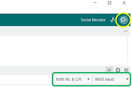
Step 3 Open the Serial monitor window in Arduino IDE, and make sure the Baud rate of the Serial monitor is 9600,n,8,1, and Line Ending is set to both NL and CR.
Step 4 Press the button on the Bluetooth module and connect the USB cable to the Laptop/PC while the button is pressed.
Step 5 Press the button on the module till the below message appears on the Serial Terminal Window. If the message in your terminal is the same as shown below, the module is now in command mode and Slave/Master specific commands can be sent.
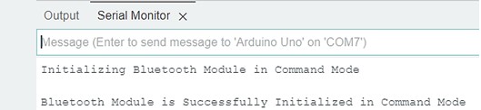
Step 6 If the message is not displayed as shown in Step 5 then restart the sequence from Step 3.
Configuring the Bluetooth Module for the Slave Role
By default, the HC-05 Bluetooth module is in Slave Role and the default parameters of the HC-05 Bluetooth Module are as follows:
- Baud Rate: 9600 bps
- Data: 8 bits
- Stop Bits: 1 bit
- Parity: None
- Handshake: None
- Passkey: 1234( or 0000)
- Device Name: HC-05
When the module successfully enters the command mode, follow the below steps to configure the module for the slave role:
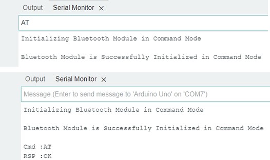
Step 1 Test Communication: The Module and Arduino can communicate successfully in command mode. It’s time to check it manually with the Serial Monitor window.
Type “AT” in the Serial Monitor and press Enter. You should get back “OK” as a response.
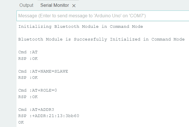
Step 2 Change Name: Type “AT+NAME=SLAVE” and press Enter to change the module’s name. You should receive “OK” as a response.
Step 3 Set Role to Slave: Type “AT+ROLE=0” and press Enter to set the role of the module to slave. You should receive “OK” as a response.
Step 4 Get Address: Type “AT+ADDR?” and press Enter to display the module’s address in hexadecimal format. Write down this address as we will need it for configuring the master device.
Step 5 Disconnect Module: Remove the USB cable from the PC/Laptop and remove the Slave HC-05 module from the Circuit.
Configuring the Bluetooth Module for the Master Role
Connect another module in the circuit and put the module in command mode as we have already done for the Slave HC-05 module.
When the module successfully enters the command mode, send the following commands to configure the module for the Master role.
Step 1 Test Communication: The Module and Arduino can communicate successfully in command mode. It’s time to check it manually with the serial Monitor window.
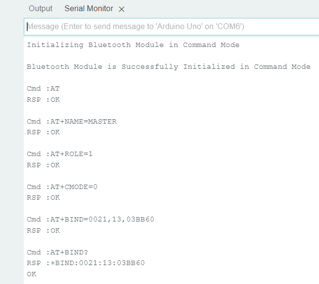
Type “AT” in the Serial Monitor and press Enter. You should get back “OK” as a response.
Step 2 Change Name: Type “AT+NAME=MASTER” and press Enter to change the module’s name. You should receive “OK” as a response.
Step 3 Set Role to Master: Type “AT+ROLE=1” and press Enter to set the role of the module to master. You should receive “OK” as a response.
Step 4 Set Connection Mode: Type “AT+CMODE=0” and press Enter to set the connection mode of the module to a fixed address. You should receive “OK” as a response.
Step 5 Pair with Slave: Type “AT+BIND=0021,13,03BB60” (replace with your slave module’s address, in our case the Slave module’s address is 21:13:3bb60) and press Enter. This command will pair the master module with the slave module. You should receive “OK” as a response.
❕Note
The value before the first comma should be 4 characters hence two zeroes were added before 21 also, after the second comma a zero is inserted before 3BB60 to make a total of 6 bytes. Also, note that the hex character ‘b’ can be small or in the capital letter and have no effect.
After sending this command check if the correct address has been sent hence Type “AT+BIND?” and press Enter to check the slave address. If the response is all zeroes or another address is shown then it means the BIND command has failed so repeat step 5 again.
Step 6 Disconnect Module: Remove the USB cable from the PC/Laptop and remove the Slave HC-05 module from the Circuit.
HC-05 AT Commands
For your reference, we’ve provided a list of HC-05 AT commands.
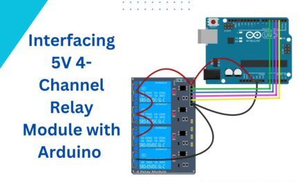
Master-Slave Communication Between Two Arduino Boards using HC-05 Bluetooth Modules
Now let’s set up wireless communication between two Arduino UNO boards using the HC-05 Bluetooth module.
There will be two circuits one for the Master device and another one will be for the Slave device. The Master device will send the command to the Slave device and the Slave device will work according to the commands received and send a reply to the Master.
Understanding the Master-Slave Communication
In Master-Slave communication, the controlling circuit, known as the Master circuit, sends the command to another circuit that carries out the task, known as the Slave. There can be multiple slave circuits and single master circuit but in this article, we will be controlling only one slave circuit. The communication will be wireless using the Bluetooth Module. Hence we need two Bluetooth modules, one should be configured as master and another one as slave. Let’s understand how to operate the Master-Slave circuit.
The Master HC-05 tries to establish a connection with the Slave HC-05 module, hence power to the Slave board should be turned ON before the Master board.
As we have already configured both the modules. Hence as soon as the Master and Slave circuits are turned on the Master initiates the connection and connects with the Slave as the Slave’s address is already provided to the Master during its role assignment.
When the Master is successfully connected with the Slave board, on board LED on the Master Arduino turns ON.
We will understand this with a practical example. We will control a 12V DC motor connected to the Slave board circuit using the Buttons and a POT connected to the Master board circuit.
Three buttons are connected to the Master board:
- The first button rotates the motor in the clockwise direction
- The second button stops the Motor
- The third button rotates the Motor in the anticlockwise direction.
The Pot is used to control the speed of the Motor.
The master will send the following commands to the slave board:
Alive command: This command is sent to check if the slave is connected to the Master or not. When the response is received, it means the connection has been successfully established.
CMD: *ALIVE#
RESP: *OK#
Here ‘*’ and ‘#’ are the start and end characters.
Motor Control Command: This command controls the motor connected to the Slave board. When the response is received it means the command has been received successfully.
CMD: * DIRECTION_BYTE, SPEED_BYTE#
RESP: *OK#
Example: *1,255#
Hardware and Software Requirements for both Master and Slave Circuits
Hardware Requirement
| Component Name | Quantity | Remarks | Where to Buy |
|---|---|---|---|
| Arduino UNO R3 | 1 | Revision R3 | Amazon.com / Amazon.in / Banggood |
| HC-05 Bluetooth Module | 2 | It should have AT mode button and should have 6 pins. | Amazon.com / Amazon.in |
| Resistance | 4 | 1k and 2k | Amazon.com / Amazon.in / Banggood |
| L293D | 1 | Motor Driver IC | Amazon.com / Amazon.in |
| Breadboard | 2 | Full size | Amazon.com / Amazon.in / Banggood |
| USB Cable Type A to B | 1 | for programming Arduino UNO | Amazon.com / Amazon.in |
| Jumper Wires | multiple | For Breadboard and Arduino Connections | Amazon.com / Amazon.in / Banggood |
| 12V Supply Adapter | 3 | For providing power to Arduino and For providing supply to L293d Motor Driver IC | Amazon.com / Amazon.in |
| DC Fan | 1 | 12 V DC FAN | Amazon.com / Amazon.in |
| Push Button | 3 | To control Motor | Amazon.com / Amazon.in |
| Pot | 1 | 10k pot to control the speed of motor | Amazon.com / Amazon.in |
Software Requirement
- Arduino IDE, Version 2.1.1 or above installed on your PC
- SoftwareSerial Library by Arduino.
Master Board Wiring Diagram
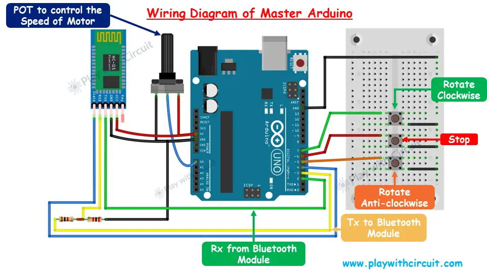
Apart from the Bluetooth connections as described above in previous circuit, a pot is connected here at pin A0, which is used to control the speed of the DC motor connected at Slave. It gets the analog value and transmits it over the Bluetooth module in the form of command to the Slave board.
Three push buttons connected at pins 7, 6, and 5 are used to rotate the motor in clockwise direction, stop the motor, and rotate it in an anticlockwise direction respectively.
Also, we will use an on board LED present on Arduino connected to pin 13. It indicates the following states of the board:
- If the Master board is successfully connected with the Slave board, then the LED turns ON and should remain ON till the Master circuit is ON.
- If the Master board is disconnected from the Slave board then the LED turns OFF .
- If this LED is blinking then it means there is a drop in frames of command/response so we need to place the Slave board and Master board closer so there will be proper communication between the two boards.
Refer to below schematic diagram for more detail:
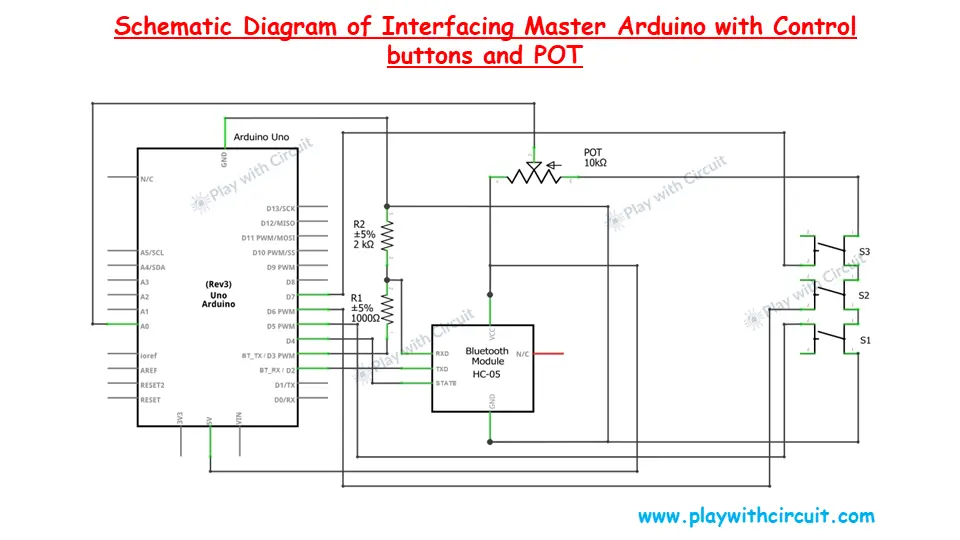
Master Arduino Code
This code allows the user to control the motor’s direction (clockwise or anticlockwise) and speed using buttons and a potentiometer connected to the Master Arduino. The motor is connected with Arduino in slave’s circuit using L293D IC.
/*
Interfacing HC-05 (ZS-040) Bluetooth Module with Slave Arduino UNO using pin 2(Rx) and 3(Tx) and Control the Motor using another Arduino UNO, which acts as Master
by www.playwithcircuit.com

This is the Master Arduino Code.
*/

// Include Soft Serial Library. This library makes DIO pins as Serial Pins
#include <SoftwareSerial.h>
//Create software serial object to communicate with HC-05
// Now pin 2 and pin 3 of Arduino are Serial Rx & Tx pin Respectively
SoftwareSerial BTSerial(2, 3);

// Define MACROS related to communication
#define START_CHAR '*'
#define END_CHAR '#'
#define MAX_BUFFFER 8

// Define the pins connected to buttons or POT to control the Motor connected with Slave
// button to Rotate motor in Clockwise Direction
#define ROTATE_CLOCKWISE 7
// button to Stop motor
#define ROTATE_STOP 6
// button to Rotate motor in Anticlockwise Direction
#define ROTATE_ANTI_CLOCKWISE 5
// Pot to control motor's Speed
#define ROTATE_SPEED A0
// LED to Indicate successful communication
#define LED_GREEN 13
// State Pin to check if module is connected to Slave
// if state pin is high it means Master module is connected to Slave module
#define STATE_PIN 4

// Declare variables related to communication with Arduino Master
char serialInput;
int dataIndex = 0;
int rspSize = 0;
bool bo_cmd_ok = false;
// Whether the string receiving is completed.
bool dataRcvd = false;
// To receive Raw response
char dataBuffer[MAX_BUFFFER] = { 0 };
// To save exact response
char rspBuffer[MAX_BUFFFER] = { 0 };

// Alive command
const char aliveCmd[MAX_BUFFFER] = {START_CHAR, 'A', 'L', 'I', 'V', 'E', END_CHAR, 0x00};
// Standard OK response
const char stdRsp[5] = {START_CHAR, 'O', 'K', END_CHAR, 0x00};

// Declare variable related to motor control
int motor_Speed = 0;
int motor_direction = 0;

// Function to clear bluetooth Buffer
void flushBTRcv();
// Function to receive Slave's Response
int checkResponse(void);

// Inline function to check if button is pressed packed with debouncing logic
inline bool chkButtonState(int pinNum, int checkState, int debounceDelay) {
  if (((digitalRead(pinNum) == checkState) ? true : false) == true) {
    delay(debounceDelay);
    return (((digitalRead(pinNum) == checkState) ? true : false) == true);
  } else {
    return false;
  }
}

void setup() {
  int retVal = 1;
  // Initialize motor control pins as INPUTS
  pinMode(ROTATE_CLOCKWISE, INPUT_PULLUP);
  pinMode(ROTATE_STOP, INPUT_PULLUP);
  pinMode(ROTATE_ANTI_CLOCKWISE, INPUT_PULLUP);
  pinMode(ROTATE_SPEED, INPUT);
  pinMode(STATE_PIN, INPUT_PULLUP);
  // Initialize Status LED as OUTPUT and Turn it OFF
  pinMode(LED_GREEN, OUTPUT);
  digitalWrite(LED_GREEN, LOW);
  // Begin the soft Serial port and set the data rate for the SoftwareSerial port at 9600 to communicate with Bluetooth Module in Data Mode
  BTSerial.begin(9600);
  // wait for state pin to turn HIGH else remain in this loop
  while(chkButtonState(STATE_PIN,LOW,0));
  do {
    // provide a delay of 200 ms
    delay(200);
    //! Send Alive Command
    BTSerial.print(aliveCmd);
    retVal = checkResponse();
    if (retVal == 1) {
      // Turn Green LED OFF
      digitalWrite(LED_GREEN, LOW);
    } else {
      // Turn GREEN LED ON
      digitalWrite(LED_GREEN, HIGH);
      break;
    }
  } while (retVal);
}

void loop() {
  // variable to read POT input
  int potValue = 0;
  // return value of function checkResponse()
  int retVal = 1;
  // Read Motor Direction

  // check if Clockwise rotation button is pressed
  if (chkButtonState(ROTATE_CLOCKWISE, LOW, 20) == true) {
    motor_direction = 1;
  }
  // check if Anticlockwise rotation button is pressed
  else if (chkButtonState(ROTATE_ANTI_CLOCKWISE, LOW, 20) == true) {
    motor_direction = 2;
  }
  // check if Stop rotation button is pressed
  else if (chkButtonState(ROTATE_STOP, LOW, 20) == true) {
    motor_direction = 0;
  }

  // Read the value from the potentiometer
  potValue = analogRead(ROTATE_SPEED);
  motor_Speed = map(potValue, 0, 1023, 0, 255);

  //Send Motor Control command to Slave
  BTSerial.print(START_CHAR);
  BTSerial.print(motor_direction);
  BTSerial.print(',');
  BTSerial.print(motor_Speed);
  BTSerial.print(END_CHAR);

  // Check Response
  retVal = checkResponse();
  if (retVal == 1) {
    // Turn Green OFF
    digitalWrite(LED_GREEN, LOW);
  } else {
    // Turn GREEN LED ON
    digitalWrite(LED_GREEN, HIGH);
  }
  // Send next command after 100 ms
  delay(100);
}

// Flush Extra character from BT Rx buffer
void flushBTRcv() {
  char ret_char;
  while (BTSerial.available() > 0) {
    ret_char = BTSerial.read();
  }
}

// This function is used to receive "*OK#" response from Slave
// If exact response is received it returns 0 else it returns 1
int checkResponse(void) {
  int retVal = 1;
  int counter = 0;
  delay(10);            // delay to get first character
  // Get Data From HC-05
  while (BTSerial.available()) {
    // get the new byte
    serialInput = BTSerial.read();
    dataBuffer[dataIndex++] = serialInput;
    // If the incoming character is a END_CHAR character, set a flag so the main loop can do something about it
    if ((serialInput == END_CHAR) || (dataIndex == MAX_BUFFFER)) {
      dataIndex = 0;
      dataRcvd = true;
      flushBTRcv();
    }
    delay(10);              // 10 ms delay after receiving every character
    if (counter++ > 350) {       // this provides delay of 3500 ms or 3.5 seconds
      dataRcvd = false;
      dataIndex = 0;
      flushBTRcv();
      break;
    }
  }

  if (dataRcvd == true) {
    rspSize = 0;
    // Check for start and end character
    memset(rspBuffer, 0x00, sizeof(rspBuffer));

    // Extract command from RAW data sent
    for (int i = 0; i < MAX_BUFFFER; i++) {
      if (dataBuffer[i] == START_CHAR) {
        for (int j = 0; j < MAX_BUFFFER; j++) {
          rspBuffer[j] = dataBuffer[j + i];
          rspSize++;
          if (rspBuffer[j] == END_CHAR) {
            bo_cmd_ok = true;
            break;
          }
        }
      }
    }
    if (bo_cmd_ok == true) {
      //! check for Command's Response if its OK it means Slave is connected to Master
      if (memcmp(rspBuffer, stdRsp, 4) == 0) {
        // Reply OK
        retVal = 0;
      } else {
        retVal = 1;
      }
    } else {
      retVal = 1;
    }
    dataRcvd = false;
    bo_cmd_ok = false;
    memset(dataBuffer, 0x00, sizeof(dataBuffer));
  } else {
    retVal = 1;
  }

  // reset array and variables
  memset(dataBuffer, 0x00, sizeof(dataBuffer));
  bo_cmd_ok = false;
  dataRcvd =false;

  // return result
  return retVal;
}
Code Description
The SoftwareSerial library is included to allow the use of digital pins (pins 2 and 3) as software serial communication ports for the HC-05 Bluetooth module.
BTSerial is created to allow communication with the HC-05 module on pins 2 (Rx) and 3 (Tx).
// Include Soft Serial Library. This library makes DIO pins as Serial Pins
#include <SoftwareSerial.h>
//Create software serial object to communicate with HC-05
// Now pin 2 and pin 3 of Arduino are Serial Rx & Tx pin Respectively
SoftwareSerial BTSerial(2, 3);
In the following code lines, START_CHAR & END_CHAR define the start and end of each message sent between the Master and Slave.
MAX_BUFFER define the buffer size for communication which is set to 8 characters.
// Define MACROS related to communication
#define START_CHAR '*'
#define END_CHAR '#'
#define MAX_BUFFFER 8
Now we define pins 7, 6, and 5 which are used for controlling motor direction (clockwise, stop and anti-clockwise). Then we define pin A0 which is connected to a potentiometer (analog input). It controls the speed of the motor.
Then we define green LED (pin 13) which indicates successful communication between the Master and Slave devices. If the LED is lit, communication is successful. Then we define State Pin which is used to check whether the Master module is connected to the Slave module.
// Define the pins connected to buttons or POT to control the Motor connected with Slave
// button to Rotate motor in Clockwise Direction
#define ROTATE_CLOCKWISE 7
// button to Stop motor
#define ROTATE_STOP 6
// button to Rotate motor in Anticlockwise Direction
#define ROTATE_ANTI_CLOCKWISE 5
// Pot to control motor's Speed
#define ROTATE_SPEED A0
// LED to Indicate successful communication
#define LED_GREEN 13
// State Pin to check if module is connected to Slave
// if state pin is high it means Master module is connected to Slave module
#define STATE_PIN 4
In the following code lines, we declare variables related to communication.
serialInput is used to store individual characters received from the master device via serial communication.
dataIndex keeps track of the current position (index) in the buffer where the next received character will be stored.
rspSize is used to store the size of the response being received from the master, helping to determine how many bytes of data need to be processed.
bo_cmd_ok indicates whether the received command from the master is valid or “OK.”
dataRcvd tracks whether a complete string (message) has been received from the master.
dataBuffer array is used to store the raw data received from the master during serial communication. MAX_BUFFFER defines the maximum size of the buffer.
rspBuffer array is used to store the exact response after processing the raw data parsing from dataBuffer.
// Declare variables related to communication
char serialInput;
int dataIndex = 0;
int rspSize = 0;
bool bo_cmd_ok = false;
// Whether the string receiving is completed.
bool dataRcvd = false;
// To receive Raw response
char dataBuffer[MAX_BUFFFER] = { 0 };
// To save exact response
char rspBuffer[MAX_BUFFFER] = { 0 };
In the following code lines, aliveCmd command is used to check if the Slave is ready to receive commands. stdRsp is used to acknowledge that communication or a command was received successfully with an “OK” message.
// Alive command
const char aliveCmd[MAX_BUFFFER] = {START_CHAR, 'A', 'L', 'I', 'V', 'E', END_CHAR, 0x00};
// Standard OK response
const char stdRsp[5] = {START_CHAR, 'O', 'K', END_CHAR, 0x00};
Here motor_Speed is used to store the speed of the motor. motor_direction represents the direction in which the motor will rotate.
// Declare variable related to motor control
int motor_Speed = 0;
int motor_direction = 0;flushBTRcv() function is used to clear the Bluetooth receive buffer. checkResponse()
// Function to clear bluetooth Buffer
void flushBTRcv();
// Function to receive Slave's Response
int checkResponse(void);
The following inline function is used to ensure that button presses are stable and not affected by noise (debouncing). It reads the button state, introduces a delay, and checks again to confirm a valid press.
// Inline function to check if button is pressed packed with debouncing logic
inline bool chkButtonState(int pinNum, int checkState, int debounceDelay) {
  if (((digitalRead(pinNum) == checkState) ? true : false) == true) {
    delay(debounceDelay);
    return (((digitalRead(pinNum) == checkState) ? true : false) == true);
  } else {
    return false;
  }
}
In setup(), motor control pins and status LED are initialized. It sets communication with the Bluetooth module, and checks the connection with the Slave device before proceeding.
BTSerial.begin sets up serial communication with the Bluetooth module using SoftwareSerial at a baud rate of 9600. This enables communication with the Bluetooth module in data mode.
The chkButtonState() function ensures that the Master remains in a loop until the Bluetooth module indicates a connection by checking state pin. Once connected, the Master sends an “Alive” command to the Slave and waits for a response. If the response is received, the LED turns off; otherwise, it turns on.
void setup() {
  int retVal = 1;
  // Initialize motor control pins as INPUTS
  pinMode(ROTATE_CLOCKWISE, INPUT_PULLUP);
  pinMode(ROTATE_STOP, INPUT_PULLUP);
  pinMode(ROTATE_ANTI_CLOCKWISE, INPUT_PULLUP);
  pinMode(ROTATE_SPEED, INPUT);
  pinMode(STATE_PIN, INPUT_PULLUP);
  // Initialize Status LED as OUTPUT and Turn it OFF
  pinMode(LED_GREEN, OUTPUT);
  digitalWrite(LED_GREEN, LOW);
  // Begin the soft Serial port and set the data rate for the SoftwareSerial port at 9600 to communicate with Bluetooth Module in Data Mode
  BTSerial.begin(9600);
  // wait for state pin to turn HIGH else remain in this loop
  while(chkButtonState(STATE_PIN,LOW,0));
  do {
    // provide a delay of 200 ms
    delay(200);
    //! Send Alive Command
    BTSerial.print(aliveCmd);
    retVal = checkResponse();
    if (retVal == 1) {
      // Turn Green LED OFF
      digitalWrite(LED_GREEN, LOW);
    } else {
      // Turn GREEN LED ON
      digitalWrite(LED_GREEN, HIGH);
      break;
    }
  } while (retVal);
}
Variables potValue stores the potentiometer value, and retVal is used to store the return value from the checkResponse() function.
The direction of the motor is determined by checking if the corresponding button (Clockwise, Anti-clockwise, or Stop) is pressed. The function chkButtonState() checks if the button is pressed using debouncing logic.
motor_direction = 1for clockwise rotation.motor_direction = 2for anticlockwise rotation.motor_direction = 0to stop the motor.
Then the value from the potentiometer (ROTATE_SPEED) is read using analogRead(). The value is mapped from a range of 0-1023 (analog input range) to 0-255 (motor speed range).
void loop() {
  // variable to read POT input
  int potValue = 0;
  // return value of function checkResponse()
  int retVal = 1;
  // Read Motor Direction

  // check if Clockwise rotation button is pressed
  if (chkButtonState(ROTATE_CLOCKWISE, LOW, 20) == true) {
    motor_direction = 1;
  }
  // check if Anticlockwise rotation button is pressed
  else if (chkButtonState(ROTATE_ANTI_CLOCKWISE, LOW, 20) == true) {
    motor_direction = 2;
  }
  // check if Stop rotation button is pressed
  else if (chkButtonState(ROTATE_STOP, LOW, 20) == true) {
    motor_direction = 0;
  }

  // Read the value from the potentiometer
  potValue = analogRead(ROTATE_SPEED);
  motor_Speed = map(potValue, 0, 1023, 0, 255);
Now, the code sends a predefined start character to the Slave device via Bluetooth.
motor_direction is used to send the motor’s direction to the Slave device.
motor_Speed is used to send the motor’s speed to the Slave device. Finally, the end character is sent to signal the end of the command.
  //Send Motor Control command to Slave
  BTSerial.print(START_CHAR);
  BTSerial.print(motor_direction);
  BTSerial.print(',');
  BTSerial.print(motor_Speed);
BTSerial.print(END_CHAR);- The function
checkResponse()is called to check if the slave device sent a valid response. - If the response is valid, the green LED is turned ON. If not, it is turned OFF.
  // Check Response
  retVal = checkResponse();
  if (retVal == 1) {
    // Turn Green OFF
    digitalWrite(LED_GREEN, LOW);
  } else {
    // Turn GREEN LED ON
    digitalWrite(LED_GREEN, HIGH);
  }
  // Send next command after 100 ms
  delay(100);
}
The flushBTRcv() function clears any extra characters from the Bluetooth receive buffer. It reads all available data in the buffer using a loop and discards it by storing each character in a temporary variable (ret_char).
// Flush Extra character from BT Rx buffer
void flushBTRcv() {
  char ret_char;
  while (BTSerial.available() > 0) {
    ret_char = BTSerial.read();
  }
}
The checkResponse() function is used to receive a response from the Slave device via Bluetooth, specifically looking for the “*OK#” response. A short delay is added to allow the first character to be received. Then, it enters a loop that reads data from the Bluetooth module (HC-05) byte by byte, storing it in the dataBuffer. The function continues reading until it detects an end character or fills the buffer.
If the expected “*OK#” response is found, the function returns 0, indicating successful communication. Otherwise, it returns 1, signaling that the expected response was not received.
// This function is used to receive "*OK#" response from Slave
// If exact response is received it returns 0 else it returns 1
int checkResponse(void) {
  int retVal = 1;
  int counter = 0;
  delay(10);            // delay to get first character
  // Get Data From HC-05
  while (BTSerial.available()) {
    // get the new byte
    serialInput = BTSerial.read();
    dataBuffer[dataIndex++] = serialInput;
The following code checks if the received message ends with the END_CHAR or if the buffer is full. Once the message is complete, it clears the Bluetooth receive buffer.
A short delay ensures proper character reception, and a timeout prevents waiting indefinitely for data.
If a valid message is received, it looks for a command starting with START_CHAR and ending with END_CHAR. Once a complete command (from start to end) is found, it sets the flag bo_cmd_ok to indicate that the command is valid.
    // If the incoming character is a END_CHAR character, set a flag so the main loop can do something about it
    if ((serialInput == END_CHAR) || (dataIndex == MAX_BUFFFER)) {
      dataIndex = 0;
      dataRcvd = true;
      flushBTRcv();
    }
    delay(10);              // 10 ms delay after receiving every character
    if (counter++ > 350) {       // this provides delay of 3500 ms or 3.5 seconds
      dataRcvd = false;
      dataIndex = 0;
      flushBTRcv();
      break;
    }
  }

  if (dataRcvd == true) {
    rspSize = 0;
    // Check for start and end character
    memset(rspBuffer, 0x00, sizeof(rspBuffer));

    // Extract command from RAW data sent
    for (int i = 0; i < MAX_BUFFFER; i++) {
      if (dataBuffer[i] == START_CHAR) {
        for (int j = 0; j < MAX_BUFFFER; j++) {
          rspBuffer[j] = dataBuffer[j + i];
          rspSize++;
          if (rspBuffer[j] == END_CHAR) {
            bo_cmd_ok = true;
            break;
          }
        }
      }
} if (bo_cmd_ok == true) {
//! check for Command's Response if its OK it means Slave is connected to Master
if (memcmp(rspBuffer, stdRsp, 4) == 0) {
// Reply OK
retVal = 0;
} else {
retVal = 1;
}
} else {
retVal = 1;
}
dataRcvd = false;
bo_cmd_ok = false;
memset(dataBuffer, 0x00, sizeof(dataBuffer));
} else {
retVal = 1;
}
// reset array and variables
memset(dataBuffer, 0x00, sizeof(dataBuffer));
bo_cmd_ok = false;
dataRcvd =false;
// return result
return retVal;
}Slave Board Wiring Diagram
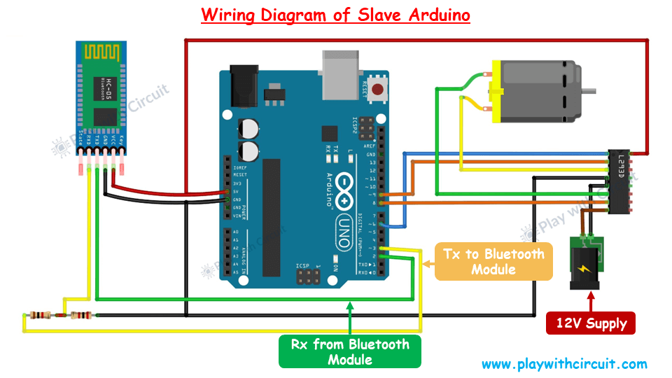
Apart from the Bluetooth module connections, an L293D IC is connected to a Slave Arduino board to control the 12V DC motor.
Connect pin 14 of the L293D IC to VCC, and pins 4 and 5 to the Arduino’s GND.
Link Arduino’s PWM pin 6 to pin 1 (the Enable pin) of the L293D IC.
Attach the 12V DC motor fan to pins 3 and 6 of the L293D motor driver IC.
Connect pins 8 and 9 of the Arduino to input pins 2 and 1 of the L293D IC, respectively.
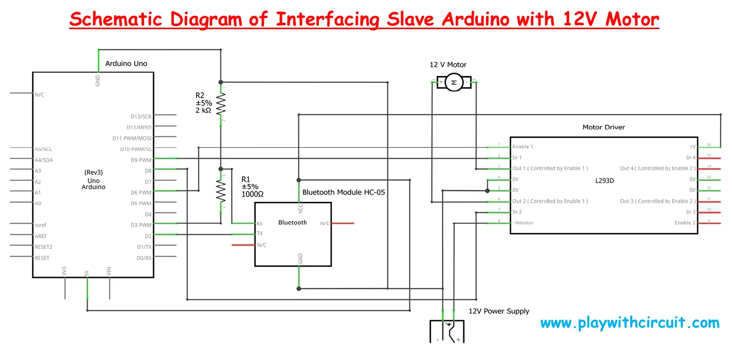
Finally, connect the positive terminal of the 12V power supply for the DC fan to pin 8 of the L293D IC, and the negative terminal to GND at pins 4 and 5. For more information refer following schematic:
❕Note
The Arduino and fan should have separate power supply of 12 volts, because when the fan’s speed increases, it may draw more current, potentially reducing the current available to the Arduino and Bluetooth module. This could lead to frequent disconnection of Bluetooth from the Master board. Therefore, it’s recommended to use separate power supplies, while ensuring that the grounds of both power supplies are connected.
Slave Arduino Code
This code is designed for the Slave Arduino that controls a motor (fan) using commands received from a Master Arduino via an HC-05 Bluetooth module. It interfaces with an L293D motor driver to control the fan’s direction and speed.
/*
Interfacing HC-05 (ZS-040) Bluetooth Module with Slave Arduino UNO using pin 2(Rx) and 3(Tx) and Control the Fan connected to Motor using another Arduino UNO, which acts as Master
by www.playwithcircuit.com

This is Slave Arduino Code.
*/

// Include Soft Serial Library, this library makes DIO pins as Serial Pins
#include <SoftwareSerial.h>
//Create software serial object to communicate with HC-05
SoftwareSerial BTSerial(2,3);  // Now pin 2 and pin 3 of Arduino are Serial Rx & Tx pin respectively

// Define MACROS related to communication
#define START_CHAR '*'
#define END_CHAR '#'
#define MAX_BUFFFER 14
#define MAX_INDEX 2

#define MOTOR_DIRECTION_INDEX 0
#define MOTOR_SPEED_INDEX 1

// Define the pins connected to the L293D IC
#define MOTOR_EN 6   // Enable pin for Motor A
#define MOTOR_IN1 9  // Input 1 for Motor A
#define MOTOR_IN2 8  // Input 2 for Motor A

// Declare variables related to communication with Master Arduino
char serialInput;
int dataIndex = 0;
char databuffer[MAX_BUFFFER] = { 0 };
char cmdbuffer[MAX_BUFFFER] = { 0 };
bool dataRcvd = false;  // whether the string receiving is completed.

char char_array[MAX_INDEX][4] = { 0 };
int int_array[MAX_INDEX] = { 0 };

int index;
int cmdsize = 0;
bool bo_cmd_ok = false;
int row = 0;
int row_index = 0;

// Alive command
const char aliveCmd[8] = { START_CHAR, 'A', 'L', 'I', 'V', 'E', END_CHAR, 0x00 };
// Standard OK response
const char stdRsp[5] = { START_CHAR, 'O', 'K', END_CHAR, 0x00 };

// Declare variables related to motor control
int motorSpeed = 0;
char previous_direction = 0;  // to store previous direction
bool one_time_flag = true;

int AsciitoInt(char* char_array);
void flushBTRcv();

void setup() {
  // Initialize motor control pins as outputs
  pinMode(MOTOR_EN, OUTPUT);
  pinMode(MOTOR_IN1, OUTPUT);
  pinMode(MOTOR_IN2, OUTPUT);
  // Begin the soft Serial port and set the data rate for the SoftwareSerial port at 9600 to communicate with Bluetooth Module in Data Mode
  BTSerial.begin(9600);
  // provide stability delay of 200 ms
  delay(200);
  // Set initial motor speed to zero
  analogWrite(MOTOR_EN, 0);
}

void loop() {
  // Get Data From HC-05
  while (BTSerial.available()) {
    // get the new byte
    serialInput = BTSerial.read();
    databuffer[dataIndex++] = serialInput;
    delay(10); // delay of 10 ms to get next character
    // if the incoming character is a END_CHAR character or databuffer is full
    // set a flag to true so that buffer shall not overflow
    if ((serialInput == END_CHAR) || (dataIndex == MAX_BUFFFER)) {
      dataIndex = 0;
      dataRcvd = true;
      flushBTRcv();
    }
  }

  if (dataRcvd == true) {
    cmdsize = 0;
    // Check for start and end character
    memset(cmdbuffer, 0x00, sizeof(cmdbuffer));

    // Extract command from RAW data sent
    for (int i = 0; i < MAX_BUFFFER; i++) {
      if (databuffer[i] == START_CHAR) {
        for (int j = 0; j < MAX_BUFFFER; j++) {
          cmdbuffer[j] = databuffer[j + i];
          cmdsize++;
          if (cmdbuffer[j] == END_CHAR) {
            bo_cmd_ok = true;
            break;
          }
        }
      }
      if (bo_cmd_ok == true) {
        break;
      }
    }
    dataRcvd = false;
    memset(databuffer, 0x00, sizeof(databuffer));

    if (bo_cmd_ok == true) {
      //! check for Alive Command
      if (memcmp(cmdbuffer, aliveCmd, 7) == 0) {
        // Reply OK
        BTSerial.print(stdRsp);
        bo_cmd_ok = false;
      }
    }
  }

  // if command is successfully extracted from data buffer and saved in command buffer
  if (bo_cmd_ok == true) {
    // Reset all variables and array
    index = 0;
    row = 0;
    row_index = 0;
    bo_cmd_ok = false;
    memset(char_array, 0x00, sizeof(char_array));
    memset(int_array, 0x00, sizeof(int_array));

    // as index 0 is the start character hence it is incremented by 1
    index++;

    // save two different commands in character array, one is motor status and another is motor speed
    for (; index < cmdsize; index++) {
      if (cmdbuffer[index] == ',' || cmdbuffer[index] == '#') {
        row++;
        row_index = 0;
        continue;
      } else {
        char_array[row][row_index++] = cmdbuffer[index];
      }
    }

    for (int i = 0; i < MAX_INDEX; i++) {
      int_array[i] = AsciitoInt(&char_array[i][0]);
    }

    // Fan Motor Control
    if (int_array[MOTOR_DIRECTION_INDEX] == 1) {  // Clockwise case
      // this is done when suddenly direction changes then due to inertia it should not break
      if (previous_direction == 2) {
        digitalWrite(MOTOR_IN1, LOW);
        digitalWrite(MOTOR_IN2, LOW);
        analogWrite(MOTOR_EN, 0);
        delay(1000);
      }
      motorSpeed = map(int_array[MOTOR_SPEED_INDEX], 0, 255, 20, 255);
      digitalWrite(MOTOR_IN1, HIGH);
      digitalWrite(MOTOR_IN2, LOW);
      analogWrite(MOTOR_EN, motorSpeed);
      one_time_flag = true;
      previous_direction = int_array[MOTOR_DIRECTION_INDEX];

      // Reply OK
      BTSerial.print(stdRsp);
    } else if (int_array[MOTOR_DIRECTION_INDEX] == 2) {  // Anticlockwise case
      // This is done when suddenly direction changes then due to inertia it should not break
      if (previous_direction == 1) {
        digitalWrite(MOTOR_IN1, LOW);
        digitalWrite(MOTOR_IN2, LOW);
        analogWrite(MOTOR_EN, 0);
        delay(1000);
      }
      motorSpeed = map(int_array[MOTOR_SPEED_INDEX], 0, 255, 20, 255);
      digitalWrite(MOTOR_IN1, LOW);
      digitalWrite(MOTOR_IN2, HIGH);
      analogWrite(MOTOR_EN, motorSpeed);
      one_time_flag = true;
      previous_direction = int_array[MOTOR_DIRECTION_INDEX];

      // Reply OK
      BTSerial.print(stdRsp);
    } else if (int_array[MOTOR_DIRECTION_INDEX] == 0) {  // Stop case
      digitalWrite(MOTOR_IN1, LOW);
      digitalWrite(MOTOR_IN2, LOW);
      analogWrite(MOTOR_EN, 0);
      if (one_time_flag == true) {
        delay(1000);
        one_time_flag = false;
      }
      previous_direction = int_array[MOTOR_DIRECTION_INDEX];

      // Reply OK
      BTSerial.print(stdRsp);
    } else {
      // do nothing in case of wrong value and do not reply
    }
  }
}

// Convert ASCII character received into integer
int AsciitoInt(char* char_array) {
  int ret_val = 0;
  int arra_len = strlen(char_array);
  for (int i = 0; i < arra_len; i++) {
    ret_val += (char_array[i] - 0x30);
    ret_val *= 10;
  }
  return (ret_val / 10);
}

// Flush Extra character from BT Rx buffer
void flushBTRcv() {
  char ret_char;
  while (BTSerial.available() > 0) {
    ret_char = BTSerial.read();
  }
}
Code Explanation
First we include the SoftwareSerial library and create a SoftwareSerial object named BTSerial using pins 2 and 3 of the Arduino as the RX (receive) and TX (transmit) pins, respectively.
// Include Soft Serial Library this library makes DIO pins as Serial Pins
#include <SoftwareSerial.h>
//Create software serial object to communicate with HC-05
SoftwareSerial BTSerial(2,3);  // Now pin 2 and pin 3 of Arduino are Serial Rx & Tx pin respectively
Now we define MACROs for communication:
START_CHAR '*' and END_CHAR '#': These symbols mark the start and end of a command sent by the Master Arduino.
MAX_BUFFER defines the maximum buffer size for storing the incoming command.
MAX_INDEX sets the maximum number of parameters (e.g., direction and speed) in the command.
MOTOR_DIRECTION_INDEX and MOTOR_SPEED_INDEX define indexes to access direction and speed values from the command array.
Now we define Motor Control Pins:
MOTOR_EN PWM pin is used to control motor speed (Enable pin for Motor A in L293D).
MOTOR_IN and MOTOR_IN pins control the direction of Motor A connected to the L293D motor driver.
// Define MACROS related to communication with Master Arduino UNO
#define START_CHAR '*'
#define END_CHAR '#'
#define MAX_BUFFFER 14
#define MAX_INDEX 2

#define MOTOR_DIRECTION_INDEX 0
#define MOTOR_SPEED_INDEX 1

// Define the pins connected to the L293D IC
#define MOTOR_EN 6   // Enable pin for Motor A
#define MOTOR_IN1 9  // Input 1 for Motor A
#define MOTOR_IN2 8  // Input 2 for Motor A
This section of the code focuses on handling communication between Slave Arduino and Master Arduino, as well as controlling the motor based on received commands.
Here we declare variables like serialInput to store incoming characters, while dataIndex and databuffer help in collecting and organizing the received data.
Once the full command is received, the flag dataRcvd is set to true.
char_array and int_array store the parsed command values in both character and integer formats.
Here we also define two specific command-response sets: aliveCmd, which represents the “ALIVE” command to check the system’s status, and stdRsp, which sends an “OK” response once a valid command is received and processed.
For motor control, variables like motorSpeed and previous_direction manage the fan’s speed and direction, ensuring that the motor only changes direction when necessary by using a one_time_flag.
Additionally, the functions AsciitoInt and flushBTRcv are used for converting ASCII characters to integers (for speed/direction interpretation) and clearing the Bluetooth receive buffer after processing, respectively
// Declare variables related to communication with Master Arduino
char serialInput;
int dataIndex = 0;
char databuffer[MAX_BUFFFER] = { 0 };
char cmdbuffer[MAX_BUFFFER] = { 0 };
bool dataRcvd = false;  // whether the string receiving is completed.

char char_array[MAX_INDEX][4] = { 0 };
int int_array[MAX_INDEX] = { 0 };

int index;
int cmdsize = 0;
bool bo_cmd_ok = false;
int row = 0;
int row_index = 0;

// Alive command
const char aliveCmd[8] = { START_CHAR, 'A', 'L', 'I', 'V', 'E', END_CHAR, 0x00 };
// Standard OK response
const char stdRsp[5] = { START_CHAR, 'O', 'K', END_CHAR, 0x00 };

// Declare variable related to motor control
int motorSpeed = 0;
char previous_direction = 0;  // to store previous direction
bool one_time_flag = true;

int AsciitoInt(char* char_array);
void flushBTRcv();
In the setup() function, the motor control pins (MOTOR_EN, MOTOR_IN1 and MOTOR_IN2) are initialized as output pins using the pinMode() function. This allows the Arduino to control the motor’s speed and direction through these pins.
The Bluetooth communication is set up by starting the BTSerial (software serial) at a baud rate of 9600. A stability delay of 200 ms is added to ensure proper initialization before any further actions are taken.
Lastly, the motor speed is initially set to zero by using analogWrite() on the MOTOR_EN pin, ensuring the motor is off when the system starts.
void setup() {
  // Initialize motor control pins as outputs
  pinMode(MOTOR_EN, OUTPUT);
  pinMode(MOTOR_IN1, OUTPUT);
  pinMode(MOTOR_IN2, OUTPUT);
  // Begin the soft Serial port and set the data rate for the SoftwareSerial port at 9600 to communicate with Bluetooth Module in Data Mode
  BTSerial.begin(9600);
  // provide stability delay of 200 ms
  delay(200);
  // Set initial motor speed to zero
  analogWrite(MOTOR_EN, 0);
}
In the loop() function, the code continuously checks for incoming data from the HC-05 Bluetooth module. When data is available, it reads each byte into the databuffer, with a slight delay of 10 milliseconds to ensure the next character is properly received.
If the received byte is the END_CHAR or the buffer reaches its maximum size (MAX_BUFFFER), the flag dataRcvd is set to true to indicate that a complete message has been received, and the flushBTRcv() function is called to clear the Bluetooth receive buffer.
Once data is received, the program checks for the presence of valid start and end characters (START_CHAR and END_CHAR). It extracts the command from the databuffer into cmdbuffer by copying characters between the start and end characters.
The flag bo_cmd_ok is set to true when a valid command is found, signaling that the command has been properly parsed.
The code then checks whether the received command matches the “ALIVE” command by comparing the cmdbuffer to the predefined aliveCmd. If they match, it responds to the sender (Master Arduino) by sending the standard response stdRsp (“OK”) via the Bluetooth serial connection. After responding, the bo_cmd_ok flag is reset, and the system is ready to process the next incoming command.
void loop() {
  // Get Data From HC-05
  while (BTSerial.available()) {
    // get the new byte
    serialInput = BTSerial.read();
    databuffer[dataIndex++] = serialInput;
    delay(10); // delay of 10 ms to get next character
    // if the incoming character is a END_CHAR character or databuffer is full
    // set a flag to true so that buffer shall not overflow
    if ((serialInput == END_CHAR) || (dataIndex == MAX_BUFFFER)) {
      dataIndex = 0;
      dataRcvd = true;
      flushBTRcv();
    }
  }


  if (dataRcvd == true) {
    cmdsize = 0;
    // Check for start and end character
    memset(cmdbuffer, 0x00, sizeof(cmdbuffer));


    // Extract command from RAW data sent
    for (int i = 0; i < MAX_BUFFFER; i++) {
      if (databuffer[i] == START_CHAR) {
        for (int j = 0; j < MAX_BUFFFER; j++) {
          cmdbuffer[j] = databuffer[j + i];
          cmdsize++;
          if (cmdbuffer[j] == END_CHAR) {
            bo_cmd_ok = true;
            break;
          }
        }
      }
      if (bo_cmd_ok == true) {
        break;
      }
    }
    dataRcvd = false;
    memset(databuffer, 0x00, sizeof(databuffer));


    if (bo_cmd_ok == true) {
      //! check for Alive Command
      if (memcmp(cmdbuffer, aliveCmd, 7) == 0) {
        // Reply OK
        BTSerial.print(stdRsp);
        bo_cmd_ok = false;
      }
    }
  }
This section of the code handles the processing of the command that has been successfully extracted from the data buffer and saved in the command buffer (cmdbuffer). Once a valid command is identified, all related variables and arrays, such as index, row, row_index, char_array, and int_array, are reset to ensure clean handling of the next command. The bo_cmd_ok flag is also reset to false, indicating the current command is being processed.
The index is incremented by 1 to skip the start character (START_CHAR) at the beginning of the command. The code then parses the command, storing two distinct pieces of information into the char_array—one representing the motor’s status (e.g., direction) and the other representing the motor’s speed. These values are separated by a comma or the end character (END_CHAR).
Finally, the code converts the ASCII values in the char_array into integers and saves them in the int_array for further use in controlling the motor. The function AsciitoInt() is called to handle this conversion, which will allow the program to interpret the motor’s direction and speed from the received command.
  // if command is successfully extracted from data buffer and saved in command buffer
  if (bo_cmd_ok == true) {
    // Reset all variables and array
    index = 0;
    row = 0;
    row_index = 0;
    bo_cmd_ok = false;
    memset(char_array, 0x00, sizeof(char_array));
    memset(int_array, 0x00, sizeof(int_array));

    // as index 0 is the start character hence it is incremented by 1
    index++;

    // save two different commands in character array, one is motor status and another is motor speed
    for (; index < cmdsize; index++) {
      if (cmdbuffer[index] == ',' || cmdbuffer[index] == '#') {
        row++;
        row_index = 0;
        continue;
      } else {
        char_array[row][row_index++] = cmdbuffer[index];
      }
    }

    for (int i = 0; i < MAX_INDEX; i++) {
      int_array[i] = AsciitoInt(&char_array[i][0]);
    }
This section of the code controls the fan motor based on the command received from the Master Arduino. It evaluates the motor’s direction and speed using the values stored in int_array.
Clockwise Rotation (int_array[MOTOR_DIRECTION_INDEX] == 1):
- If the motor is supposed to rotate clockwise, but was previously rotating counterclockwise (previous direction == 2), the motor is stopped briefly to prevent sudden braking due to inertia. This is done by setting both motor control pins (
MOTOR_IN1andMOTOR_IN2) toLOWand setting the speed to 0 usinganalogWrite(). - After a 1-second delay, the motor is set to rotate clockwise by setting
MOTOR_IN1toHIGHandMOTOR_IN2toLOW. The speed is mapped from the received value (int_array[MOTOR_SPEED_INDEX]) to a range between 20 and 255 usingmap(), and the speed is set usinganalogWrite(). - The
one_time_flagensures certain actions are performed only once, and the motor direction is updated inprevious_directionto track the current direction. A standard “OK” response is sent back via Bluetooth.
    // Fan Motor Control
    if (int_array[MOTOR_DIRECTION_INDEX] == 1) {  // Clockwise case
      // this is done when suddenly direction changes then due to inertia it should not break
      if (previous_direction == 2) {
        digitalWrite(MOTOR_IN1, LOW);
        digitalWrite(MOTOR_IN2, LOW);
        analogWrite(MOTOR_EN, 0);
        delay(1000);
      }
   motorSpeed = map(int_array[MOTOR_SPEED_INDEX], 0, 255, 20, 255);
      digitalWrite(MOTOR_IN1, HIGH);
      digitalWrite(MOTOR_IN2, LOW);
      analogWrite(MOTOR_EN, motorSpeed);
      one_time_flag = true;
      previous_direction = int_array[MOTOR_DIRECTION_INDEX];

      // Reply OK
      BTSerial.print(stdRsp);
    }
In the anticlockwise case, if the previous direction was clockwise, the motor is stopped briefly to avoid a sudden change in direction.
The motor is then set to rotate counterclockwise by setting MOTOR_IN1 to LOW and MOTOR_IN2 to HIGH. The speed is again mapped and set using analogWrite(). The motor’s direction is updated, and an “OK” response is sent.
else if (int_array[MOTOR_DIRECTION_INDEX] == 2) {  // Anticlockwise case
      // This is done when suddenly direction changes then due to inertia it should not break
      if (previous_direction == 1) {
        digitalWrite(MOTOR_IN1, LOW);
        digitalWrite(MOTOR_IN2, LOW);
        analogWrite(MOTOR_EN, 0);
        delay(1000);
      }
    motorSpeed = map(int_array[MOTOR_SPEED_INDEX], 0, 255, 20, 255);
      digitalWrite(MOTOR_IN1, LOW);
      digitalWrite(MOTOR_IN2, HIGH);
      analogWrite(MOTOR_EN, motorSpeed);
      one_time_flag = true;
      previous_direction = int_array[MOTOR_DIRECTION_INDEX];

      // Reply OK
      BTSerial.print(stdRsp);
    }
In Stop case, if the command indicates stopping the motor, both control pins are set to LOW, and the speed is set to 0, stopping the motor. A 1-second delay is added when stopping to ensure a smooth transition, and the one_time_flag prevents this action from repeating unnecessarily.
The motor’s direction is updated, and an “OK” response is sent back.
Invalid Command:
If the command contains an invalid direction value, no action is taken, and no response is sent
else if (int_array[MOTOR_DIRECTION_INDEX] == 0) {  // Stop case
      digitalWrite(MOTOR_IN1, LOW);
      digitalWrite(MOTOR_IN2, LOW);
      analogWrite(MOTOR_EN, 0);
      if (one_time_flag == true) {
        delay(1000);
        one_time_flag = false;
      }
      previous_direction = int_array[MOTOR_DIRECTION_INDEX];

      // Reply OK
      BTSerial.print(stdRsp);
    } else {
      // do nothing in case of wrong value and do not reply
    }
  }
}
AsciitoInt function converts a series of ASCII characters into an integer. It takes a character array (char_array) as input, calculates the length of the array, and iterates over each character.
For each character, it subtracts 0x30 (which represents the ASCII value of ‘0’) to convert the character to its corresponding digit. The result is then multiplied by 10 to shift the digits appropriately and build the full integer value.
The final result is divided by 10 at the end to correct for the extra multiplication in the loop, returning the correct integer value.
// Convert ASCII character received into integer
int AsciitoInt(char* char_array) {
  int ret_val = 0;
  int arra_len = strlen(char_array);
  for (int i = 0; i < arra_len; i++) {
    ret_val += (char_array[i] - 0x30);
    ret_val *= 10;
  }
  return (ret_val / 10);
}
flushBTRcv() function clears any extra characters remaining in the Bluetooth receive buffer. It reads all available characters from the BTSerial buffer until no more characters are left, essentially flushing out any unwanted data to prepare for the next command.
// Flush Extra character from BT Rx buffer
void flushBTRcv() {
  char ret_char;
  while (BTSerial.available() > 0) {
    ret_char = BTSerial.read();
  }
}
