
Bluetooth is found in nearly every modern device. Whether it’s smartphones, laptops, automobiles, or even household appliances, Bluetooth is a standard feature that allows seamless connectivity. Bluetooth is also a popular choice in embedded electronics due to its ability to enable wireless communication over short distances (typically up to 10 meters). It can be used in Remote Control, DIY projects, robotics, home automation, IoT devices, and more.
Bluetooth communication typically operates in the 2.4 GHz ISM (Industrial, Scientific, and Medical) band, specifically from 2.402 GHz to 2.480 GHz.
Now how do we leverage the Bluetooth technology in our DIY Electronics projects?
HC-05 Bluetooth Module is the go-to device. It is one of the most commonly used Bluetooth modules for wireless communication between devices. It is a preferred choice among electronics enthusiasts and developers for a wide range of projects, due to its affordability and versatility. Whether you’re building a simple wireless data link, remote control system, or more complex projects like Bluetooth-enabled robots or home automation, the HC-05 module provides a reliable and cost-efficient solution.
In this tutorial, we will explore the HC-05 Bluetooth Module and interfacing it with Arduino UNO. Later we will also show you how to set up a wireless connection between the HC-05 module and an Android phone. We will also learn how to control 12V DC fan speed and direction from Android application using HC-05.
Without making this tutorial too overwhelming we will cover the remaining concepts in our next tutorial. There you will learn how to configure the HC-05 Bluetooth module using AT Commands and make wireless communication between two Arduino Boards.
What is the HC-05 Bluetooth Module?
The HC-05 Bluetooth module enables wireless communications between microcontroller and other Bluetooth-enabled devices, such as smartphones, PC, or another microcontroller. It operates on Bluetooth technology, specifically the Bluetooth 2.0 standard.
HC-05 is a Bluetooth Transceiver Module, which means it serves as both a transmitter and receiver for Bluetooth communication. It uses a UART communication protocol to send and receive data through a serial communication.
HC-05 can operate in different modes, including Master, Slave, or Master/Slave mode though the default mode is Slave mode. It also supports a wide range of baud rates, making it adaptable to different communication speed requirements.
Specifications of HC-05 Bluetooth Module
- Bluetooth Version: 2.0 (sometimes referred to as Bluetooth 2.0 + EDR)
- Communication Range: Approximately 10 meters (or 33 feet) in open air
- Operating Voltage: 3.6V to 6V
- Sensitivity: -80 dBm typical
- Transmit Power: Class 2 (up to 4 dBm)
- Profiles Supported: SPP (Serial Port Profile), HID (Human Interface Device) and others
- Interface: UART (Universal Asynchronous Receiver/Transmitter)
- Baud Rates: 9600, 19200, 38400, 57600, 115200, 230400, and 460800
- Operating Temperature: -20°C to 75°C (-4°F to 167°F)
- Standby Current: Less than 2.5mA
- Sleep Current: Less than 1mA
Modes of Operation
The HC-05 Bluetooth Module can operate in two modes: AT Command Mode and Data Mode.
AT Command Mode: HC-05 Module can be configured as Master or Slave. To select either of the modes, you need to activate the Command Mode and send appropriate AT Commands.
In this mode, you can set parameters such as the Bluetooth device name, PIN code, communication baud rate, and more. It allows users to customize the module’s behaviour to suit their specific requirements. By default, module communicates at baud-rate 38400,n,8,1 in command mode.
Data Mode: Data mode allows the HC-05 module to establish a Bluetooth connection and transfer data. By default module communicates at baud-rate 9600,n,8,1 in data mode.
Default Mode: The default mode is data mode, and this is the default configuration, that may work fine for many applications:
- Baud Rate: 9600 bps
- Data: 8 bits
- Stop Bit: 1 bit
- Parity: None
- Handshake: None
- Passkey: 1234 (or 0000)
- Device Name: HC-05
Configurations
It can operate in two primary configurations:
Slave Mode: In this mode, the HC-05 acts as a slave device, waiting for a master device (e.g., a smartphone) to initiate connection. Once connected, it can send and receive data.
Master Mode: In this mode, the HC-05 becomes the master device and actively initiates connections to other Bluetooth devices, such as other HC-05 modules or slave devices. This is useful for applications where the module needs to control multiple slave devices.
HC-05 Hardware Overview
Bluetooth Radio It is a Cambridge Silicon Radio BC417 2.4 GHz Bluetooth Radio chip. It is the core of the HC-05 module, that provides wireless communication capabilities. This chip is responsible for handling Bluetooth protocols and communication.
Flash Memory It has 8 MB of Flash Memory to save the data.
Pin 34 When pulled high this pin puts the Module in command mode.
Pin 12 It provides 3v3.
Command Mode Button The button is used to enter the AT command mode for configuring the module. This button is connected to pin 34 of the Module. When this button is pressed, it connects pin 34 with pin 12. When Module is powered up while pressing this key the module will enter in command mode at baud rate 38400 bits/sec.
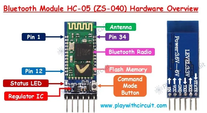
Antenna This antenna facilitates the transmission and reception of radio frequency (RF) signals, enabling wireless communication between Bluetooth devices.
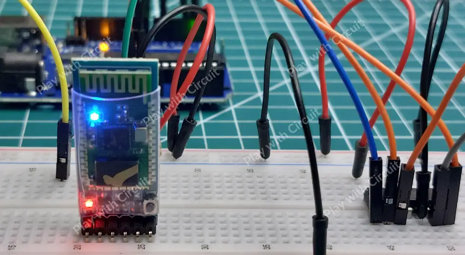
Status LED The red status LED blinks at various rates to indicate the module’s status.
- Upon powering up, the module enters Bluetooth pairing mode that is indicated by the LED flashing rapidly at approximately 2 Hz.
- When Bluetooth module is paired with a device, the LED flash pattern changes to two quick flashes followed by a pause, repeating this sequence.
- In AT mode or command mode, the LED blinks at a slow and steady rate.
Regulator IC It converts 5V at VCC pin to 3.3V.
HC-05 Pinout
HC-05 Bluetooth module has 6 pins. Let’s learn about the functionality of each pin.
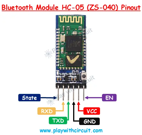
STATE This pin provides status information about the module’s connection state. It can be used to determine whether the module is in a connected or disconnected state. When this pin is HIGH it means the module is paired with another device else it remains LOW.
RXD This pin is used to receive data from external devices. It is typically connected to the TX (Transmit) pin of the device it communicates with.
❕Note
This pin is not 5V-tolerant. Hence, before connecting it to an external device make sure that the external device TX pin is a 3v3 volt pin else its TX signal must be stepped down to 3.3V.
TXD This pin transmits data from the HC-05 module to another device. It is connected to the RX (Receive) pin of the device it communicates with.
GND This pin is the ground connection and should be connected to the ground of the power supply.
VCC This is the power supply pin and is usually connected to a voltage source between 3.6V and 5V.
EN (Enable) Some HC-05 modules have an enable pin, which is used to control the module’s power state. This pin is usually HIGH (3.3V or 5V). When this pin is pulled LOW the module is disabled.
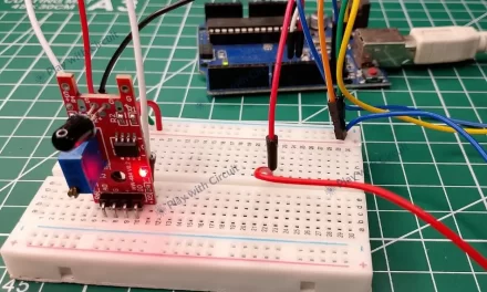
Basic Communication of HC-05 with Android Phone
Now we have a complete understanding of HC-05 module, let’s interface it with an Arduino UNO and communicate with Android Phone. To communicate with Android phone the Bluetooth module should run in Data mode and in by default configuration i.e. slave configuration. In this process we can also check if our module is working correctly or not. We will send data from Android phone to Arduino using Bluetooth module and vice-versa. First, let’s connect the HC-05 module to the Arduino Uno.
Hardware and Software Requirements
Hardware Requirement
| Component Name | Quantity | Remarks | Buy on Amazon.com | Buy on Amazon.in |
|---|---|---|---|---|
| Arduino UNO R3 | 1 | Revision R3 | Amazon | Amazon |
| HC-05 Bluetooth Module | 1 | It should have AT mode button and should have 6 pins. | Amazon | Amazon |
| Resistance | 2 | 1k and 2k | Amazon | Amazon |
| Breadboard | 1 | Full size | Amazon | Amazon |
| USB Cable Type A to B | 1 | for programming Arduino UNO | Amazon | Amazon |
| Jumper Wire | multiple | For Breadboard and Arduino Connections | Amazon | Amazon |
| 12V Supply Adapter | 1 | For providing power to Arduino | Amazon | Amazon |
Software Requirement
- Arduino IDE, Version 2.1.1 or above installed on your PC
- SoftwareSerial Library by Arduino.
Wiring a HC-05 Module to an Arduino
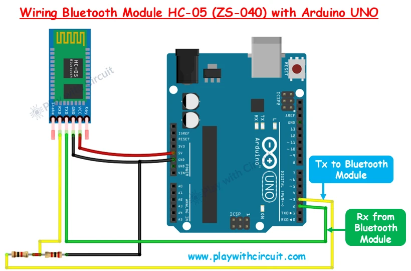
The Bluetooth module has a serial UART interface and we only have one serial interface which is used to download code in the Arduino Hence we will make pin 2 and pin 3 of Arduino as Rx and Tx pin for communication with the module.
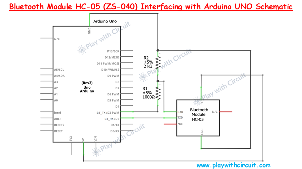
As the Rx pin of the module is not 5V tolerant, a voltage divider circuit is implemented using a 1 k and 2 K resistor to ensure the voltage at the Rx pin of the Module is not greater than 3v3.
The VCC and GND pins of the module are connected to the 5V pin and GND pin of the Arduino.
To make a voltage divider, a 1k and 2k resistor are connected in series, the free end of the 1k resistor is connected to pin 3 of Arduino, and the free and 2k resistor is connected to GND. The RXD of the module is connected to the junction of 1k and 2k resistors. Pin 2 of the Arduino is connected to the TXD pin of the module.
Refer to the below schematics for more details:
Arduino Code
This code is used to establish communication between an Arduino and an HC-05 Bluetooth module using software serial communication.
/*
Interfacing HC-05 (ZS-040) Bluetooth Module with Arduino UNO using pin 2(Rx) and 3(Tx)
by www.playwithcircuit.com
*/
// Include Software Serial Library this library makes DIO pins as Serial Pins
#include <SoftwareSerial.h>
//Create software serial object to communicate with HC-05
SoftwareSerial BTSerial(2, 3); // Now pin 2 and pin 3 of Arduino are Serial Rx & Tx pin Respectively
void setup() {
//Begin serial communication with Arduino and Arduino IDE (Serial Monitor)
Serial.begin(9600);
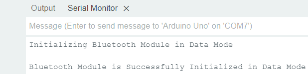
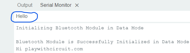
Serial.println("Initializing Bluetooth Module in Data Mode\n");
// Begin the soft Serial port and set the data rate for the SoftwareSerial port at 9600 to communicate with Bluetooth Module in Data Mode
BTSerial.begin(9600);
Serial.print("Bluetooth Module is Successfully Initialized in Data Mode\n");
}
void loop() {
// Get Data From Serial Terminal and Push to HC-05
if (Serial.available()) {
BTSerial.write(Serial.read());
}
// Get Data from HC-05 and push to Serial Monitor
if (BTSerial.available()) {
Serial.write(BTSerial.read());
}
}Code Description
First, we include the SoftwareSerial library, which allows to create serial communication ports on any digital pin of the Arduino board.
// Include Soft Serial Library this library makes DIO pins as Serial Pins
#include <SoftwareSerial.h>
Now we create a SoftwareSerial object named BTSerial, using pins 2 and 3 of the Arduino as the RX (receive) and TX (transmit) pins, respectively. This sets up a software serial port to communicate with the HC-05 Bluetooth module.
//Create software serial object to communicate with HC-05
SoftwareSerial BTSerial(2, 3);  // Now pin 2 and pin 3 of Arduino are Serial Rx & Tx pin Respectively
The setup() function begins with initializing the hardware serial communication at a baud rate of 9600 bps (bits per second).
Then a message is displayed on the Serial Monitor indicating that the Bluetooth module is being initialized in data mode.
This initializes the software serial communication with the HC-05 Bluetooth module at a baud rate of 9600 bps.
Then a confirmation message is displayed on the Serial Monitor indicating that the Bluetooth module has been successfully initialized in data mode.
void setup() {
  //Begin serial communication with Arduino and Arduino IDE (Serial Monitor)
  Serial.begin(9600);

  Serial.println("Initializing Bluetooth Module in Data Mode\n");

  // Begin the soft Serial port and set the data rate for the SoftwareSerial port at 9600 to communicate with Bluetooth Module in Data Mode
  BTSerial.begin(9600);

  Serial.print("Bluetooth Module is Successfully Initialized in Data Mode\n");
}
The first part of the loop() function checks if there is any data available to read from the hardware serial port (connected to the Serial Monitor). If data is available, it reads the data using Serial.read() and writes it to the HC-05 module using BTSerial.write(). This sends data from the Serial Monitor to the Bluetooth module.
The second part of the loop() checks if there is any data available to read from the software serial port (connected to the HC-05 module). If data is available, it reads the data using BTSerial.read() and writes it to the hardware serial port using Serial.write(). This sends data from the Bluetooth module to the Serial Monitor.
void loop() {
  // Get Data From Serial Terminal and Push to HC-05
  if (Serial.available()) {
    BTSerial.write(Serial.read());
  }

  // Get Data From HC-05 and push to Serial Monitor
  if (BTSerial.available()) {
    Serial.write(BTSerial.read());
  }
}
Output
Once the code is uploaded on the Arduino, open the serial monitor. You will see the following output at Arduino’s Serial Monitor window at baud-rate:
Connecting to the Android Phone
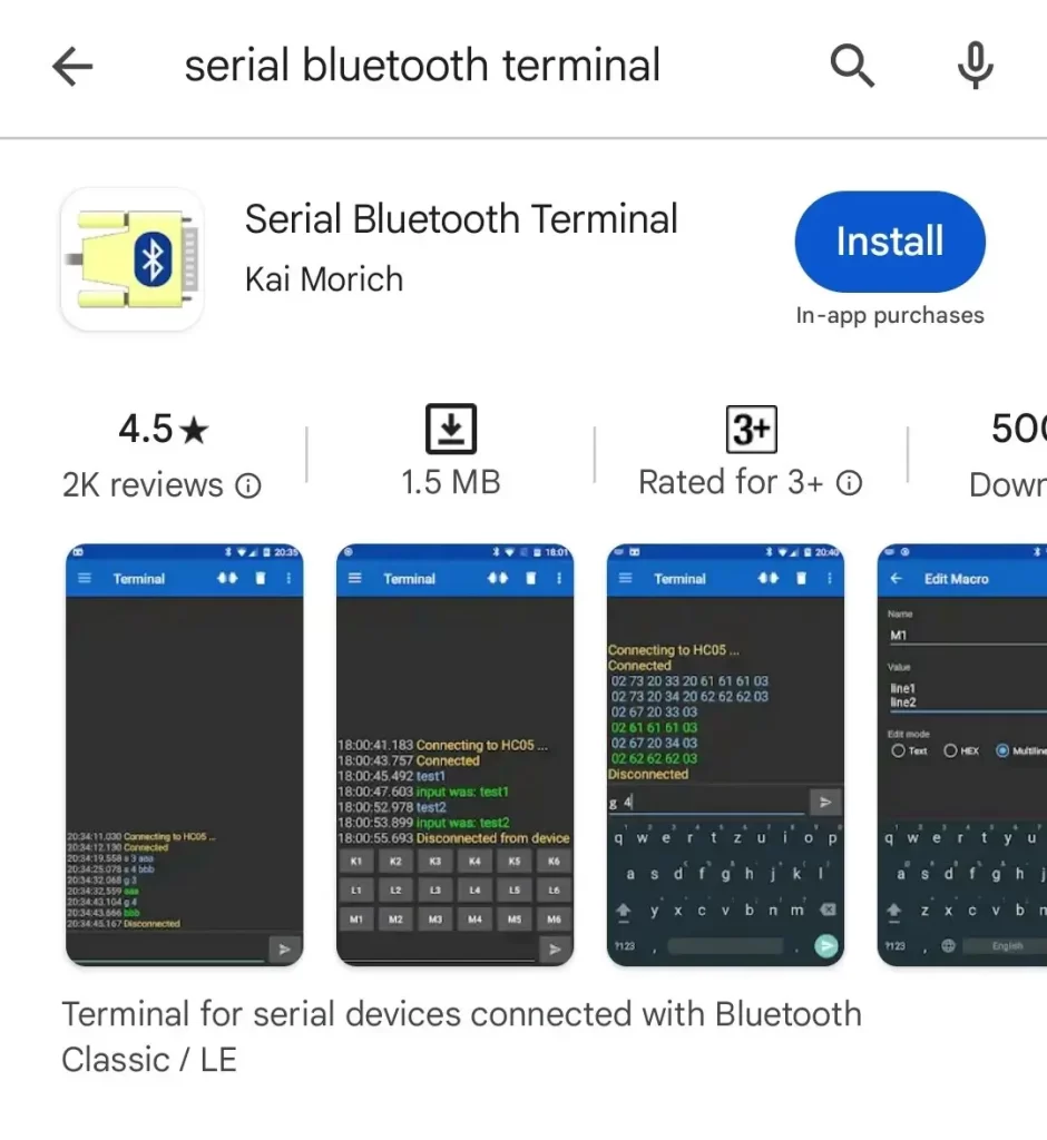
Step 1 Go to Play Store and search for Serial Bluetooth Terminal Application. Now Install the application in mobile.
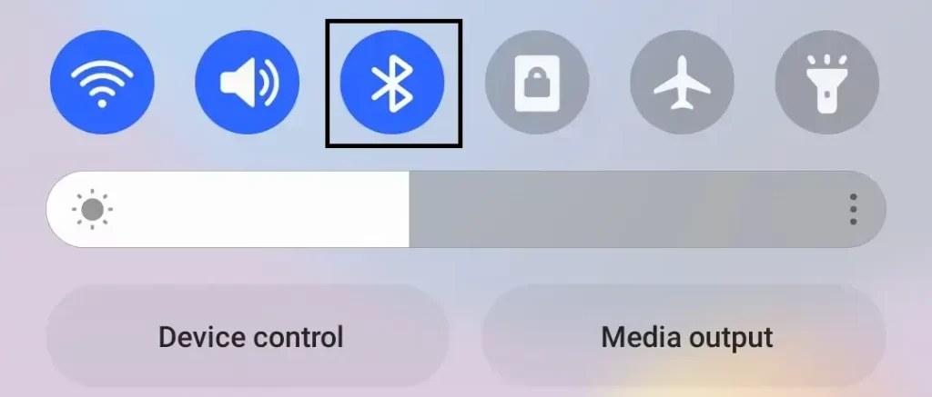
Step 2While the application is being downloaded in background, turn ON the Bluetooth in mobile.
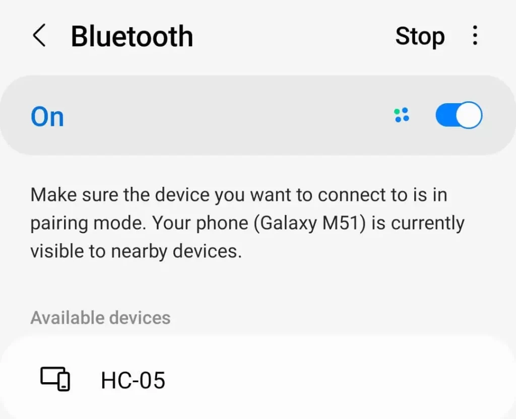
Step 3Search for HC-05 device, in Available devices. It is shown along with its Address, if it is not shown then make sure the module is powered up and its LED is blinking.
Now tap on the device name for pairing.
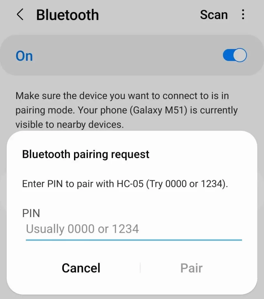
Step 4Enter password “1234”, if it doesn’t work then enter “0000”.
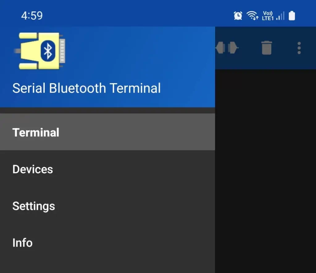
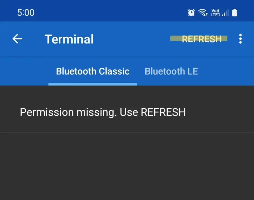
Step 5Open the Serial Bluetooth Terminal App and press the highlighted button with three parallel lines, just before Terminal is written.

Step 6Tap on the Devices menu item.
Step 7Tap on the Highlighted Refresh Button.
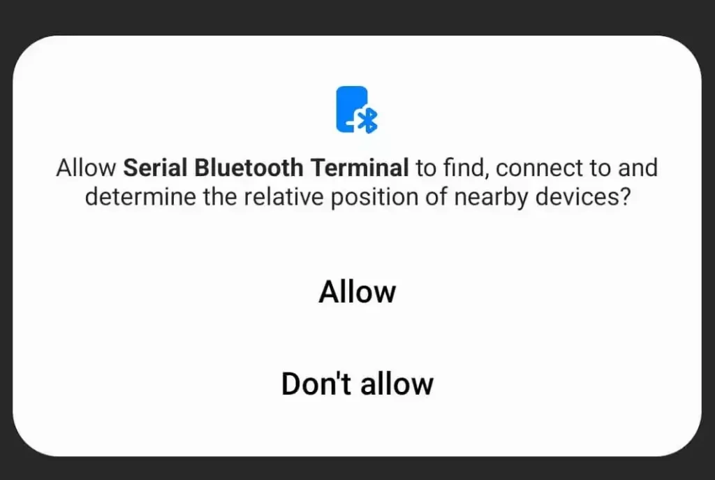
Step 8Tap on Allow.
Step 9Newly paired HC-05 Device will be shown in here. Now tap on the name.
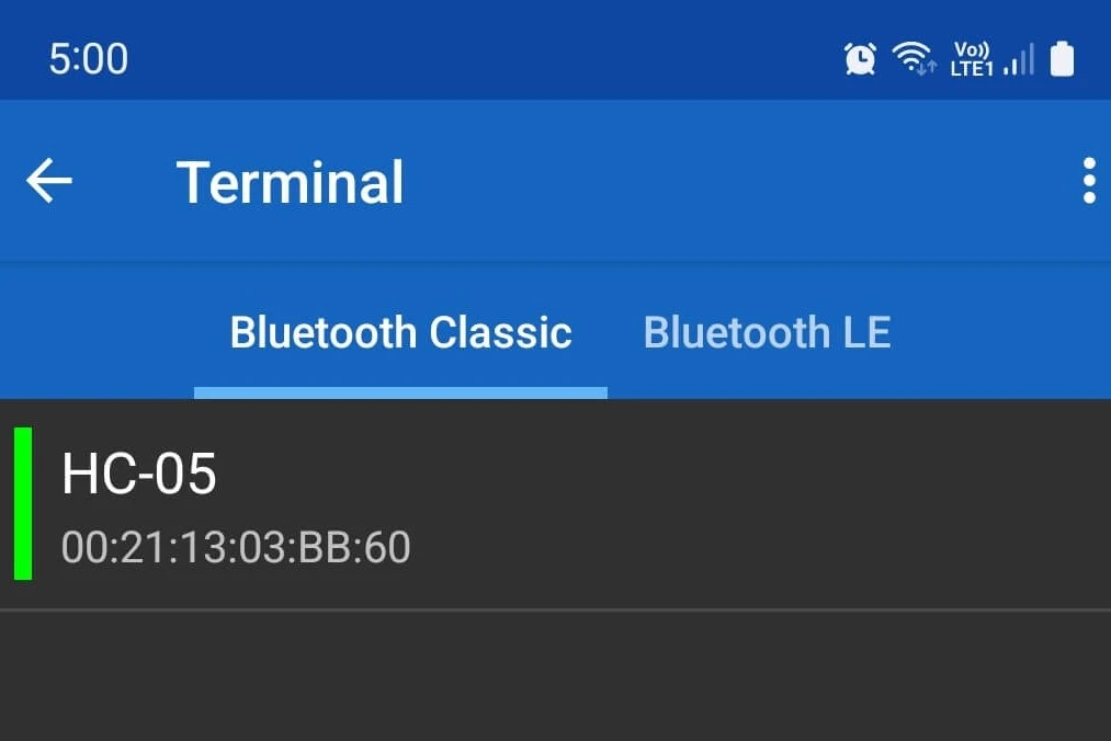
Step 10Now application is connected to the Bluetooth device. If it is not connected then the symbol on the top right of the image shall be open. Tap on that to reconnect/disconnect.
Now type your message and send it.

Step 11The message sent above will be seen on the Serial Terminal of Arduino IDE.
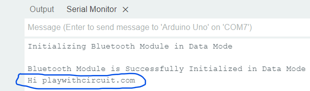
Step 12Now send message from Serial Terminal in Arduino IDE
Step 13The message from the Arduino Serial Terminal is shown in Serial Bluetooth Terminal Mobile Application in Green Colour.

Controlling 12V DC Fan Speed and Direction from Android Application using HC-05
Here, we will be controlling a 12V DC Fan using our own custom-made Android App, the link to the application is given at the end of this article.
Hardware and Software Requirements
Hardware Requirement
| Component Name | Quantity | Remarks | Buy on Amazon.com | Buy on Amazon.in |
|---|---|---|---|---|
| Arduino UNO R3 | 1 | Revision R3 | Amazon | Amazon |
| HC-05 Bluetooth Module | 1 | It should have AT mode button and should have 6 pins. | Amazon | Amazon |
| Resistance | 2 | 1k and 2k | Amazon | Amazon |
| L293D | 1 | Motor Driver IC | Amazon | Amazon |
| Breadboard | 1 | Full size | Amazon | Amazon |
| USB Cable Type A to B | 1 | for programming Arduino UNO | Amazon | Amazon |
| Jumper Wires | multiple | For Breadboard and Arduino Connections | Amazon | Amazon |
| 12V Supply Adapter | 2 | For providing power to Arduino and For providing supply to L293d Motor Driver IC | Amazon | Amazon |
| DC Fan | 1 | 12 V DC FAN | Amazon | Amazon |
Software Requirement
- Arduino IDE, Version 2.1.1 or above installed on your PC
- SoftwareSerial Library by Arduino.
Wiring Diagram
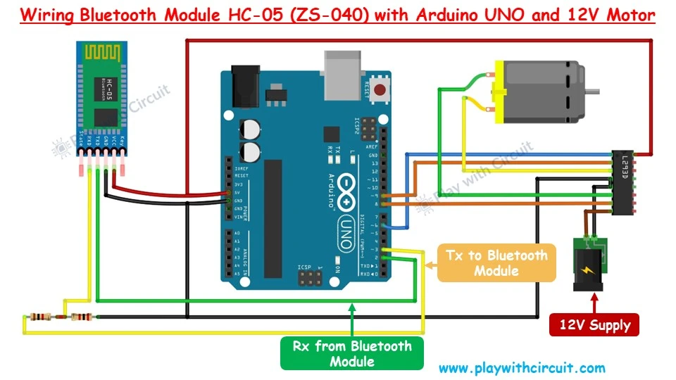
As described above the Bluetooth module has a serial UART interface and we only have one serial interface which is used to download, hence we will make pin 2 and pin 3 of Arduino as RX and TX pin for communication with the Bluetooth Module.
Here we are using L293D IC which controls the 12V DC fan. Another 12 V supply is required for the L293D IC to provide power to the motor of the fan.
❕Note
Arduino and fan should use separate 12V supply because as the speed of the fan increases it could draw more current which leads to a lack of current supplied to Arduino and Bluetooth module. As a result, the problem of frequent disconnection of Bluetooth from the Android app can occur. Hence it is advisable to use separate power supplies also the ground of the two power supplies should be connected.
Refer below schematics for more details:
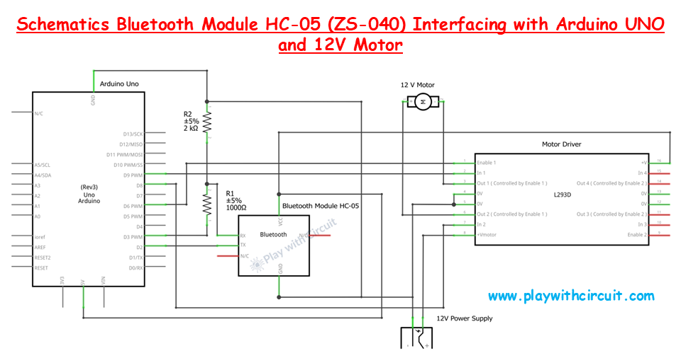
Connect Pin 14 of the L293D with VCC and pins 4 and 5 with the GND pin of the Arduino.
PWM pin 6 of the Arduino is connected with pin 1 which is the Enable pin of the L293D IC.
The 12V DC motor fan is connected to pins 3 and 6 of the L293D motor driver IC.
Pin 8 and 9 of the Arduino is connected to the input pin 2 and input pin 1 of the L293D IC.
The positive terminal of the 12 V power supply for the DC fan is connected to pin 8 of the Driver IC and the negative terminal is connected to GND pins 4 and 5.
Arduino Code
The following code allows for wireless control of a motor using an Android app to send commands via Bluetooth. The motor can be controlled to run clockwise, anticlockwise, or stop based on the received commands.
/*
Interfacing HC-05 (ZS-040) Bluetooth Module with Arduino UNO using pin 2(Rx) and 3(Tx) and Contol the Fan connected to Motor Using Android App by www.playwithcircuit.com
*/

// Include Soft Serial Library this library makes DIO pins as Serial Pins
#include <SoftwareSerial.h>
//Create software serial object to communicate with HC-05
SoftwareSerial BTSerial(2, 3);  // Now pin 2 and pin 3 of Arduino are Serial Rx & Tx pin Respectively

// Define MACROS related to communication with Android app
#define START_CHAR '*'
#define END_CHAR '#'
#define MAX_BUFFFER 14
#define MAX_INDEX 2

#define MOTOR_DIRECTION_INDEX 0
#define MOTOR_SPEED_INDEX     1

// Define the pins connected to the L293D IC
#define MOTOR_EN  6  // Enable pin for Motor A
#define MOTOR_IN1 9  // Input 1 for Motor A
#define MOTOR_IN2 8  // Input 2 for Motor A

// Declare variables related to communication with Android app
char serialInput;
int dataIndex = 0;
char databuffer[MAX_BUFFFER] = { 0 };
char cmdbuffer[MAX_BUFFFER] = { 0 };
bool dataRcvd = false;  // whether the string receiving is completed.

char char_array[MAX_INDEX][4] = { 0 };
int int_array[MAX_INDEX] = { 0 };

int index;
int cmdsize = 0;
bool bo_cmd_ok = false;
int row = 0;
int row_index = 0;

// Declare variable related to motor control
int motorSpeed = 0;
char previous_direction = 0;  // to store previous direction
bool one_time_flag = true;

int AsciitoInt(char* char_array);
void flushBTRcv();

void setup() {
  // Initialize motor control pins as outputs
  pinMode(MOTOR_EN, OUTPUT);
  pinMode(MOTOR_IN1, OUTPUT);
  pinMode(MOTOR_IN2, OUTPUT);
  // Begin the soft Serial port and set the data rate for the SoftwareSerial port at 9600 to communicate with Bluetooth Module in Data Mode
  BTSerial.begin(9600);
  // Set initial motor speed to zero
  analogWrite(MOTOR_EN, 0);
}

void loop() {
  // Get Data From HC-05
  while (BTSerial.available()) {
    // get the new byte
    serialInput = BTSerial.read();
    databuffer[dataIndex++] = serialInput;
    // if the incoming character is a END_CHAR character, set a flag so the main loop can do something about it
    if ((serialInput == END_CHAR) || (dataIndex == MAX_BUFFFER)) {
      dataIndex = 0;
      dataRcvd = true;
      flushBTRcv();
    }
  }

  if (dataRcvd == true) {
    cmdsize = 0;
    // Check for start and end character
    memset(cmdbuffer, 0x00, sizeof(cmdbuffer));

    // Extract command from RAW data sent
    for (int i = 0; i < MAX_BUFFFER; i++) {
      if (databuffer[i] == START_CHAR) {
        for (int j = 0; j < MAX_BUFFFER; j++) {
          cmdbuffer[j] = databuffer[j + i];
          cmdsize++;
          if (cmdbuffer[j] == END_CHAR) {
            bo_cmd_ok = true;
            break;
          }
        }
      }
      if (bo_cmd_ok == true) {
        break;
      }
    }
    dataRcvd = false;
    memset(databuffer, 0x00, sizeof(databuffer));
  }

  // if commmand is successfully extracted from data buffer and saved in command buffer
  if (bo_cmd_ok == true) {
    // Reset all variables and array
    index = 0;
    row = 0;
    row_index = 0;
    bo_cmd_ok = false;
    memset(char_array, 0x00, sizeof(char_array));
    memset(int_array, 0x00, sizeof(int_array));

    // as index 0 is the start character hence it is incremented by 1
    index++;

    // save two diffrent command in character array one is motor status and another is motor speed
    for (; index < cmdsize; index++) {
      if (cmdbuffer[index] == ',' || cmdbuffer[index] == '#') {
        row++;
        row_index = 0;
        continue;
      } else {
        char_array[row][row_index++] = cmdbuffer[index];
      }
    }

    for (int i = 0; i < MAX_INDEX; i++) {
      int_array[i] = AsciitoInt(&char_array[i][0]);
    }

    // Fan Motor Control
    if (int_array[MOTOR_DIRECTION_INDEX] == 1) {         // Clock-Wise case
      // this is done when suddendly direction cahnges then due to inertion it should not break
      if(previous_direction == 2)
      {
        digitalWrite(MOTOR_IN1, LOW);
        digitalWrite(MOTOR_IN2, LOW);
        analogWrite(MOTOR_EN, 0);
        delay(3000);
      }
      motorSpeed = map(int_array[MOTOR_SPEED_INDEX],340,3,211,255);
      // If speed value is less than 211 or more than 255 set it to 211
      if(motorSpeed < 211 || motorSpeed > 255){
        motorSpeed = 211;
      }
      digitalWrite(MOTOR_IN1, HIGH);
      digitalWrite(MOTOR_IN2, LOW);
      analogWrite(MOTOR_EN, motorSpeed);
      one_time_flag = true;
    } else if (int_array[MOTOR_DIRECTION_INDEX] == 2) {  // Anti Clock-Wise case
      // this is done when suddendly direction cahnges then due to inertion it should not break
      if(previous_direction == 1)
      {
        digitalWrite(MOTOR_IN1, LOW);
        digitalWrite(MOTOR_IN2, LOW);
        analogWrite(MOTOR_EN, 0);
        delay(3000);
      }
      motorSpeed = map(int_array[MOTOR_SPEED_INDEX],340,3,211,255);
      // If speed value is less than 211 or more than 255 set it to 211
      if(motorSpeed < 211 || motorSpeed > 255){
        motorSpeed = 211;
      }
      digitalWrite(MOTOR_IN1, LOW);
      digitalWrite(MOTOR_IN2, HIGH);
      analogWrite(MOTOR_EN, motorSpeed);
      one_time_flag = true;
    } else if (int_array[MOTOR_DIRECTION_INDEX] == 0) {   // Stop case
      digitalWrite(MOTOR_IN1, LOW);
      digitalWrite(MOTOR_IN2, LOW);
      analogWrite(MOTOR_EN, 0);
      if (one_time_flag == true){
        delay(3000);
        one_time_flag = false;
      }
    }
    else{
        // do nothing in case of wrong value
    }
    previous_direction = int_array[MOTOR_DIRECTION_INDEX];
  }
}

// Convert Ascii character received into integera
int AsciitoInt(char* char_array) {
  int ret_val = 0;
  int arra_len = strlen(char_array);
  for (int i = 0; i < arra_len; i++) {
    ret_val += (char_array[i] - 0x30);
    ret_val *= 10;
  }
  return (ret_val / 10);
}

// Flush Extra chracter from BT Rx buffer
void flushBTRcv() {
  char ret_char;
  while (BTSerial.available() > 0) {
    ret_char = BTSerial.read();
  }
}
Code Explanation
First we include the SoftwareSerial library and create a SoftwareSerial object named BTSerial using pins 2 and 3 of the Arduino as the RX (receive) and TX (transmit) pins, respectively.
// Include Soft Serial Library this library makes DIO pins as Serial Pins
#include <SoftwareSerial.h>
//Create software serial object to communicate with HC-05
SoftwareSerial BTSerial(2, 3);  // Now pin 2 and pin 3 of Arduino are Serial Rx & Tx pin Respectively
Now, we define macros for special characters, buffer sizes, indices, and motor control pins. The motor control pins are connected to the L293D motor driver IC.
// Define MACROS related to communication with Android app
#define START_CHAR '*'
#define END_CHAR '#'
#define MAX_BUFFFER 14
#define MAX_INDEX 2
#define MOTOR_DIRECTION_INDEX 0
#define MOTOR_SPEED_INDEX     1
// Define the pins connected to the L293D IC
#define MOTOR_EN  6  // Enable pin for Motor A
#define MOTOR_IN1 9  // Input 1 for Motor A
#define MOTOR_IN2 8  // Input 2 for Motor A
Then we define variables that are used for communication with the Bluetooth module and for motor control. databuffer and cmdbuffer are used to store incoming data, while char_array and int_array store processed commands. motorSpeed and previous_direction are used to control the motor.
// Declare variables related to communication with Android app
char serialInput;
int dataIndex = 0;
char databuffer[MAX_BUFFFER] = { 0 };
char cmdbuffer[MAX_BUFFFER] = { 0 };
bool dataRcvd = false;  // whether the string receiving is completed.

char char_array[MAX_INDEX][4] = { 0 };
int int_array[MAX_INDEX] = { 0 };

int index;
int cmdsize = 0;
bool bo_cmd_ok = false;
int row = 0;
int row_index = 0;

// Declare variable related to motor control
int motorSpeed = 0;
char previous_direction = 0;  // to store previous direction
bool one_time_flag = true;

int AsciitoInt(char* char_array);
void flushBTRcv();
In the setup() function:
- The motor control pins are set as outputs.
- Serial communication is initialized for software serial ports at 9600 baud.
- The motor speed is initially set to zero.
void setup() {
  // Initialize motor control pins as outputs
  pinMode(MOTOR_EN, OUTPUT);
  pinMode(MOTOR_IN1, OUTPUT);
  pinMode(MOTOR_IN2, OUTPUT);
  // Begin the soft Serial port and set the data rate for the SoftwareSerial port at 9600 to communicate with Bluetooth Module in Data Mode
  BTSerial.begin(9600);
  // Set initial motor speed to zero
  analogWrite(MOTOR_EN, 0);
}
In the loop() function,
- Data is read from the Bluetooth module, stored it in databuffer, and sets dataRcvd to true when a complete message is received.
- Then the received data is processed to extract commands and save them in cmdbuffer.
- If a command is successfully extracted, it is parsed and saved in char_array.
- The parsed values are converted to integers and stored in int_array.
Based on the parsed commands:
- If the motor direction is set to 1 (clockwise), the motor speed is set and the motor runs in the clockwise direction.
- If the motor direction is set to 2 (anticlockwise), the motor speed is set and the motor runs in the anticlockwise direction.
- If the motor direction is set to 0 (stop), the motor stops.
void loop() {
  // Get Data From HC-05
  while (BTSerial.available()) {
    // get the new byte
    serialInput = BTSerial.read();
    databuffer[dataIndex++] = serialInput;
    // if the incoming character is a END_CHAR character , set a flag so the main loop can do something about it
    if ((serialInput == END_CHAR) || (dataIndex == MAX_BUFFFER)) {
      dataIndex = 0;
      dataRcvd = true;
      flushBTRcv();
    }
  }

  if (dataRcvd == true) {
    cmdsize = 0;
    // Check for start and end character
    memset(cmdbuffer, 0x00, sizeof(cmdbuffer));

    // Extract command from RAW data sent
    for (int i = 0; i < MAX_BUFFFER; i++) {
      if (databuffer[i] == START_CHAR) {
        for (int j = 0; j < MAX_BUFFFER; j++) {
          cmdbuffer[j] = databuffer[j + i];
          cmdsize++;
          if (cmdbuffer[j] == END_CHAR) {
            bo_cmd_ok = true;
            break;
          }
        }
      }
      if (bo_cmd_ok == true) {
        break;
      }
    }
    dataRcvd = false;
    memset(databuffer, 0x00, sizeof(databuffer));
  }

  // if commmand is successfully extracted from data buffer and saved in command buffer
  if (bo_cmd_ok == true) {
    // Reset all variables and array
    index = 0;
    row = 0;
    row_index = 0;
    bo_cmd_ok = false;
    memset(char_array, 0x00, sizeof(char_array));
    memset(int_array, 0x00, sizeof(int_array));

    // as index 0 is the start character hence it is incremented by 1
    index++;

    // save two diffrent command in character array one is motor status and another is motor speed
    for (; index < cmdsize; index++) {
      if (cmdbuffer[index] == ',' || cmdbuffer[index] == '#') {
        row++;
        row_index = 0;
        continue;
      } else {
        char_array[row][row_index++] = cmdbuffer[index];
      }
    }

    for (int i = 0; i < MAX_INDEX; i++) {
      int_array[i] = AsciitoInt(&char_array[i][0]);
    }

    // Fan Motor Control
    if (int_array[MOTOR_DIRECTION_INDEX] == 1) {         // Clock-Wise case
      // this is done when suddendly direction cahnges then due to inertion it should not break
      if(previous_direction == 2)
      {
        digitalWrite(MOTOR_IN1, LOW);
        digitalWrite(MOTOR_IN2, LOW);
        analogWrite(MOTOR_EN, 0);
        delay(3000);
      }
      motorSpeed = map(int_array[MOTOR_SPEED_INDEX],340,3,211,255);
      // If speed value is less than 211 or more than 255 set it to 211
      if(motorSpeed < 211 || motorSpeed > 255){
        motorSpeed = 211;
      }
      digitalWrite(MOTOR_IN1, HIGH);
      digitalWrite(MOTOR_IN2, LOW);
      analogWrite(MOTOR_EN, motorSpeed);
      one_time_flag = true;
    } else if (int_array[MOTOR_DIRECTION_INDEX] == 2) {  // Anti Clock-Wise case
      // this is done when suddendly direction cahnges then due to inertion it should not break
      if(previous_direction == 1)
      {
        digitalWrite(MOTOR_IN1, LOW);
        digitalWrite(MOTOR_IN2, LOW);
        analogWrite(MOTOR_EN, 0);
        delay(3000);
      }
      motorSpeed = map(int_array[MOTOR_SPEED_INDEX],340,3,211,255);
      // If speed value is less than 211 or more than 255 set it to 211
      if(motorSpeed < 211 || motorSpeed > 255){
        motorSpeed = 211;
      }
      digitalWrite(MOTOR_IN1, LOW);
      digitalWrite(MOTOR_IN2, HIGH);
      analogWrite(MOTOR_EN, motorSpeed);
      one_time_flag = true;
    } else if (int_array[MOTOR_DIRECTION_INDEX] == 0) {   // Stop case
      digitalWrite(MOTOR_IN1, LOW);
      digitalWrite(MOTOR_IN2, LOW);
      analogWrite(MOTOR_EN, 0);
      if (one_time_flag == true){
        delay(3000);
        one_time_flag = false;
      }
    }
    else{
        // do nothing in case of wrong value
    }
    previous_direction = int_array[MOTOR_DIRECTION_INDEX];
  }
}

// Convert Ascii character received into integera
int AsciitoInt(char* char_array) {
  int ret_val = 0;
  int arra_len = strlen(char_array);
  for (int i = 0; i < arra_len; i++) {
    ret_val += (char_array[i] - 0x30);
    ret_val *= 10;
  }
  return (ret_val / 10);
}

// Flush Extra chracter from BT Rx buffer
void flushBTRcv() {
  char ret_char;
  while (BTSerial.available() > 0) {
    ret_char = BTSerial.read();
  }
}
Download Android Application
Project Demonstration
Exploring Further
Now that you understand HC-05 Bluetooth module and how to send and receive data between the module and your smartphone, it’s time to dive deeper. Next, you can explore configuring the HC-05 using AT commands and establish a wireless communication between two Arduino Boards.
Wireless Communication between two Arduino Boards using HC-05 Bluetooth Modules
In this Arduino tutorial, we will learn how to pair two HC-05 Bluetooth modules and configure them as Master and Slave Via AT Command.
