Fire incidents can be devastating. To prevent such incidents, it is critical to detect them early. There are various methods for fire detection, such as identifying temperature changes or detecting smoke. But these methods have limitations, smoke detectors may fail to identify fires that produce little or no smoke, while temperature-based systems often respond only after a significant rise in heat, leaving little room for timely action.
To overcome these shortcomings, thermal radiation detection is a more reliable method. The simple and cost-effective way to detect thermal radiation is to use a flame sensor.
This tutorial will guide you through interfacing a flame sensor module with an Arduino. We will create a basic fire detection system that senses the presence of a flame and alerts the surroundings with an alarm.
How does the Flame Sensor Module Work?
The working of the flame sensor is very simple. The module detects infrared light emitted by hot objects. A flame or fire emits a significant amount of IR radiation, which is captured by the photodiode present in the sensor module. The LM393 comparator IC then compares the photodiode’s output with a predefined threshold set by a potentiometer on the module. When the detected IR radiation surpasses this threshold, the Digital output (DO) of the module changes its state, signalling the presence of a flame.
The Analog output (AO) can also be used to detect the intensity of the IR radiation. The onboard Signal LED turns ON to indicate the detection of fire, providing a visual indication. The sensitivity of the flame sensor can be adjusted using the potentiometer.
Flame Sensor Module Specifications
- Operating Voltage: Typically 3.3V to 5V, making it compatible with most microcontrollers.
- Detection Angle: Usually around 60°, providing a focused sensing area.
- Detection Range: Can detect flames within 1 to 2 meters.
- Adjustable Sensitivity: Equipped with a potentiometer to fine-tune the sensitivity.
- Small Form Factor: Compact size for easy integration into projects.
Flame Sensor Module Hardware Overview
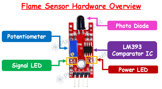
Photodiode The core component that detects the infrared light emitted by flames.
Comparator IC (LM393) Processes the signal from the infrared sensor and converts it into a digital signal. The IC ensures accurate detection by comparing the received signal with a predefined threshold.
Potentiometer It has a pot to adjust the sensitivity of the module, ensuring it works optimally in different environments.
Power LED This LED turns ON when the module is powered.
Signal LED This LED will turn OFF, when a flame is detected.
Flame Sensor Module Pinout
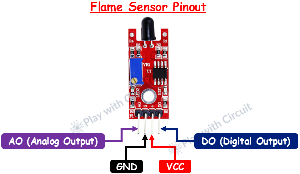
The flame sensor module has 4 pins:
VCC This pin provides power to the module.
GND This is the Ground pin connected to the Ground pin of the Arduino.
DO (Digital Output) Provides a digital signal (HIGH or LOW) depending on the presence of a flame.
AO (Analog Output) Outputs an analog signal proportional to the flame’s intensity.
Calibration of Flame Sensor using Arduino UNO
Before using the flame sensor in any Digital output mode, it is important to calibrate the sensor with the help of Arduino Uno. After calibration we will build a fire detection system with Arduino using Digital/Analog output of the flame sensor.
For Analog mode we just need the counts from the Analog input when flame is present. No potentiometer setting will be required.
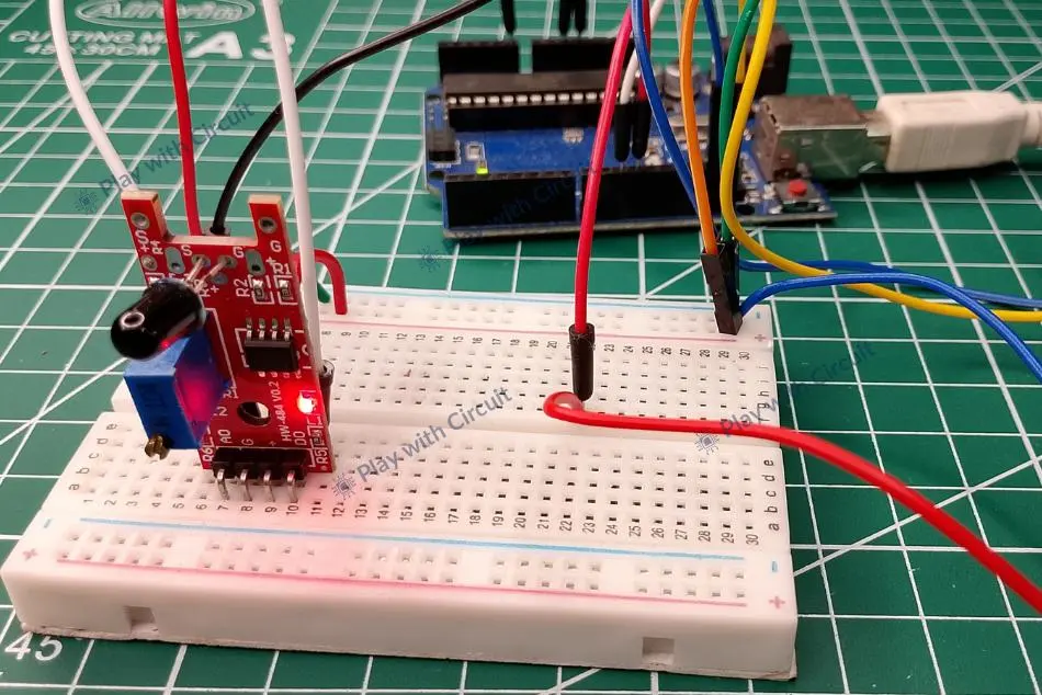
For calibration we need one flame sensor, Arduino UNO, I2C LCD, breadboard few wires and flame source. Before calibration let’s connect the flame sensor with the Arduino using the following wiring diagram.
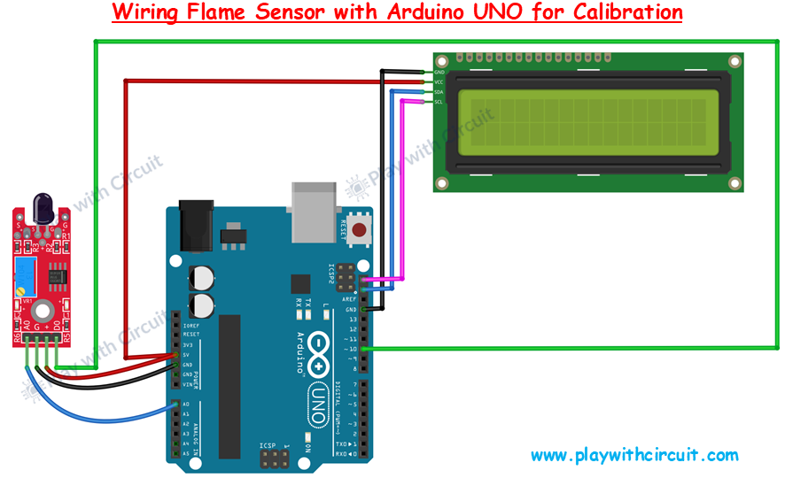
Connect the Vcc and GND pin of the flame sensor with Vcc and GND pin of Arduino.
Connect Analog output pin Ao of the flame sensor with the Analog input pin A0 of Arduino and Digital Output pin of flame sensor with pin 10 of the Arduino.
The I2C LCD used here will display Analog Counts and state of Digital Output of the flame sensor. Connect the Vcc and GND pin of I2C LCD with Vcc and GND pin of Arduino. SCL(clock) and SDA(data) pins of I2C LCD are connected to SCL and SDA pins of Arduino. SCL and SDA pins are the same as pins A5 and A4 Analog input pins of Arduino where pink and blue wires are connected with LCD. These header pins are also connected to A5 and A4 pins of Arduino.
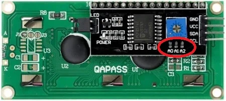
Hence while using the I2C peripheral of Arduino, do not use Analog input functionality at pin A4 or A5 pin. Make sure A0, A1, A2 address jumpers are not shorted when using I2C LCD. As in code we will be using Address 0x27 for the I2C LCD which will only be formed when these jumpers are not shorted in the I2C LCD. When all of these pins are shorted the address will become 0x20.
Arduino Code for Calibration of Flame Sensor
The following code interfaces flame sensor with Arduino UNO and displays its analog output on an I2C LCD. This sketch is used for the calibration of the flame sensor using blue colored trim pot present on flame sensor.
/*
Interfacing flame Sensor with Arduino UNO using Analog input pin of Arduino and displaying the Analog counts on the I2C LCD.
Code by www.playwithcircuit.com
*/

#include <LiquidCrystal_I2C.h>  // Library to Run I2C LCD

// define the size of filter array
#define FILTER_SIZE 30

// Set the LCD address to 0x27 for a 16 chars and 2 line display
LiquidCrystal_I2C lcd(0x27, 16, 2);

// Define the analog input pin, for the flame sensor's analog output
const int FlameSensorAnalogPin = A0;

// Define the digital input pin, for the flame sensor's digital output
const int FlameSensorDigitalPin = 10;

// Variable to store the Analog count from flame sensor
int FlameCounts;
// Variable to store the filtered Analog count from flame sensor
int filteredFlameCounts;

// Analog value filter
int Filter(int sensorValue);

void setup() {
  // initialize the LCD
  lcd.init();
  // Turn ON the Backlight
  lcd.backlight();
  // Clear the display buffer
  lcd.clear();

  // Make digital pin of sensor as input
  pinMode(FlameSensorDigitalPin, INPUT);

  // Print a message to the LCD
  lcd.setCursor(0, 0);
  lcd.print("Initializing");

  // Print a message to the LCD
  lcd.setCursor(0, 1);
  lcd.print("Please Wait...");

  // flush out the first 100 values and give time to flame sensor counts to be stable
  for (int i = 0; i < 100; i++) {
    // Read the value from the flame sensor
    FlameCounts = analogRead(FlameSensorAnalogPin);
    // Filter the input counts
    filteredFlameCounts = Filter(FlameCounts);
    delay(10);
  }
  // Clear the display buffer
  lcd.clear();

  // Print a message to the LCD
  lcd.setCursor(0, 0);
  lcd.print("Ana. Cnts:      ");

  // Print a message to the LCD
  lcd.setCursor(0, 1);
  lcd.print("Dig. Oupt:      ");
}

void loop() {
  // Static variables to save the last flame sensor counts
  static int LastFlameCounts = 0xFFFF;

  // Read the value from the flame sensor
  FlameCounts = analogRead(FlameSensorAnalogPin);

  // Filter the input counts
  filteredFlameCounts = Filter(FlameCounts);

  // If current flame sensor counts is not equal to last saved counts
  if (LastFlameCounts != filteredFlameCounts) {

    // Print a message to the LCD
    lcd.setCursor(0, 0);
    lcd.print("Ana. Cnts: ");
    lcd.print(filteredFlameCounts);
    lcd.print(" ");

    // Print a message to the LCD
    lcd.setCursor(0, 1);
    lcd.print("Dig. Oupt: ");
    lcd.print(digitalRead(FlameSensorDigitalPin));
  }

  LastFlameCounts = filteredFlameCounts;
  // Wait for 10ms before the next loop
  delay(10);
}

// Averaging filter to filter Analog values
int Filter(int sensorValue) {
  static int analogArray[FILTER_SIZE] = { 0 };
  unsigned long int filteredValue = 0;
  int i;
  // Shift the element, removing the oldest value stored at index 0
  for (i = 0; i < (FILTER_SIZE - 1); i++) {
    analogArray[i] = analogArray[i + 1];
  }
  // Put the current value in the last element of Array i.e. at index FILTER_SIZE-1
  analogArray[FILTER_SIZE - 1] = sensorValue;
  for (i = 0; i < FILTER_SIZE; i++) {
    filteredValue += analogArray[i];
  }
  // Return Filtered Analog Value
  return (filteredValue / FILTER_SIZE);
}
Code Description
The sketch begins by including the LiquidCrystal_I2C library, which simplifies interfacing the LCD via the I2C protocol. Then we define a macro FILTER_SIZE for the number of samples to average in the analog signal filtering.
#include <LiquidCrystal_I2C.h>  // Library to Run I2C LCD

// define the size of filter array
#define FILTER_SIZE 30
Now we create an object named lcd with the I2C address 0x27, targeting a 16×2 character LCD.
Then we define the analog input pin A0 for flame sensor’s analog output and digital input pin 10 for digital output. We declare two integer variables: FlameCounts for storing raw analog sensor value and filteredFlameCounts for the filtered version of that value.
int Filter(int sensorValue) tells the compiler that a function named Filter exists, which takes an integer input (the sensor value) and returns a filtered integer output. Although the full function is defined later in the code.
// Set the LCD address to 0x27 for a 16 chars and 2 line display
LiquidCrystal_I2C lcd(0x27, 16, 2);

// Define the analog input pin, for the flame sensor's analog output
const int FlameSensorAnalogPin = A0;

// Define the digital input pin, for the flame sensor's digital output
const int FlameSensorDigitalPin = 10;

// Variable to store the Analog count from flame sensor
int FlameCounts;

// Variable to store the Filtered Analog count from flame sensor
int filteredFlameCounts;

// Analog value filter
int Filter(int sensorValue);
In the setup() function we initialize the LCD and turn ON its backlight. It clears any residual data on the screen and sets the flame sensor’s digital pin as an input. Then, we show a message (“Initializing / Please Wait…”) to notify the user that the system is booting and stabilizing sensor readings.
void setup() {
  // initialize the LCD
  lcd.init();
  // Turn on the Backlight
  lcd.backlight();
  // Clear the display buffer
  lcd.clear();

  // Make digital pin of sensor as input
  pinMode(FlameSensorDigitalPin, INPUT);

  // Print a message to the LCD
  lcd.setCursor(0, 0);
  lcd.print("Initializing");

  // Print a message to the LCD
  lcd.setCursor(0, 1);
  lcd.print("Please Wait...");
A for loop reads the sensor 100 times with a 10ms delay to let the readings stabilize. Each reading is passed through a filter function that computes an average, ensuring smoother values are displayed once the system starts operating.
After stabilization, the LCD is cleared again and prepared with labels: “Ana. Cnts:” on the first line and “Dig. Oupt:” on the second.
 // flush out the first 100 values and give time to flame sensor counts to be stable
  for (int i = 0; i < 100; i++) {
    // Read the value from the flame sensor
    FlameCounts = analogRead(FlameSensorAnalogPin);
    // Filter the input counts
    filteredFlameCounts = Filter(FlameCounts);
    delay(10);
  }
  // Clear the display buffer
  lcd.clear();

  // Print a message to the LCD
  lcd.setCursor(0, 0);
  lcd.print("Ana. Cnts:      ");

  // Print a message to the LCD
  lcd.setCursor(0, 1);
  lcd.print("Dig. Oupt:      ");
Inside loop(), the analog value is read continuously and filtered using the same filter function. A static variable LastFlameCounts holds the previous value to detect changes.
void loop() {
  // Static variables to save the last flame sensor counts
  static int LastFlameCounts = 0xFFFF;

  // Read the value from the flame sensor
  FlameCounts = analogRead(FlameSensorAnalogPin);

 // Filter the input counts
  filteredFlameCounts = Filter(FlameCounts);
If the current filtered value differs from the previous one, the LCD updates both analog and digital outputs. After updating the display, the new value is stored in LastFlameCounts, and a 10ms delay is introduced to reduce flickering.
 // If current flame sensor counts is not equal to last saved counts
  if (LastFlameCounts != filteredFlameCounts) {

    // Print a message to the LCD
    lcd.setCursor(0, 0);
    lcd.print("Ana. Cnts: ");
    lcd.print(filteredFlameCounts);
    lcd.print(" ");

    // Print a message to the LCD
    lcd.setCursor(0, 1);
    lcd.print("Dig. Oupt: ");
    lcd.print(digitalRead(FlameSensorDigitalPin));
  }

  LastFlameCounts = filteredFlameCounts;
  // Wait for 10ms before the next loop
  delay(10);
}
This function filters out noise from the analog signal using a simple moving average. It stores the last 30 sensor values in a static array and averages them.
To maintain the sliding window, older values are shifted to the left, and the latest reading is added at the end.
The function sums up all elements in the array and returns the average. This process smooths sudden spikes or drops in readings, providing more consistent output.
// Averaging filter to filter Analog values
int Filter(int sensorValue) {
  static int analogArray[FILTER_SIZE] = { 0 };
  unsigned long int filteredValue = 0;
  int i;
  // Shift the element removing the oldest value stored at index 0
  for (i = 0; i < (FILTER_SIZE - 1); i++) {
    analogArray[i] = analogArray[i + 1];
  }
  // Put the current value in the last element of Array i.e. at index FILTER_SIZE-1
  analogArray[FILTER_SIZE - 1] = sensorValue;
  for (i = 0; i < FILTER_SIZE; i++) {
    filteredValue += analogArray[i];
  }
  // Return Filtered Analog Value
  return (filteredValue / FILTER_SIZE);
}
Steps for Calibration
-
Upload the above code in Arduino and after proper wiring turn ON the circuit.
-
Check the Analog counts on the LCD, it could be either above 1000 or it could be near 0.
-
Since manufactures create their sensor differently hence there is no such standard that what could be the counts and Digital output may be 1 or may be 0. For the sensor used here the counts are above 1000 and digital output is 0.
-
Light up the flame source near the sensor and check the counts. The Analog counts should definitely change and Digital output may or may not change. It depends on the sensitivity adjustment of the POT.
-
Try to turn the POT in either direction and try to decrease the sensitivity of the sensor using POT. While doing so the sensitivity of the sensor should reach that point when the analog count and digital output should not change whether flame is present or not. Here it is achieved by rotating the POT in an anticlockwise direction.
-
Now light the flame in that distance from the sensor that you want to detect fire. In the starting the count could be at extremes but as you increase the sensitivity (by rotating the POT) of the sensor the counts start to change and at some point, the state of digital output changes, rotate the POT one more time so that sensitivity can be properly adjusted. Note down the Analog counts to be used later in another code. Make sure you rotate the POT in the opposite direction as you did in previous step (number 2) to decrease the sensitivity, for the sensor used here, we rotate it clockwise now.
-
Initially, for our flame sensor counts are above 1000 and digital output is LOW (0) . After adjusting the sensitivity of sensor the counts for detecting the flame becomes 300. At this point the Digital output is HIGH. So,
-
When there is no flame the Analog output of the sensor is HIGH and Digital output is LOW.
-
When flame is detected the voltage at Analog pin decreases and Digital output turns HIGH.
This behavior is specific to the sensor we are using here. Other sensors may work differently, so it’s important to calibrate your sensor in a similar way to understand its behaviour.
The fire detection system logic which we will be writing in further code will be based on the sensor behavior. So make sure to test and calibrate your sensor properly before using it in your project.
Arduino Project — Fire Detection System using Flame Sensor and Arduino
Here we will build a fire detection system using Arduino and flame sensor. In this system I2C LCD will display whether the fire is detected or not. If fire is detected a buzzer will start ringing for indication.
When the flame is gone the buzzer stops. To detect the flame we can use Analog pin as well as digital pin of flame sensor. So first we will detect the flame using Analog output of sensor and then we will use Digital output of sensor.
Hardware Requirement
| Component Name | Quantity | Remarks | Where to Buy |
|---|---|---|---|
| Arduino UNO R3 | 1 | Revision R3 | Amazon |
| Flame sensor | 1 | For detecting flame | Amazon |
| LCD 16x2 | 1 | I2C support | Amazon |
| Jumper Wires | 1 | For Arduino and Sensor connections | Amazon |
| Breadboard | 1 | Full size | Amazon |
| Buzzer | 1 | 5V | Amazon |
| USB Cable Type A to B | 1 | for programming Arduino UNO | Amazon |
| 12V Supply Adapter | 1 | For providing power to Arduino | Amazon |
Software Requirement
- Arduino IDE, Version 2.3.4 or above installed on your PC.
- LiquidCrystal_I2C Library by Frank de Brabander V 1.1.2
Wiring diagram when using Analog Output pin of Flame Sensor
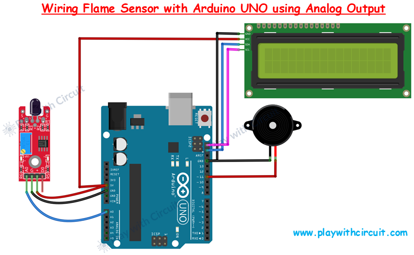
The wiring will be the same as above. The only difference is that here we are not using the digital output pin of the flame sensor. We have also added a buzzer whose red wire is connected at pin 11 of the and the black wire of buzzer is connected to GND of Arduino.
Arduino Code
The following Arduino sketch shows how to interface a flame sensor with an Arduino UNO using its analog output, and display the fire detection status on an I2C LCD. A buzzer is activated when fire is detected. To prevent false alarms due to noise or fluctuations in sensor readings, we use an averaging filter to smooth the analog values in code.
/*
Interfacing Flame Sensor with Arduino UNO using Analog input pin of Arduino and displaying fire detected on I2C LCD.
code by www.playwithcircuit.com
*/

#include <LiquidCrystal_I2C.h>  // Library to Run I2C LCD

// Buzzer pin
#define BUZZER_PIN 11
// Maximum counts to detect the flame
#define FLAME_DETECT_COUNTS 300
// define the size of filter array
#define FILTER_SIZE 30

// Set the LCD address to 0x27 for a 16 chars and 2 line display
LiquidCrystal_I2C lcd(0x27, 16, 2);

// Define the analog input pin, for the flame sensor's analog output
const int FlameSensorAnalogPin = A0;

// Variable to store the Analog count from flame sensor
int FlameCounts;
// Variable to store the Filtered Analog count from flame sensor
int filteredFlameCounts;

// Analog value filter
int Filter(int sensorValue);

void setup() {
  // initialize the LCD
  lcd.init();
  // Turn ON the Backlight
  lcd.backlight();
  // Clear the display buffer
  lcd.clear();

  // Make buzzer pin as output
  pinMode(BUZZER_PIN, OUTPUT);

  // Turn OFF buzzer pin
  digitalWrite(BUZZER_PIN, LOW);

  // Print a message to the LCD
  lcd.setCursor(0, 0);
  lcd.print("Initializing");

  // Print a message to the LCD
  lcd.setCursor(0, 1);
  lcd.print("Please Wait...");

  // flush out the first 100 values AND give time to flame sensor counts to be stable
  for (int i = 0; i < 100; i++) {
    // Read the value from the flame sensor
    FlameCounts = analogRead(FlameSensorAnalogPin);
    // Filter the input counts
    filteredFlameCounts = Filter(FlameCounts);
    delay(10);
  }
  // Clear the display buffer
  lcd.clear();

  // Print a message to the LCD
  lcd.setCursor(0, 0);
  lcd.print("Fire Detected:  ");

  // Print a message to the LCD
  lcd.setCursor(0, 1);
  lcd.print("                ");
}

void loop() {
  // Read the value from the flame sensor
  FlameCounts = analogRead(FlameSensorAnalogPin);

  // Filter the input counts
  filteredFlameCounts = Filter(FlameCounts);

  // if the counts are less than flame_detect_counts, the buzzer is activated
  // for this sensor when the flame is detected, the Analog counts decreases
  if (filteredFlameCounts < FLAME_DETECT_COUNTS) {
    lcd.setCursor(0, 1);
    lcd.print("YES");
    digitalWrite(BUZZER_PIN, !digitalRead(BUZZER_PIN));
    delay(100);
  } else {
    lcd.setCursor(0, 1);
    lcd.print("NO ");
    // Turn OFF buzzer pin
    digitalWrite(BUZZER_PIN, LOW);
    // Wait for 10ms before the next loop
    delay(10);
  }
}

// Averaging filter to filter Analog values
int Filter(int sensorValue) {
  static int analogArray[FILTER_SIZE] = { 0 };
  unsigned long int filteredValue = 0;
  int i;
  // Shift the element removing the oldest value stored at index 0
  for (i = 0; i < (FILTER_SIZE - 1); i++) {
    analogArray[i] = analogArray[i + 1];
  }
  // Put the current value in the last element of Array i.e. at index FILTER_SIZE-1
  analogArray[FILTER_SIZE - 1] = sensorValue;
  for (i = 0; i < FILTER_SIZE; i++) {
    filteredValue += analogArray[i];
  }
  // Return Filtered Analog value
  return (filteredValue / FILTER_SIZE);
}
Code Description
First we include the LiquidCrystal_I2C library. Then we define buzzer pin as pin 11, and set a constant FLAME_DETECT_COUNTS to 300, which acts as a threshold to decide whether a flame is present. Next, we define a FILTER_SIZE constant to control how many previous analog readings are stored for averaging.
// Buzzer pin
#define BUZZER_PIN 11
// Maximum counts to detect the flame
#define FLAME_DETECT_COUNTS 300
// define the size of filter array
#define FILTER_SIZE 30
The LCD is initialized with address 0x27 and configured for a 16×2 display. Then we define Analog input pin A0 and declare two integer variables FlameCounts and filteredFlameCounts to store the raw and filtered analog readings from the flame sensor respectively. Next, we declare a custom function Filter() to implement a basic moving average filter.
// Set the LCD address to 0x27 for a 16 chars and 2 line display
LiquidCrystal_I2C lcd(0x27, 16, 2);

// Define the analog input pin, for the flame sensor's analog output
const int FlameSensorAnalogPin = A0;

// Variable to store the Analog count from flame sensor
int FlameCounts;
// Variable to store the Filtered Analog count from flame sensor
int filteredFlameCounts;

// Analog Value filter
int Filter(int sensorValue);
In the setup() function, first we initialize LCD, turn ON the backlight, and display startup messages “Initializing” and “Please Wait…”. Then we configure the pin connected to the buzzer (digital pin 11) as an output. Next we turn the buzzer OFF to ensure that the buzzer remains in a silent state when the program starts.
void setup() {
  // initialize the LCD
  lcd.init();
  // Turn ON the Backlight
  lcd.backlight();
  // Clear the display buffer
  lcd.clear();

  // Make buzzer pin as output
  pinMode(BUZZER_PIN, OUTPUT);

  // Turn OFF buzzer pin
  digitalWrite(BUZZER_PIN, LOW);

  // Print a message to the LCD
  lcd.setCursor(0, 0);
  lcd.print("Initializing");

  // Print a message to the LCD
  lcd.setCursor(0, 1);
  lcd.print("Please Wait...");
for loop runs 100 times to flush out unstable readings. Here, the analog value from the sensor is read and immediately passed through the filter. This helps to stabilize the filtered output before the main program begins.
After that the display is cleared and updated to show “Fire Detected: ” on the first row. The second row will be dynamically updated to show either “YES” or “NO” depending on whether a flame is detected. The buzzer pin is also set to LOW to ensure it starts in the off state.
// flush out the first 100 values and give time to flame sensor counts to be stable
  for (int i = 0; i < 100; i++) {
    // Read the value from the flame sensor
    FlameCounts = analogRead(FlameSensorAnalogPin);
    // Filter the input counts
    filteredFlameCounts = Filter(FlameCounts);
    delay(10);
  }
  // Clear the display buffer
  lcd.clear();

  // Print a message to the LCD
  lcd.setCursor(0, 0);
  lcd.print("Fire Detected:  ");

  // Print a message to the LCD
  lcd.setCursor(0, 1);
  lcd.print("                ");
}
The loop() function continuously reads analog values from the flame sensor. Each new reading is passed through the Filter() function to calculate the average of the most recent 30 readings. After filtering, the result is compared to the defined threshold value of 300.
If the filtered value is less than FLAME_DETECT_COUNTS, it means the sensor has detected a flame. The second line of the LCD is updated to “YES”, and the buzzer is toggled ON and OFF every 100 milliseconds using the line. This toggle creates a beeping sound.
If no flame is detected (i.e., filtered value is greater than or equal to 300), the LCD is updated to display “NO” on the second line, and the buzzer is turned off. A short delay of 10 milliseconds is added to give a small pause before the loop repeats.
void loop() {
  // Read the value from the flame sensor
  FlameCounts = analogRead(FlameSensorAnalogPin);

  // Filter the input counts
  filteredFlameCounts = Filter(FlameCounts);

 // if the counts are less than flame_detect_counts, the buzzer is activated
 // for this sensor when the flame is detected, the Analog counts decreases
  if (filteredFlameCounts < FLAME_DETECT_COUNTS) {
    lcd.setCursor(0, 1);
    lcd.print("YES");
    digitalWrite(BUZZER_PIN, !digitalRead(BUZZER_PIN));
    delay(100);
  } else {
    lcd.setCursor(0, 1);
    lcd.print("NO ");
    // Turn Off buzzer pin
    digitalWrite(BUZZER_PIN, LOW);
    // Wait for 10 ms before the next loop
    delay(10);
  }
}
The Filter() function plays an important role in making flame detection stable. It maintains an internal array of the last 30 analog readings. Each time it’s called, it shifts all existing readings one position to the left, discards the oldest reading, and adds the newest reading at the end. This filtered average is used for flame detection in the main loop.
// Averaging filter to filter Analog values
int Filter(int sensorValue) {
  static int analogArray[FILTER_SIZE] = { 0 };
  unsigned long int filteredValue = 0;
  int i;
  // Shift the element removing the oldest value stored at index 0
  for (i = 0; i < (FILTER_SIZE - 1); i++) {
    analogArray[i] = analogArray[i + 1];
  }
  // Put the current value in the last element of Array i.e at index FILTER_SIZE-1
  analogArray[FILTER_SIZE - 1] = sensorValue;
  for (i = 0; i < FILTER_SIZE; i++) {
    filteredValue += analogArray[i];
  }
  // Return Filtered Analog value
  return (filteredValue / FILTER_SIZE);
}
Wiring diagram when using Digital Output of Flame Sensor
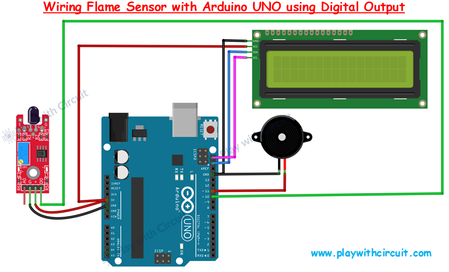
The wiring will be the same as we did during calibration. The only difference is that here we are not using the Analog output pin of flame sensor and we have added a buzzer whose red wire connected at pin 11 of the Arduino. The black wire of buzzer is connected to GND.
Arduino Code
This code shows how to interface flame sensor with Arduino UNO using Digital input pin of Arduino and display fire detected on I2C LCD.
/*
Interfacing Flame Sensor with Arduino UNO using Digital input pin of Arduino and displaying fire detected on I2C LCD. A buzzer is used which turns ON and OFF when there is fire.
There is one averaging filter which checks for false alarm by averaging the input counts
Code by www.playwithcircuit.com
*/

#include <LiquidCrystal_I2C.h>  // Library to Run I2C LCD

// Buzzer pin
#define BUZZER_PIN 11
// define the size of filter array
#define FILTER_SIZE 30

// Set the LCD address to 0x27 for a 16 chars and 2 line display
LiquidCrystal_I2C lcd(0x27, 16, 2);

// Define the digital input pin, for the flame sensor's digital output
const int FlameSensorDigitalPin = 10;

void setup() {
  // initialize the LCD
  lcd.init();
  // Turn ON the Backlight
  lcd.backlight();
  // Clear the display buffer
  lcd.clear();

  // Make digital pin of sensor as input
  pinMode(FlameSensorDigitalPin, INPUT);

  // Make buzzer pin as output
  pinMode(BUZZER_PIN, OUTPUT);

  // Turn OFF buzzer pin
  digitalWrite(BUZZER_PIN, LOW);

  // Print a message to the LCD
  lcd.setCursor(0, 0);
  lcd.print("Initializing");

  // Print a message to the LCD
  lcd.setCursor(0, 1);
  lcd.print("Please Wait...");

  // delay to make flame sensor stable
  delay(1000);

  // Clear the display buffer
  lcd.clear();

  // Print a message to the LCD
  lcd.setCursor(0, 0);
  lcd.print("Fire Detected:  ");

  // Print a message to the LCD
  lcd.setCursor(0, 1);
  lcd.print("                ");
}

void loop() {

  // when the Digital pin turns HIGH, it means flame is present
  if (checkFlameSensor() == HIGH) {
    lcd.setCursor(0, 1);
    lcd.print("YES");
    digitalWrite(BUZZER_PIN, !digitalRead(BUZZER_PIN));
    delay(100);
  } else {
    lcd.setCursor(0, 1);
    lcd.print("NO ");
    // Turn Off buzzer pin
    digitalWrite(BUZZER_PIN, LOW);
    // Wait for 10ms before the next loop
    delay(10);
  }
}

// this function checks flame sensor two times to check if flame is really detected or not
bool checkFlameSensor() {
  if (digitalRead(FlameSensorDigitalPin) == HIGH) {
    // wait for 20ms to check for signal debouncing
    delay(20);
    if (digitalRead(FlameSensorDigitalPin) == HIGH) {
      return HIGH;
    } else {
      return LOW;
    }
  } else {
    return LOW;
  }
}
Code Description
Inside the loop() function, the presence of a flame using the digital output of the flame sensor is continuously monitored. Instead of relying on the analog readings like in the previous code, this uses a custom function called checkFlameSensor() to verify whether a flame is detected more reliably.
First, the function checkFlameSensor() is called, and if it returns HIGH, it indicates that the flame sensor has detected a flame. The program then proceeds to alert the user by displaying “YES” on the second row of the LCD and toggles the state of the buzzer. This makes the buzzer beep repeatedly every 100 milliseconds, creating a noticeable alert signal when fire is detected.
If the flame is not detected, the program displays “NO “ on the LCD and ensures the buzzer is turned OFF. A short delay of 10 milliseconds is included at the end to slow down the loop slightly and reduce flicker on the LCD.
The checkFlameSensor() function reads the digital signal from the flame sensor once and checks if it’s HIGH, which would indicate flame presence. However, to ensure this isn’t due to noise or false triggering, it waits 20 milliseconds and checks again. Only if both readings are HIGH does it confirm that a flame is present and return HIGH. Otherwise, it returns LOW.