
Stepper motors are widely used in various applications that require precise control over motion. Unlike DC motors, which typically rotate continuously, stepper motors move in discrete steps. This makes them ideal for applications where precise positioning and controlled motion is required, such as 3D printers, CNC machines, robotic arms, and many other automated systems.
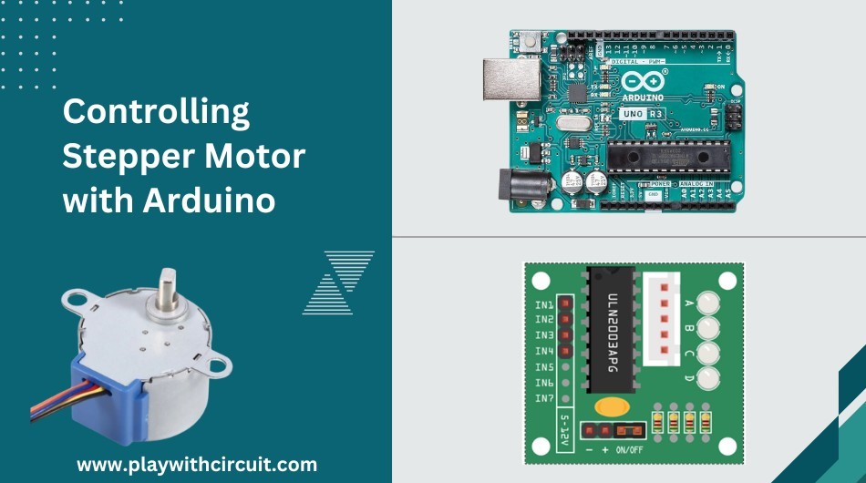
The 28-BYJ48 stepper motor is a popular choice among hobbyists and beginners due to its affordability and ease of use. In this tutorial you will learn how a stepper motor works, types of stepper motors, and how to control a stepper motor using a ULN2003 driver and an Arduino UNO board using different modes of operation.
How Does a Stepper Motor Work?
A stepper motor is a brushless, synchronous electric motor having a unique design to achieve precise control over rotation. It operates on the principle of electromagnetism. A stepper motor consists of a rotor (rotating part of the motor) and a stator(stationary part). In the stator, there are multiple sets of coils, arranged in such a way that they create magnetic poles when energized.
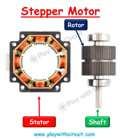
To understand the workings of a stepper motor, first understand that stepper motor takes small steps that combine to create a rotatory motion. Let us consider a stepper motor with four windings/coils. When an electrical current flows through one coil, it generates a magnetic field that either attracts or repels the permanent magnets in the rotor, causing it to align with the magnetic field of the stator. This alignment produces a step or a discrete movement. By sequentially energizing the coils in the correct sequence, the rotor can be made to rotate in a controlled manner.
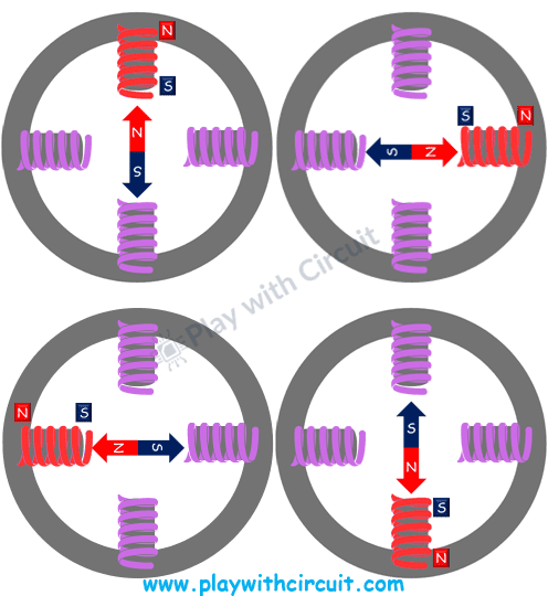
In the above image, we can see four coils arranged at the top, right, down, and left of the permanent magnet rotor present in the center. When the top coil is energized, it momentarily creates north and south poles, due to which the north pole of the permanent magnet rotor aligns with the top coil. Similarly, when the right coil is energized then the rotor aligns itself with the changing magnetic field. After that when the down coil and subsequently the left coil are energized then, the rotor aligns itself with the changing magnetic field, and after that when the top coil is energized the rotor completes one rotation in the clockwise direction.
Similarly, if the motor needs to be rotated in an anti-clockwise direction, then the sequence can be reversed top, left, down, right, and again top.
Thus, the sequence in which stepper motor’s coils are energised controls its direction of rotation. This sequence is managed by microcontrollers. Stepper motors are often controlled using the pulse signal from these controllers, with each pulse corresponding to one step. By varying the pulse frequency and sequence, precise control over the motor’s movement can be achieved.
Modes of operation in Stepper Motor
Stepper motor has three main operating modes:
Full Step Mode (Single Phase ON) or Wave Stepping
When one coil of each phase is energized sequentially, the stepper motor takes one full step. In this mode only one coil of the stepper motor is energized at a time. In step 1 only phase 1 is energized, in step 2 phase 2 is energized, in step 3 phase 3 is energized and in step 4 phase 4 is energized. Each phase is activated individually in a cyclic manner, creating a wave-like motion. This sequence causes the motor to complete a full step. While this mode consumes less power and generates less heat, it provides lower torque compared to other modes.
The order in which coils need to be energised is given in the following table:
| Step Sequence | Phase 1 | Phase 2 | Phase 3 | Phase 4 |
|---|---|---|---|---|
| 1 | 1 | 0 | 0 | 0 |
| 2 | 0 | 1 | 0 | 0 |
| 3 | 0 | 0 | 1 | 0 |
| 4 | 0 | 0 | 0 | 1 |
Full Step Mode (Two Phase ON)
In this mode, two phases are energized simultaneously. In step 1 phase 1 and 2 are energized at the same time, then in other steps next two phases are energized. This stepping sequence causes the motor to complete one full step.
In this mode the motor operates at its maximum torque. However, it can result in higher noise and vibrations. This mode is best suited for applications needing high torque over precision.
The pattern of energising the coils is given in the following table:
| Step Sequence | Phase 1 | Phase 2 | Phase 3 | Phase 4 |
|---|---|---|---|---|
| 1 | 1 | 1 | 0 | 0 |
| 2 | 0 | 1 | 1 | 0 |
| 3 | 0 | 0 | 1 | 1 |
| 4 | 1 | 0 | 0 | 1 |
Half Step Mode
Half-step mode is a combination of the previous two modes. This results in steps that are half the size of full steps, effectively doubling the number of steps per rotation. In this mode the coils are energized in such a way that first one coil is activated at a time and then two coils are activated simultaneously but at a low current level. It results in smaller steps as compared to full steps.
The smaller steps results in smoother operation, better resolution, and reduced noise and vibrations, enhancing the motor’s precision and control.
The pattern of energising the coils is given in the following table:
| Step Sequence | Phase 1 | Phase 2 | Phase 3 | Phase 4 |
|---|---|---|---|---|
| 1 | 1 | 0 | 0 | 0 |
| 2 | 1 | 1 | 0 | 0 |
| 3 | 0 | 1 | 0 | 0 |
| 4 | 0 | 1 | 1 | 0 |
| 5 | 0 | 0 | 1 | 0 |
| 6 | 0 | 0 | 1 | 1 |
| 7 | 0 | 0 | 0 | 1 |
| 8 | 1 | 0 | 0 | 1 |
Microstepping Mode
Microstepping is an advanced mode for achieving precise motor control by dividing each step into smaller micro steps. Instead of fully energising coils, it varies the current levels, allowing the rotor to hold positions accurately. This results in high precision, low vibration, and quiet operation. Microstepping offers better control compared to full-step and half-step modes.
Types of Stepper Motors
Stepper motors can be classified into two types based on construction:
- Permanent Magnet Stepper Motor: Permanent magnet stepper motor has a rotor made of strong permanent magnets and the stator is constructed of a series of electromagnetic coils. The coils are arranged in a circular pattern around the rotor. When a current is applied to one of the coils, it generates a magnetic field, which attracts the permanent magnets in the rotor toward it causing the rotor to move in a precise and controlled manner. These motors are efficient, requiring low power to generate high torque, making them a good choice for applications where energy efficiency and strong performance are needed.
- Variable Reluctance Stepper Motor: Variable reluctance stepper motor has a rotor made of plain iron and has teeth around its circumference, similar to a gear. These teeth allow for very precise movements, making these motors highly accurate. However, this precision often means they have less torque compared to other types. Variable reluctance steppers are perfect for applications where accuracy is more important than strength.
- Hybrid Synchronous Stepper Motor: This motor combines the features of both the permanent magnet and variable reluctance stepper motors. It has a permanent magnet core and a toothed circumference made of iron. This combination enables them to move in very small, precise steps and high torque. They are powerful and precise, making them ideal for applications where both accuracy and strength are important.
Stepper motors can be classified into two types based on Stator Windings:
- Bipolar Stepper Motor: Bipolar stepper motor has a single winding per stator phase and no center tap. It has four wires, corresponding to the two ends of each winding. This configuration allows the entire winding to be utilized, resulting in higher torque output and better efficiency. Driving a bipolar motor typically involves using an H-bridge circuit to control the current flow.
- Unipolar Stepper Motor: Unipolar stepper motors have center-tapped windings for each phase. Each phase effectively has two windings, with the center tap providing a common connection. This configuration often uses a single transistor or switch to energize each half of the winding.
In this motor, only half of the winding is used at any time, resulting in lower torque output and efficiency compared to bipolar motors.
Introduction to 28BYJ-48 Stepper Motor
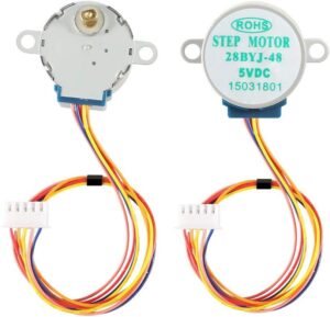
The 28BYJ-48 is a widely used unipolar 5V stepper motor among hobbyists and DIY enthusiasts due to its low cost, compact size, and ease of use. It comes with a reduction gearbox attached to the shaft, providing higher torque output.
One notable feature of the 28BYJ-48 stepper motor is its 5-wire interface, which includes four coils (wires) for controlling the motor and one common wire. By energizing the coils in the correct sequence, you can make the motor step forward or backward with precision.
28BYJ-48 Stepper Motor Specifications
Some key specifications of the 28BYJ-48 stepper motor include:
| Rated voltage | 5V |
| Coil Type | Unipolar |
| Coil Resistance | 50 Ohms ±7% (25°C) |
| Gear Reduction | 1/64 |
| Stride Angle | 5.625 ° |
| Steps per Revolution | Half-step mode: 4096 Full step mode: 2048 |
| Motor Type | Permanent Magnet Gear Motor |
| Number of Phases | 4 |
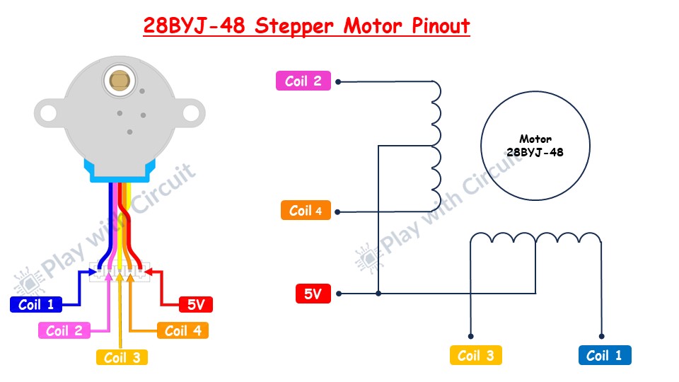
28BYJ-48 Stepper Motor Pinout
The 28BYJ-48 stepper motor has five wires and four coils that are internally connected to form two center-tapped coils. One end of all the coils are connect to +5V (red wire) and the other end of each coil is pulled out as wires colored Orange, Pink, Yellow and Blue.
For more information, please refer to the datasheet below.
What is the Gear Reduction Ratio?
The gear ratio of the 28BYJ-48 stepper motor is usually 64:1, meaning that for every 64 rotations of the motor’s central shaft, the output shaft completes one full rotation. A higher gear ratio increases torque but decreases speed, while a lower gear ratio increases speed but reduces torque.
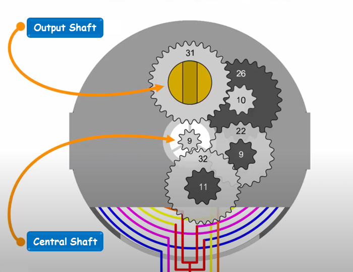
Let us understand in detail how we came to the number 64. Let’s break it into multiple steps:
Step 1: In step 1 the permanent magnet rotor present in the center is connected to the gear which has 9 spokes, these 9 spokes drive the gear which has 32 spokes. The gear having 9 spokes needs to be rotated multiple times to rotate the gear having 32 spokes for one single rotation.
The gear reduction ratio in this step is 32/9 = 3.56.
Step 2: In this step, the gear which has 32 spokes attached parallel to the gear having 11 spokes which drives the gear having 22 spokes.
The gear reduction ratio in this step is 22/11 = 2.0.
Step 3: In this step, the gear which has 22 spokes attached parallel to the gear having 9 spokes which drives the gear having 26 spokes.
The gear reduction ratio in this step is 26/9 = 2.89.
Step 4: In this step, the gear which has 26 spokes attached parallel to the gear having 10 spokes which drives the gear having 31 spokes.
The gear reduction ratio in this step is 31/10 = 3.1.
The output shaft is connected to the final gear having 31 spokes.
Hence the final gear reduction ratio is 3.56*2.0*2.89*3.1 = 63.78 which is approximately equivalent to 64.
It means the central shaft needs to be rotated 64 times for one complete rotation of the output shaft in the 28BYJ-48 stepper motor.
What is Stride Angle?
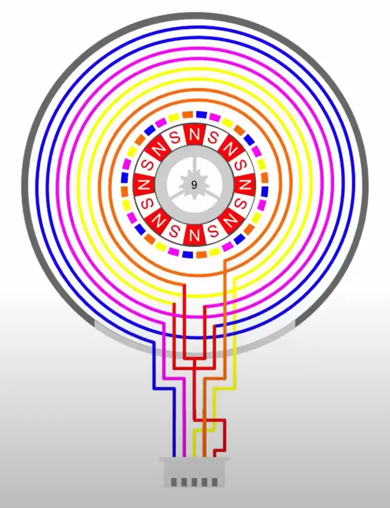
The stride angle is the minimum rotatory step a stepper motor can take. It is 5.625 degrees for the 28BYJ-48 stepper motor.
The rotor of the motor is a permanent magnet having 8 pairs of North-South Pole.
The internal construction of the 28BYJ-48 stepper motor is such that it creates a total of 32 poles. As shown in the above diagram blue coil creates 8 poles shown as 8 rectangles of blue colour, similarly, all other coils pink, yellow, and orange coil create 8 poles each. Hence a total of 32 poles are created. Therefore, the total number of steps to complete one rotation of 360 degrees is 32.
When one coil is energized the 8 pairs of poles of rotor align themselves with the 8 magnetic poles of that coil. Similarly, when another coil is energized, the rotor aligns itself with the newly created magnetic field.
The motor rotates in one direction as long as the right coils are energized back to back to create a full rotation from small-small steps.
Hence in one step, the motor rotates = 360/32 =11.25 degrees.
Therefore, in half step, it rotates = 11.25/2 = 5.625.
This is how the Stride Angle is calculated for a 28BYJ-48 stepper motor.
Calculation of the number of steps for one complete rotation
From the above discussion, it is clear that the 28BYJ-48 stepper motor central shaft requires 32 steps to complete one rotation.
The gear reduction ratio of this motor is 64 hence it requires a total of 32 x 64 = 2048 steps of the central shaft to complete one full rotation of the output shaft.
In another way, we can say that it takes 32 x 64 x 2 = 4096 half steps to complete one full rotation of the output shaft.
Calculation of delay between two steps
Let’s take an example we need to run the stepper motor at a speed of 15 rotations per minute.
In 1 minute, the motor rotates 15 rotations.
15 rotations = 15* 2048 steps.
In 1 minute i.e., 60 seconds the motor should take 15* 2048 steps.
This is equivalent to taking 15 * 2048 steps in 60,000 milliseconds.
Hence number of steps in 1ms = (15 * 2048)/60000 = 0.512 steps i.e., approximately 1 step in 2ms.
Hence to run the motor at an speed of 15 rpm, it requires a delay of 2ms after every step. In another words, we can say that it would require a delay of 1ms after every half step.
ULN2003 Stepper Motor Driver Module
To control the 28BYJ-48 stepper motor, a driver circuit is required that can handle the heavy current demands of stepper motors typically around 240mA. The Arduino pins cannot provide such a large amount of current. Therefore, this motor comes with a ULN2003 driver board. The ULN2003 driver board serves as an interface between the Arduino and the stepper motor, providing the necessary current amplification and protection.
The ULN2003 driver IC contains seven high-voltage, high-current Darlington transistor pairs, allowing it to drive the four coil windings of the stepper motor. Each pair can drive 500mA and 50V load. In this board, 4 out of 7 pairs are used.
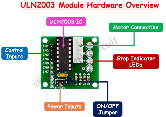
ULN2003 Module Pinout
The ULN2003 stepper driver board pinout is given as follows:
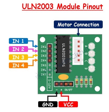
IN1-IN4 These are motor control input pins. They are connected to the digital output pins of the Arduino to control the direction and step sequence of the stepper motor.
GND This is the ground pin.
VCC This pin powers the motor. Due to the high-power consumption of the motor, it’s recommended to use an external 5V power supply rather than drawing power from the Arduino.
Motor Connection This is where the stepper motor plugs into the driver module.
❕Note
In ULN2003 module the ON/OFF jumper must be connected to provide power to the IC.
Interfacing 28BYJ-48 stepper motor with Arduino Uno
Now that we have a basic understanding of the components involved, let’s proceed with setting up the hardware for controlling the 28BYJ-48 stepper motor using an Arduino and ULN2003 driver.
Hardware and Software Requirements
Hardware
| Component Name | Quantity | Remarks | Where to Buy |
|---|---|---|---|
| 28BYJ-48 stepper motor | 1 | Unipolar stepper motor | Amazon |
| Arduino UNO R3 | 1 | Revision R3 | Amazon |
| ULN2003 driver module | 1 | For driving stepper motor | Amazon |
| Jumper wires | 10 | For Motor, driver and Arduino connections | Amazon |
| USB cable type A/B | 1 | for programming Arduino UNO | Amazon |
| 5V power supply | 1 | For providing external power supply to driver module | Amazon |
Software
- Arduino IDE, Version 2.1.1 or above installed on your PC
- Stepper Library by Arduino version 1.1.3
Commonly Used Functions of Stepper Library
stepper()
This function creates a new instance of the Stepper class that represents the stepper motor connected to the Arduino board.
Syntax
Stepper(steps, pin1, pin2)
Stepper(steps, pin1, pin2, pin3, pin4)
Parameters
- steps: The number of steps in one revolution of your motor.
- pin1, pin2, pin3, pin4: The pins connected to the motor.
Returns: A new instance of the Stepper motor class.
setSpeed()
This function sets the motor speed in rotations per minute (RPMs).
Syntax
setSpeed(rpms)Parameters
- rpms: the speed at which the motor should turn in rotations per minute (positive long).
Returns: None
step()
This function turns the motor a specific number of steps, at a speed determined by the most recent call to setSpeed(). This function is blocking, meaning it will wait until the motor has completed the specified number of steps before moving on to the next line of code in your sketch. For instance, if you set a low speed (e.g., 1 RPM) and call step(100) on a motor with 100 steps per revolution, the function would take a full minute to execute.
Syntax
step(steps)Parameters
- steps: the number of steps to turn the motor. Positive integer to turn one direction, negative integer to turn the other.
Returns: None
Pin Connections between ULN2003 Driver and Arduino Uno
| ULN2003 Driver | Arduino |
|---|---|
| IN1 | 7 |
| IN2 | 6 |
| IN3 | 5 |
| IN4 | 4 |
| GND | GND |
Wiring Diagram
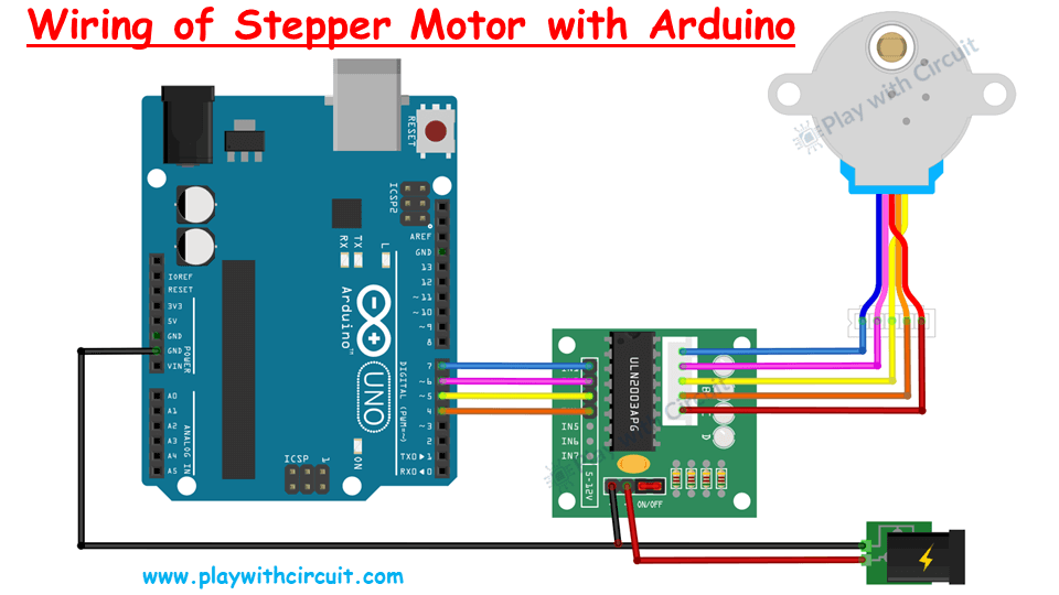
The connections are pretty simple. First, connect an external 5V power supply to the ULN2003 driver. Then, connect the driver’s IN1, IN2, IN3, and IN4 to Arduino digital pins 7, 6, 5, and 4, respectively.
Next, connect the stepper motor to the ULN2003 driver. Finally, ensure the circuit and Arduino share a common ground.
Warning
Powering the stepper motor directly from Arduino is not recommended as it may damage Arduino. Always use external power supply to power a stepper motor because it reduces electrical noise, preventing instability and damage. It also manages voltage spikes, protecting the Arduino from harmful fluctuations.
Arduino Example Code 1
In the below code, we will be rotating the stepper motor in the clockwise and anti-clockwise direction. One complete rotation in both directions. We will be using the Stepper library by Arduino.
/*
Interfacing Stepper Motor with Arduino UNO using Stepper Library using ULN 2003 Motor driver board by www.playwithcircuit.com
*/

#include <Stepper.h>

//define Input pins of the Motor
#define OUTPUT1   7                // Connected to the Blue coloured wire
#define OUTPUT2   6                // Connected to the Pink coloured wire
#define OUTPUT3   5                // Connected to the Yellow coloured wire
#define OUTPUT4   4                // Connected to the Orange coloured wire

// Define the number of steps per rotation
const int stepsPerRotation = 2048;  // 28BYJ-48 has 2048 steps per rotation in full step mode as given in data sheet

// Initialize the stepper motor with the sequence of control pins OUTPUT1, OUTPUT3, OUTPUT2, IN4
// OUTPUT1 and OUTPUT3 are connected to one coil and OUTPUT2 and OUTPUT4 are connected to one Coil
Stepper myStepper(stepsPerRotation, OUTPUT1, OUTPUT3, OUTPUT2, OUTPUT4);
void setup() {
  // Set the speed of the motor in RPM (adjust as needed)
  myStepper.setSpeed(15);  // 15 RPM
}

void loop() {
  // Rotate in One Direction and complete one complete rotation i.e 2048 steps
  myStepper.step(stepsPerRotation);
  delay(1000);  // Delay between rotations
  // For Rotation in opposite direction provide the variable to the parameter with negative Sign
  myStepper.step(-stepsPerRotation);
  delay(1000);  // Delay between rotations
}
Code Explanation
The code starts by including the Stepper library, which provides functions to control stepper motors.
#include <Stepper.h>The pins connected to the stepper motor are defined using #define statements. These pins correspond to the wires of the 28BYJ-48 stepper motor.
#define OUTPUT1   7  // Connected to the Blue coloured wire
#define OUTPUT2   6  // Connected to the Pink coloured wire
#define OUTPUT3   5  // Connected to the Yellow coloured wire
#define OUTPUT4   4  // Connected to the Orange coloured wire
The number of steps per full rotation for the motor is defined. For the 28BYJ-48 motor, this is typically 2048 steps in full step mode.
const int stepsPerRotation = 2048; // 28BYJ-48 has 2048 steps per rotation in full step modeA stepper object is created with the number of steps per rotation and the motor pins. The sequence of control pins is important for the correct operation of the motor.
Stepper myStepper(stepsPerRotation, OUTPUT1, OUTPUT3, OUTPUT2, OUTPUT4);In the setup() function, the speed of the stepper motor is set using the setSpeed() function. The speed is set in RPM (rotations per minute).
void setup() {
  myStepper.setSpeed(15);  // 15 RPM
}
The loop() function contains the main logic to control the motor. The motor is instructed to complete one full rotation in one direction using the step() function and then another full rotation in the opposite direction.
myStepper.step(stepsPerRotation); rotates the motor 2048 steps forward.A delay of 1000 milliseconds (1 second) is added between rotations to observe the motor’s movement.
myStepper.step(-stepsPerRotation); rotates the motor 2048 steps backward.Another delay of 1000 milliseconds is added.
void loop() {
  myStepper.step(stepsPerRotation);  // Rotate forward
  delay(1000);  // Delay between rotations
  myStepper.step(-stepsPerRotation);  // Rotate backward
  delay(1000);  // Delay between rotations
}
Arduino Example Code 2
In the below code, we will be rotating the stepper motor in the clockwise and anti-clockwise direction. One complete rotation in both directions. In this code, we will not use any Library, and operation mode will be full step mode (Single Phase ON).
/*
Interfacing Stepper Motor with Arduino UNO without using any Library in full step mode (Single Phase ON) using ULN 2003 Motor driver board by www.playwithcircuit.com
*/

#define OUTPUT1   7                // Connected to the Blue coloured wire
#define OUTPUT2   6                // Connected to the Pink coloured wire
#define OUTPUT3   5                // Connected to the Yellow coloured wire
#define OUTPUT4   4                // Connected to the Orange coloured wire

#define DELAY 2                   // delay after every step

void setup() {
  pinMode(OUTPUT1, OUTPUT);
  pinMode(OUTPUT2, OUTPUT);
  pinMode(OUTPUT3, OUTPUT);
  pinMode(OUTPUT4, OUTPUT);
}

void loop() {
  /* Rotation in one direction, one full rotation in full-step operation Mode*/
  for(int i = 0; i<512; i++)
  {
    digitalWrite(OUTPUT1, HIGH);
    digitalWrite(OUTPUT2, LOW);
    digitalWrite(OUTPUT3, LOW);
    digitalWrite(OUTPUT4, LOW);
    delay(DELAY);
    digitalWrite(OUTPUT1, LOW);
    digitalWrite(OUTPUT2, HIGH);
    digitalWrite(OUTPUT3, LOW);
    digitalWrite(OUTPUT4, LOW);
    delay(DELAY);
    digitalWrite(OUTPUT1, LOW);
    digitalWrite(OUTPUT2, LOW);
    digitalWrite(OUTPUT3, HIGH);
    digitalWrite(OUTPUT4, LOW);
    delay(DELAY);
    digitalWrite(OUTPUT1, LOW);
    digitalWrite(OUTPUT2, LOW);
    digitalWrite(OUTPUT3, LOW);
    digitalWrite(OUTPUT4, HIGH);
    delay(DELAY);
  }
  digitalWrite(OUTPUT1, LOW);
  digitalWrite(OUTPUT2, LOW);
  digitalWrite(OUTPUT3, LOW);
  digitalWrite(OUTPUT4, LOW);
  delay(1000);
  /* Rotation in opposite direction, one full rotation in full-step operation Mode*/
  for(int j = 0; j<512; j++)
  {
    digitalWrite(OUTPUT1, LOW);
    digitalWrite(OUTPUT2, LOW);
    digitalWrite(OUTPUT3, LOW);
    digitalWrite(OUTPUT4, HIGH);
    delay(DELAY);
    digitalWrite(OUTPUT1, LOW);
    digitalWrite(OUTPUT2, LOW);
    digitalWrite(OUTPUT3, HIGH);
    digitalWrite(OUTPUT4, LOW);
    delay(DELAY);
    digitalWrite(OUTPUT1, LOW);
    digitalWrite(OUTPUT2, HIGH);
    digitalWrite(OUTPUT3, LOW);
    digitalWrite(OUTPUT4, LOW);
    delay(DELAY);
    digitalWrite(OUTPUT1, HIGH);
    digitalWrite(OUTPUT2, LOW);
    digitalWrite(OUTPUT3, LOW);
    digitalWrite(OUTPUT4, LOW);
    delay(DELAY);
  }
  digitalWrite(OUTPUT1, LOW);
  digitalWrite(OUTPUT2, LOW);
  digitalWrite(OUTPUT3, LOW);
  digitalWrite(OUTPUT4, LOW);
  delay(1000);
}
Code Explanation
The pins connected to the stepper motor are defined using #define statements. These pins correspond to the wires of the 28BYJ-48 stepper motor.
A delay constant is defined to control the speed of the motor’s steps.
#define OUTPUT1   7  // Connected to the Blue coloured wire
#define OUTPUT2   6  // Connected to the Pink coloured wire
#define OUTPUT3   5  // Connected to the Yellow coloured wire
#define OUTPUT4   4  // Connected to the Orange coloured wire

define DELAY 2  // delay after every step
The setup() function sets the motor pins as outputs using the pinMode() function. This prepares the pins to send signals to the motor.
void setup() {
  pinMode(OUTPUT1, OUTPUT);
  pinMode(OUTPUT2, OUTPUT);
  pinMode(OUTPUT3, OUTPUT);
  pinMode(OUTPUT4, OUTPUT);
}
The loop() function consists of two main parts: rotating the motor in one direction and then in the opposite direction. Each step sequence sets the appropriate pins HIGH or LOW to energize the coils in the correct order, causing the motor to take step.
The first for loop rotates the motor in one direction for a full rotation. The sequence of digitalWrite() sets one coil HIGH and the others LOW in a specific order to make the motor rotate. Here motor is being driven in Full Step Mode (Single Phase ON) or Wave Stepping Mode .
void loop() {
  for(int i = 0; i<512; i++) {
    digitalWrite(OUTPUT1, HIGH);
    digitalWrite(OUTPUT2, LOW);
    digitalWrite(OUTPUT3, LOW);
    digitalWrite(OUTPUT4, LOW);
    delay(DELAY);
    digitalWrite(OUTPUT1, LOW);
    digitalWrite(OUTPUT2, HIGH);
    digitalWrite(OUTPUT3, LOW);
    digitalWrite(OUTPUT4, LOW);
    delay(DELAY);
    digitalWrite(OUTPUT1, LOW);
    digitalWrite(OUTPUT2, LOW);
    digitalWrite(OUTPUT3, HIGH);
    digitalWrite(OUTPUT4, LOW);
    delay(DELAY);
    digitalWrite(OUTPUT1, LOW);
    digitalWrite(OUTPUT2, LOW);
    digitalWrite(OUTPUT3, LOW);
    digitalWrite(OUTPUT4, HIGH);
    delay(DELAY);
  }
  digitalWrite(OUTPUT1, LOW);
  digitalWrite(OUTPUT2, LOW);
  digitalWrite(OUTPUT3, LOW);
  digitalWrite(OUTPUT4, LOW);
  delay(1000);
The second for loop rotates the motor in the opposite direction for a full rotation. The sequence of digitalWrite() is reversed compared to the first loop.
Again, a delay is added between steps to control the speed.
for(int j = 0; j<512; j++) {
    digitalWrite(OUTPUT1, LOW);
    digitalWrite(OUTPUT2, LOW);
    digitalWrite(OUTPUT3, LOW);
    digitalWrite(OUTPUT4, HIGH);
    delay(DELAY);
    digitalWrite(OUTPUT1, LOW);
    digitalWrite(OUTPUT2, LOW);
    digitalWrite(OUTPUT3, HIGH);
    digitalWrite(OUTPUT4, LOW);
    delay(DELAY);
    digitalWrite(OUTPUT1, LOW);
    digitalWrite(OUTPUT2, HIGH);
    digitalWrite(OUTPUT3, LOW);
    digitalWrite(OUTPUT4, LOW);
    delay(DELAY);
    digitalWrite(OUTPUT1, HIGH);
    digitalWrite(OUTPUT2, LOW);
    digitalWrite(OUTPUT3, LOW);
    digitalWrite(OUTPUT4, LOW);
    delay(DELAY);
  }
  digitalWrite(OUTPUT1, LOW);
  digitalWrite(OUTPUT2, LOW);
  digitalWrite(OUTPUT3, LOW);
  digitalWrite(OUTPUT4, LOW);
  delay(1000);
}
Arduino Example Code 3
In the below code, we will be rotating the stepper motor in the clockwise and anti-clockwise direction. One complete rotation in both directions. In this code, we will not use any Library, and operation mode will be full-step mode having Two Phase ON at a time.
/*
Interfacing Stepper Motor with Arduino UNO without using any Library In full step Operation Mode, having two phase ON at a time using ULN 2003 Motor driver board by www.playwithcircuit.com
*/

#define OUTPUT1   7                // Connected to the Blue coloured wire
#define OUTPUT2   6                // Connected to the Pink coloured wire
#define OUTPUT3   5                // Connected to the Yellow coloured wire
#define OUTPUT4   4                // Connected to the Orange coloured wire

#define DELAY 2                   // delay after every step

void setup() {
  pinMode(OUTPUT1, OUTPUT);
  pinMode(OUTPUT2, OUTPUT);
  pinMode(OUTPUT3, OUTPUT);
  pinMode(OUTPUT4, OUTPUT);
}

void loop() {
  /* Rotation in one direction, one full rotation in full-step operation Mode*/
  for(int i = 0; i<512; i++)
  {
    digitalWrite(OUTPUT1, HIGH);
    digitalWrite(OUTPUT2, HIGH);
    digitalWrite(OUTPUT3, LOW);
    digitalWrite(OUTPUT4, LOW);
    delay(DELAY);
    digitalWrite(OUTPUT1, LOW);
    digitalWrite(OUTPUT2, HIGH);
    digitalWrite(OUTPUT3, HIGH);
    digitalWrite(OUTPUT4, LOW);
    delay(DELAY);
    digitalWrite(OUTPUT1, LOW);
    digitalWrite(OUTPUT2, LOW);
    digitalWrite(OUTPUT3, HIGH);
    digitalWrite(OUTPUT4, HIGH);
    delay(DELAY);
    digitalWrite(OUTPUT1, HIGH);
    digitalWrite(OUTPUT2, LOW);
    digitalWrite(OUTPUT3, LOW);
    digitalWrite(OUTPUT4, HIGH);
    delay(DELAY);
  }
  digitalWrite(OUTPUT1, LOW);
  digitalWrite(OUTPUT2, LOW);
  digitalWrite(OUTPUT3, LOW);
  digitalWrite(OUTPUT4, LOW);
  delay(1000);
  /* Rotation in opposite direction, one full rotation in full-step operation Mode*/
  for(int j = 0; j<512; j++)
  {
    digitalWrite(OUTPUT1, HIGH);
    digitalWrite(OUTPUT2, LOW);
    digitalWrite(OUTPUT3, LOW);
    digitalWrite(OUTPUT4, HIGH);
    delay(DELAY);
    digitalWrite(OUTPUT1, LOW);
    digitalWrite(OUTPUT2, LOW);
    digitalWrite(OUTPUT3, HIGH);
    digitalWrite(OUTPUT4, HIGH);
    delay(DELAY);
    digitalWrite(OUTPUT1, LOW);
    digitalWrite(OUTPUT2, HIGH);
    digitalWrite(OUTPUT3, HIGH);
    digitalWrite(OUTPUT4, LOW);
    delay(DELAY);
    digitalWrite(OUTPUT1, HIGH);
    digitalWrite(OUTPUT2, HIGH);
    digitalWrite(OUTPUT3, LOW);
    digitalWrite(OUTPUT4, LOW);
    delay(DELAY);
  }
  digitalWrite(OUTPUT1, LOW);
  digitalWrite(OUTPUT2, LOW);
  digitalWrite(OUTPUT3, LOW);
  digitalWrite(OUTPUT4, LOW);
  delay(1000);
}
Code Explanation
In this code, initialization and pin setup is the same as previous code. The main difference lies in the loop function, particularly in the sequence of digitalWrite to control the stepper motor. Here each step turns on two coils at a time in both directions, then waiting for the defined delay. Here stepper motor is being driven in Full Step Mode (Two Phase ON).
Arduino Example Code 4
In the below code, we will be rotating the stepper motor in the clockwise and anti-clockwise direction. One complete rotation in both directions. In this code, we will not use any Library, and the operation mode will be half-step mode.
/*
Interfacing Stepper Motor with Arduino UNO without using any Library in half step Operation Mode using ULN 2003 Motor driver board by www.playwithcircuit.com
*/

#define OUTPUT1   7                // Connected to the Blue coloured wire
#define OUTPUT2   6                // Connected to the Pink coloured wire
#define OUTPUT3   5                // Connected to the Yellow coloured wire
#define OUTPUT4   4                // Connected to the Orange coloured wire

#define DELAY 1                   // delay after every half step

void setup() {
  pinMode(OUTPUT1, OUTPUT);
  pinMode(OUTPUT2, OUTPUT);
  pinMode(OUTPUT3, OUTPUT);
  pinMode(OUTPUT4, OUTPUT);
}

void loop() {
  /* Rotation in one direction, one full rotation in half-step operation Mode*/
  for(int i = 0; i<512; i++)
  {
    digitalWrite(OUTPUT1, HIGH);
    digitalWrite(OUTPUT2, LOW);
    digitalWrite(OUTPUT3, LOW);
    digitalWrite(OUTPUT4, LOW);
    delay(DELAY);
    digitalWrite(OUTPUT1, HIGH);
    digitalWrite(OUTPUT2, HIGH);
    digitalWrite(OUTPUT3, LOW);
    digitalWrite(OUTPUT4, LOW);
    delay(DELAY);
    digitalWrite(OUTPUT1, LOW);
    digitalWrite(OUTPUT2, HIGH);
    digitalWrite(OUTPUT3, LOW);
    digitalWrite(OUTPUT4, LOW);
    delay(DELAY);
    digitalWrite(OUTPUT1, LOW);
    digitalWrite(OUTPUT2, HIGH);
    digitalWrite(OUTPUT3, HIGH);
    digitalWrite(OUTPUT4, LOW);
    delay(DELAY);
    digitalWrite(OUTPUT1, LOW);
    digitalWrite(OUTPUT2, LOW);
    digitalWrite(OUTPUT3, HIGH);
    digitalWrite(OUTPUT4, LOW);
    delay(DELAY);
    digitalWrite(OUTPUT1, LOW);
    digitalWrite(OUTPUT2, LOW);
    digitalWrite(OUTPUT3, HIGH);
    digitalWrite(OUTPUT4, HIGH);
    delay(DELAY);
    digitalWrite(OUTPUT1, LOW);
    digitalWrite(OUTPUT2, LOW);
    digitalWrite(OUTPUT3, LOW);
    digitalWrite(OUTPUT4, HIGH);
    delay(DELAY);
    digitalWrite(OUTPUT1, HIGH);
    digitalWrite(OUTPUT2, LOW);
    digitalWrite(OUTPUT3, LOW);
    digitalWrite(OUTPUT4, HIGH);
    delay(DELAY);
  }
  digitalWrite(OUTPUT1, LOW);
  digitalWrite(OUTPUT2, LOW);
  digitalWrite(OUTPUT3, LOW);
  digitalWrite(OUTPUT4, LOW);
  delay(1000);
  /* Rotation in opposite direction, one full rotation in half-step operation Mode*/
  for(int j = 0; j<512; j++)
  {
    digitalWrite(OUTPUT1, LOW);
    digitalWrite(OUTPUT2, LOW);
    digitalWrite(OUTPUT3, LOW);
    digitalWrite(OUTPUT4, HIGH);
    delay(DELAY);
    digitalWrite(OUTPUT1, LOW);
    digitalWrite(OUTPUT2, LOW);
    digitalWrite(OUTPUT3, HIGH);
    digitalWrite(OUTPUT4, HIGH);
    delay(DELAY);
    digitalWrite(OUTPUT1, LOW);
    digitalWrite(OUTPUT2, LOW);
    digitalWrite(OUTPUT3, HIGH);
    digitalWrite(OUTPUT4, LOW);
    delay(DELAY);
    digitalWrite(OUTPUT1, LOW);
    digitalWrite(OUTPUT2, HIGH);
    digitalWrite(OUTPUT3, HIGH);
    digitalWrite(OUTPUT4, LOW);
    delay(DELAY);
    digitalWrite(OUTPUT1, LOW);
    digitalWrite(OUTPUT2, HIGH);
    digitalWrite(OUTPUT3, LOW);
    digitalWrite(OUTPUT4, LOW);
    delay(DELAY);
    digitalWrite(OUTPUT1, HIGH);
    digitalWrite(OUTPUT2, HIGH);
    digitalWrite(OUTPUT3, LOW);
    digitalWrite(OUTPUT4, LOW);
    delay(DELAY);
    digitalWrite(OUTPUT1, HIGH);
    digitalWrite(OUTPUT2, LOW);
    digitalWrite(OUTPUT3, LOW);
    digitalWrite(OUTPUT4, LOW);
    delay(DELAY);
    digitalWrite(OUTPUT1, HIGH);
    digitalWrite(OUTPUT2, LOW);
    digitalWrite(OUTPUT3, LOW);
    digitalWrite(OUTPUT4, HIGH);
    delay(DELAY);
  }
  digitalWrite(OUTPUT1, LOW);
  digitalWrite(OUTPUT2, LOW);
  digitalWrite(OUTPUT3, LOW);
  digitalWrite(OUTPUT4, LOW);
  delay(1000);
}
Code Explanation
In this code also, initialization and pin setup is the same as previous codes. Here the motor is operated in half-step mode so the stepping sequence is different in loop() function. The motor steps through eight states. Here stepper motor is being driven in Half Step Mode.
Video
FAQ’S
Why is my stepper motor vibrating but not rotating?
This could be due to incorrect step sequence or insufficient current. Check your step sequence in the code to ensure it matches the motor’s requirements. Also, make sure the motor driver is providing enough current to the motor. Adjusting the speed setting in your code might also help.
How do I control the speed of my stepper motor using Arduino?
You can control the speed of the stepper motor by setting the speed parameter in the Arduino code. Using the setSpeed() function from the Arduino Stepper library allows you to define the speed in RPM (rotations per minute). Adjusting this value will change the motor’s speed
How do I determine the number of steps per revolution for my stepper motor?
The number of steps per revolution depends on the motor’s step angle. For example, if a motor has a step angle of 11.25 degrees, it would take 32 steps to complete one full revolution (360 degrees / 11.25 degrees per step). This value is typically specified in the motor’s datasheet
How can I troubleshoot a non-functional stepper motor setup?
To troubleshoot, start by checking all connections, ensuring the power supply is adequate, and verifying that the ground is common between Arduino and the driver. Then, check the stepper motor code for correct step sequences and speed settings. Using a multimeter, you can also check the output voltages at the driver module to ensure proper operation.


