I2C is a digital communication protocol that enables communication between devices over short distances. The protocol uses a two-wire communication interface that allows you to connect multiple controllers and multiple peripheral devices such as sensor arrays, displays, IoT devices, OLED displays, etc.
In this tutorial we will learn about the basics of I2C Communication and how data is transferred using this protocol.
What is the I2C Communication Protocol?
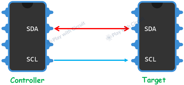
I2C or Inter-Integrated Circuit protocol is a serial communication protocol which uses just two wires for transmitting and receiving data. It is bidirectional, half-duplex communication where only a single controller or a target device can send/receive data at a time.
This protocol supports multiple controllers and multiple target devices on the same bus. This allows you to add or remove devices without disrupting the communication bus.
💡Must Read
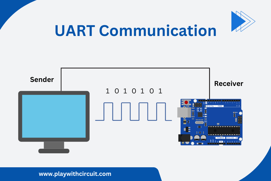
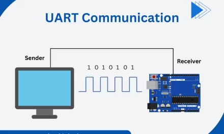
UART Communication Protocol
This article explains what is UART protocol and how it works.
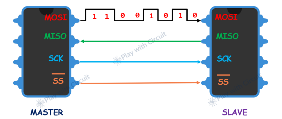
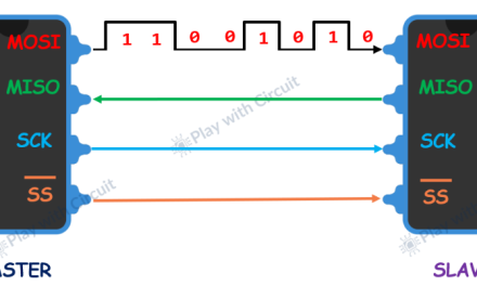
SPI Communication Protocol
This article will discuss the fundamentals of SPI, how it works and its configurations.
I2C Communication Hardware
The I2C Bus
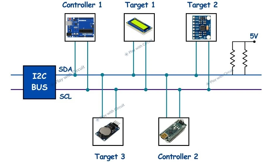
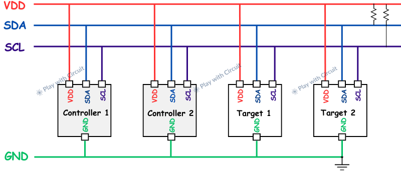
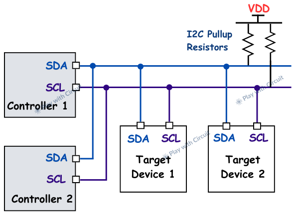
The I2C system uses two shared communication lines for each device on the bus. The two lines are:
- SCL (Serial Clock) – This line is used to transfer the data between controller and target device.
- SDA (Serial Data) – This line carries the clock signal generated by the controller.
The SDA and SCL lines have an open-drain connection hence external pull up resistors are required on both the lines. A device can pull the line LOW during active communication and allow it to return to HIGH state during idle period.
All the devices in I2C system are connected to the same SCL and SDA lines as shown below:
What is an Open Drain Connection?
Open-drain connections are used by both the data lines SDA and SCL, and connected to an NMOS transistor. This open drain connection controls the I2C communication line. The Open drain refers to the NMOS in which the drain is not connected to VDD and hence it needs to be pulled up externally. Below figures show the open-drain connection when the NMOS is turned ON.
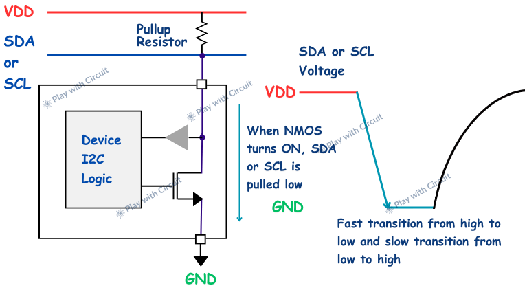
When the NMOS is turned ON the line connected to the drain is pulled LOW. The transition from HIGH to LOW is fast, as the NMOS actively pulls the line down and the speed of transition is determined by NMOS drive strength and bus capacitance of the line.
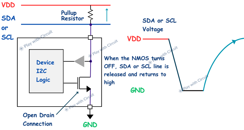
When the NMOS is turned OFF, the device stops pulling the current and the pull up resistor pulls the line HIGH to VDD. The speed of transition from LOW to HIGH is slower as it is not actively driven by any device. The following image shows an open-drain line as the NMOS is turned OFF.
Hence it can be concluded that the rise from low to high depends upon the pull up resistance and the bus capacitance.
Lower pull up resistance leads to faster communication using more power. Higher pull up resistance leads to slower communication using less power.
Benefits of using Open-drain Output over Push-Pull and Non-Destructive Bus Contention
One of the benefits of using open-drain output is that bus contention does not put the bus into a destructive state.
To understand this let’s consider a scenario where more than one device is connected on an I2C bus. One device is pulling the bus LOW and another device wants to pull the bus to HIGH. Let’s see what happens when using open-drain and push-pull outputs.
In push-pull output, the first device NMOS Q1 is ON and Q2 is OFF means the bus is pulled to VCC and the second device NMOS Q3 is OFF and Q4 is ON means the bus is connected to GND. Hence, this bus contention leads to undetermined output state.
Also, when Q1 is ON and Q4 is also ON the VDD is shorted to GND which can damage the device hence this bus contention also leads to destructive output state.
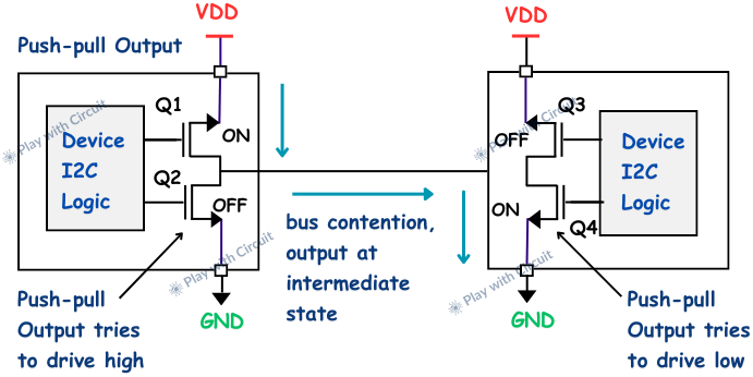
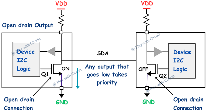
In open-drain output any device can pull the connection LOW at any time. In the below figure, NMOS Q1 is turned ON, hence device 1 pulls the bus to GND and NMOS Q2 is OFF, hence device 2 has released the bus. The line will be pulled to LOW without putting the bus in a destructive state as the bus is wired-AND connection.
I2C Protocol
Start Condition
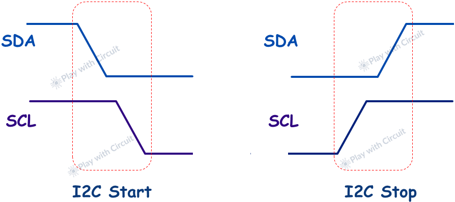
The controller sends the START condition to begin the communication. To do this, it first pulls the SDA LOW which means the line switches from a HIGH voltage level to a LOW voltage level when SCL is HIGH. Then it pulls the SCL LOW. It is a signal to all devices on the bus that a transmission is about to start.
Once the START condition is sent by the controller device, all target devices will become active even in sleep mode and wait to receive address bits.
Stop Condition
When the controller device has completed data transmission, it issues an I2C STOP condition. For this first the SCL switches from LOW to HIGH then SDA switches from LOW to HIGH when SCL is HIGH, this indicates that the communication is completed and the bus is released.
Repeated Start Condition
This is useful in multi-controller communication. When the STOP pulse is sent by a controller then it is a signal to another controller that the bus will go in idle state then after STOP condition another controller tries to control the I2C bus. However when the previous controller doesn’t want to lose control over the bus and wants to start a new communication, it sends another START pulse condition at the end of communication, this is known as repeated START condition.
Logic HIGH (1) and Logic LOW (0) in I2C Communication
In I2C, data is transmitted serially using a sequence of 0’s and 1’s. SDA is used to transfer the data bits while SCL is the serial clock that times the bit sequence.
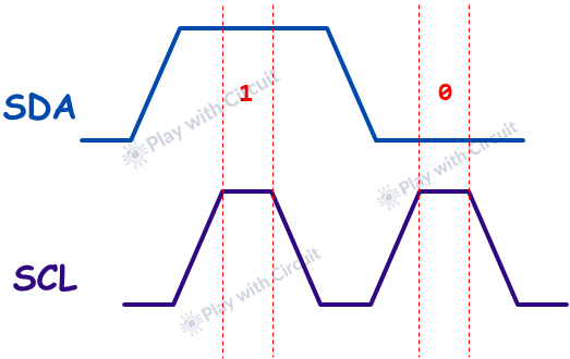
In the above figure, logic 1 is sent, when SDA pulls the line HIGH and logic 0 is sent when SDA pulls the line to 0. The 1’s (HIGH) and 0’s (LOW) are received only when SCL is HIGH.
The SDA does not change between the rising and falling edge of SCL. It only changes when SCL is LOW because if the SDA changes when SCL is HIGH, it is interpreted as a START or STOP condition.
I2C Communication Frames
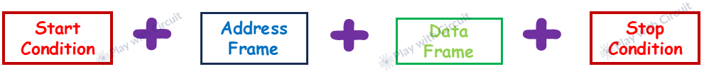
Address Frame
Each I2C target device on the bus has a unique address. When the controller device wants to send or receive data from a particular target device it uses this address. The I2C address frame consists of 7 address bits and 1 read/write bit.
The I2C address consists of 7 bits and can form 2^7 (or 128) unique addresses. While transmitting the address bits the MSB is transmitted first. Also, there are several reserved I2C addresses which limits the number of possible devices which we will discuss in coming sections.
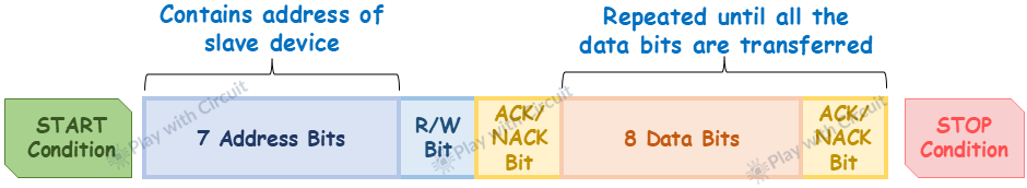
Read/Write Bit
If this read-write (R/W) bit is 0, the controller is sending the data to the target device. If this bit is 1, the controller is receiving the data from the target device.
ACK/NACK Bit
An ACK (Acknowledge) bit is used to verify whether the communication was successful. At the end of the address byte transmission, the target device pulls down (LOW) the SDA during the SCL pulse to indicate to the controller that the address was received. This indicates successful communication.
If this bit is HIGH, then no target device received the address and the communication was unsuccessful. This is known as a NACK.
This is a useful debugging tool. The absence of an ACK bit can indicate that the target device did not receive the proper I2C address or expected data for communication.
Data Frame
After the controller detects the ACK bit from the target device for the address frame, the I2C data frame is ready to be sent. It consists of 8 bits and transmitted with the Most Significant Bit (MSB) first. After the data frame is transferred, there is another ACK bit sent by the target device to verify that the data has been received successfully.
In cases where multiple frames are transmitted sequentially, each is followed by an ACK/NACK bit to be sent by the target to validate the transfer. When the data is received by the controller then ACK/NACK Bit needs to be sent by controller.
Reserved Addresses
As we have discussed earlier, in the I2C protocol, each device connected to the bus must have a unique address to enable the controller to identify which device to communicate with. The protocol uses 7-bit addressing. However, several addresses within this range are reserved for specific purposes.
These sets of reserved addresses are limited for use based on specific applications. These addresses have predefined functions and are they not assigned to devices.
The following table shows the set of these reserved addresses and their functions.
| Target Address | R/W Bit | Description |
|---|---|---|
| 000 0000 | 0 | General Call Address |
| 000 0000 | 1 | START Byte |
| 000 0001 | X | C-Bus Address |
| 000 0010 | X | Reserved for different bus format |
| 000 0011 | X | Reserved for future purposes |
| 000 01XX | X | Hs-mode controller code |
| 111 11XX | 1 | Device ID |
| 111 10XX | X | 10-bit target Address |
How I2C Communication Works?
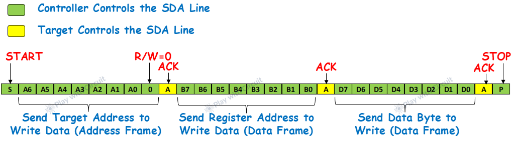
Writing Data to a Target
To write data the controller follows following steps:
-
Controller sends the START condition on the bus.
-
Controller sends the address frame containing target address with R/W bit set to 0 followed by Acknowledgement bit sent by target.
-
Now the controller sends the register address on which data is to be written followed by acknowledgement by target.
-
Now the controller sends the data byte followed by acknowledgement by target. Also controller can send multiple bytes followed by acknowledgement by target.
-
To terminate the communication controller sends the STOP condition.
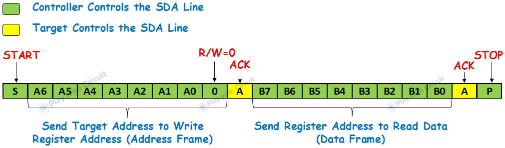
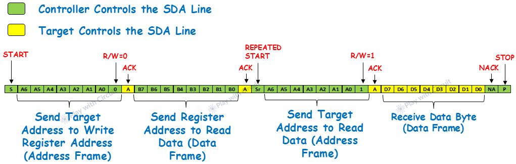
Reading Data from a Target Device
To read data the controller follows following steps:
- Controller sends the START condition on the bus.
- Controller sends the address frame containing target address with R/W bit set to 0 followed by Acknowledgement bit sent by target.
- Now the controller sends the register address on which data is to be written followed by acknowledgement by target.
- The next step can be done in two ways:
- Target stops the communication by sending STOP condition and then starts a new communication by sending START condition to read the data byte.
- Target stops the communication by sending STOP condition and then starts a new communication by sending START condition to read the data byte.
-
- Target can send a repeated start by sending a START condition to read the data byte.
- Target can send a repeated start by sending a START condition to read the data byte.
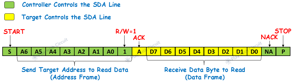
- Now the controller sends the address frame containing target address with R/W bit set to 1 followed by Acknowledgement bit sent by target. As soon as acknowledgement is received by controller it releases the SDA bus but will continue to supply the clock to target so that target can transmit the data, as the controller has now become receiver and target has now become the sender.
- Now the target sends the data byte followed by Acknowledgement by the controller. Also, the target can send multiple bytes followed by Acknowledgement by the controller.
- To terminate the communication, the controller can send a NACK bit when it receives the last byte or when it doesn’t want to receive further bytes followed by the STOP condition.
I2C Protocol Speed Modes
The I2C protocol has multiple speed modes for different applications. These modes define the maximum data rate at which communication can occur. Below are the details of each speed mode:
-
Standard Mode (Sm): This is the basic mode of I2C that supports data transfer rate up to 100 kilobits per second (kbps). It is suitable for low-speed communication. It is widely used and supported by almost all devices that use I2C.
-
Fast Mode (Fm): It is a faster version of the protocol that supports data transfer rate up to 400 kilobits per second. It can be used by the controller if the I2C bus capacitance and drive capability allow for the faster speed.
-
Fast Mode Plus (Fm+): It allows for communication as high as 1 megabit per second (Mbps). In this mode devices need drivers with extra strength to comply with the shorter rise and fall times necessary for higher speeds.
-
High-speed Mode (Hsm): This mode has a data rate up to 3.4 megabits per second (Mbps). In this mode controller device sends a specific controller code to the target device to initiate high-speed data transfer. This enables high-speed mode in the target device. It can also require an active pull-up on the communication lines to ensure reliable operation at such high speeds.
-
Ultra-Fast Mode (UFm): This is the fastest I2C mode available supporting data transfer rate up to 5 megabits per second (Mbps). It is write-only and omits certain features of I2C to achieve higher speeds.
The following table shows the maximum transmission rates for different I2C Modes:
| Mode | Maximum Speed |
|---|---|
| Standard Mode (Sm) | 100 kbps |
| Fast Mode (Fm) | 400 kbps |
| Fast Mode Plus (Fm+) | 1 Mbps |
| High-Speed Mode (Hsm) | 3.4 Mbps |
| Ultra-Fast Mode (UFm) | 5 Mbps |
Clock Synchronization and Arbitration
Clock Synchronization
In an I2C system there can be multiple controllers sharing the same bus. So there may be a situation when two or more controllers try to initiate communication and claim the bus at the same time. So proper synchronization is required to determine which controller can claim the bus.
In I2C communication clock synchronization is used to ensure that one controller controls the bus without disrupting communication. This is done using open-drain connections and a wired-AND logic on the SCL line.
In I2C bus, the SCL line follows a logical AND operation:
- If any controller pulls SCL LOW, the wired-AND connection is LOW.
- SCL will be HIGH only when both controllers release the open drain connection high.
Truth Table for Wired-AND Connection on SCL:
| Controller 1 | SCL Controller 2 | Resulting SCL |
|---|---|---|
| 0 | 0 | 0 |
| 0 | 1 | 0 |
| 1 | 0 | 0 |
| 1 | 1 | 1 |
This behaviour ensures that controllers cannot dominate the clock line and wait until other controllers release it.
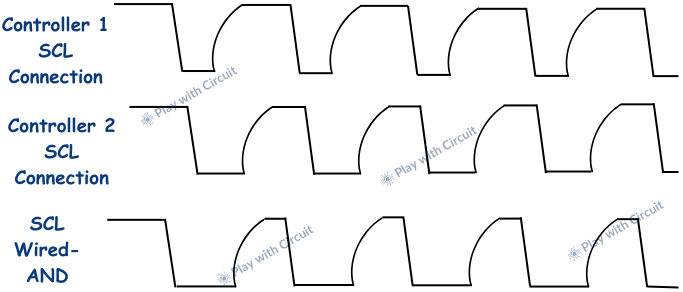
In the following figure, controller 1 initiates a START condition just before controller 2. Since controller 1 pulls the SCL line LOW first, the wired-AND connection causes SCL to pull down LOW.
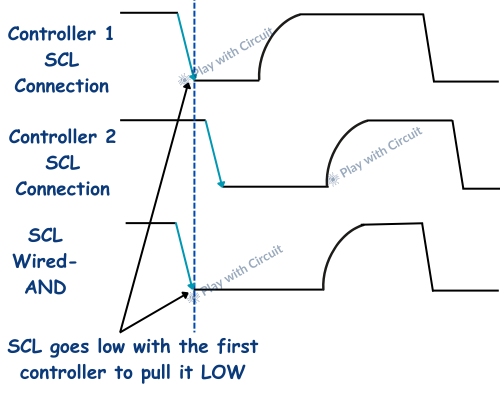
After sending the START condition, controller 1 releases the SCL line, allowing it to go high. However, controller 2 is still holding SCL LOW due to wired-AND connection. So the clock line will remain LOW until all controllers release it. If controller 1 wants SCL to go high, it must wait until controller 2 releases the SCL.
When multiple controllers are trying to claim for the bus, SCL will stay LOW for the longest time that any controller keeps it low. Only when all controllers release the SCL line can it go high, allowing the clock signal to continue. This ensures that all controllers on the I2C bus stay synchronized.
The final SCL generated is the wired-AND of individual SCL generated by different controllers. The following figure shows the SCL when both controllers release it.
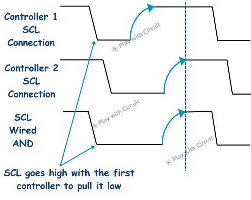
This clock synchronization works because each controller monitors SCL and checks if it matches the state controller expects and if it doesn’t match then changes the SCL as per the wired-AND output it gets at SCL line.
The SCL clock remains synchronized for all following clock pulses between the active controllers. The synchronization process continues throughout the communication, as shown in the following figure.
Bus Arbitration
After the SCL clocks are synchronized, arbitration takes place on the SDA line.
Both controllers send data on the SDA line to the target device. Like SCL, SDA is also a wired-AND connection, which means if one controller pulls it LOW, the line stays LOW. Following figure shows this arbitration process.
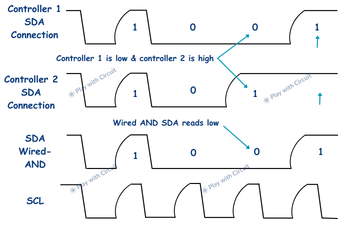
As shown in the above figure, both controller devices start the communication at the same time by sending a START signal. The first two bits of the data they sent are the same. However, when they send the third bits of the data, there is a difference as controller 1 sends a 0 while controller 2 sends a 1.
As both the controllers monitor SCL and SDA lines, the bus contention is found. Controller 2 notices that the line is LOW even though it sent 1. Hence to resolve this bus contention controller 2 releases the bus due to wired-AND result and lets controller 1 continue the data transmission. This process is called arbitration, and in this case, controller 1 wins.
Clock Stretching
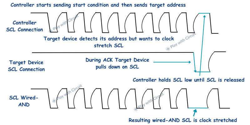
In I2C communication, the controller controls the clock, but in certain situations, the target device may slow down communication by holding the SCL line LOW. For example, if the target device needs more time to process a command or prepare data, it can hold the SCL line LOW during the ACK phase.
After the controller sends a byte of data, the target device holds down SCL longer with clock stretching. Thus, the controller is required to adjust the clock. The controller monitors SCL and is forced to extend the SCL pulse if SCL is still LOW after the controller has released the clock. Any SCL pulse can be clock-stretched by the target device.
Since I2C uses an open-drain (wired-AND) configuration, the controller is unable to force SCL HIGH while the target is holding it LOW.
The controller monitors the SCL line and waits until the target device releases it. Once SCL goes high, the controller resumes normal communication.
The following image shows an example of the target device clock stretching SCL.
Advantages of I2C Communication Protocol
- I2C requires only two wires, SCL (clock) and SDA (data), saving GPIO pins on microcontrollers and reducing wiring complexity.
- I2C supports multiple devices on the same bus, with up to 127 devices using 7-bit addressing.
- I2C follows an industry-standard protocol, ensuring compatibility across devices.
- I2C allows bidirectional communication on a single data line.
- In I2C, the acknowledgment mechanism ensures reliable data transmission and error detection.
- In I2C bus devices can be dynamically added or removed without restarting the system.
- Compatible with a wide range of platforms, including microcontrollers and FPGAs.
- Suitable for applications like sensor interfacing, memory devices, and real-time clocks.
- Ideal for embedded system applications.
Disadvantages of I2C Communication Protocol
While the I²C protocol is versatile and widely used, it has some limitations:
- Maximum speed (5 Mbps in Ultra-Fast Mode) is lower than some other communication protocols like SPI, which can exceed 10 Mbps.
- Since multiple devices share the same bus, there is a possibility of data collision, especially if multiple controllers are used.
- The pull-up resistors on the bus consume more power, especially at higher speeds, making I²C less power-efficient compared to some alternatives.
- Due to signal degradation, I²C is limited to short-distance communication, typically within a few meters.
- The communication sequence involves start/stop conditions, acknowledgments, and clock stretching, which can make implementation more complex than simpler protocols like UART.
- At higher speeds (Fast Mode Plus and beyond), maintaining signal integrity becomes challenging, often requiring stronger drivers and active pull-ups.
Copyright © 2025 Play with Circuit. All rights reserved.