
The LM324 is a widely used integrated circuit (IC) that can be used as comparators, making the LM324 a popular choice for comparator applications. It is commonly used in both analog and digital systems, providing a cost-effective and reliable solution for voltage comparison tasks.
In this article, we will understand how the LM324 can be used as a comparator, explore its pin configuration, working principle, basic comparator circuits, specifications, and real-world applications, including an over-temperature sensing circuit.
What is a Comparator?
A comparator is an electronic circuit that compares two input voltages and produces an output indicating which one is larger. It determines whether one voltage is greater than, less than, or equal to another voltage.
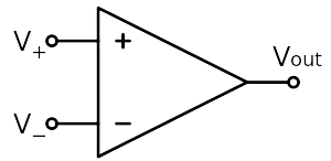
The basic operation of a comparator involves two input terminals: an inverting input (-) and a non-inverting input (+), and one output terminal. When the voltage at the non-inverting input is higher than the voltage at the inverting input, the output of the comparator typically goes to a high voltage level (often the positive supply voltage). Conversely, when the voltage at the inverting input is higher, the output typically goes to a low voltage level (often ground).
LM324 IC Overview
LM324 IC consists of four independent, high-gain operational amplifiers on a single chip. The op-amps inside the LM324 can compare two input voltages and provide a digital output based on the comparison result. When the voltage at the non-inverting input (+) is higher than the voltage at the inverting input (-), the output of the comparator will be high (logic 1). Conversely, when the voltage at the non-inverting input is lower than the voltage at the inverting input, the output will be low (logic 0).

| Pin | Function of the Pin |
|---|---|
| Pin 1 (OUTPUT 1) | Output of the 1st comparator |
| Pin 2 (INPUT 1-) | Inverting input of the 1st comparator |
| Pin 3 (INPUT 1+) | Non-inverting input of the 1st comparator |
| Pin 4 (VCC) | Positive supply voltage |
| Pin 5 (INPUT 2+) | Non-inverting input of the 2nd comparator |
| Pin 6 (INPUT 2-) | Inverting input of the 2nd comparator |
| Pin 7 (OUTPUT 2) | Output of the 2nd comparator |
| Pin 8 (OUTPUT 3) | Output of the 3rd comparator |
| Pin 9 (INPUT 3-) | Inverting input of the 3rd comparator |
| Pin 10 (INPUT 3+) | Non-inverting input of the 3rd comparator |
| Pin 11 (GND, VEE) | Ground or negative supply voltage |
| Pin 12 (INPUT 4+) | Non-inverting input of the 4th comparator |
| Pin 13 (INPUT 4-) | Inverting input of the 4th comparator |
| Pin 14 (OUTPUT 4) | Output of the 4th comparator |
Specifications of LM324 IC
- Supply Voltage Range (Single Supply): Typically operates from a single power supply voltage ranging from 3V to 32V.
- Supply Voltage Range (Dual Supply): Typically operates from dual power supply voltages ranging from ±1.5V to ±16V.
- Input Offset Voltage: Typically around 3 mV.
- Input Offset Current: Typically around 2 nA.
- Input Bias Current: Typically around 20 nA.
- Input Common Mode Voltage Range: Typically includes ground.
- Gain Bandwidth Product (GBP): Typically ranges from 1 MHz to 1.3 MHz.
- Input Impedance: High input impedance.
- Output Impedance: Low output impedance.
Basic Configuration of LM324 IC
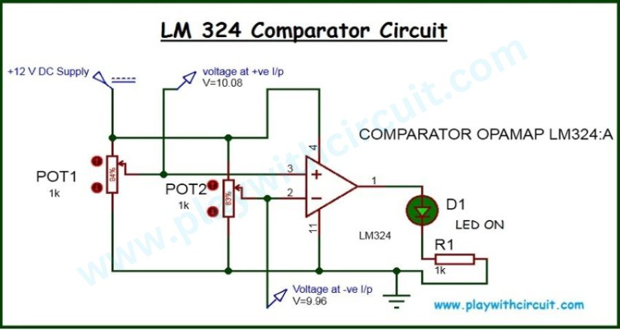
The following circuit demonstrates how the LM324 op-amp works as a comparator. In this configuration, the LM324 is powered using a single +12 V DC supply, where pin 4 is connected to the positive supply and pin 11 is connected to ground. One op-amp inside the LM324 IC is used to compare two voltages and produce a digital-like output that drives an LED indicator.
Two potentiometers, POT1 and POT2 (both 1 kΩ), are used in the circuit to generate variable voltages. These potentiometers act as voltage dividers, allowing the user to vary the voltages applied to the comparator inputs manually. POT1 is mainly used to generate a reference voltage, while POT2 generates the input voltage that is compared against this reference.
The non-inverting input (+) of the LM324 is connected to pin 3, while the inverting input (–) is connected to pin 2. The comparator works on a simple principle: when the voltage at the non-inverting input is greater than the voltage at the inverting input, the output of the comparator goes HIGH. Conversely, when the voltage at the inverting input is higher than the voltage at the non-inverting input, the output goes LOW. This fundamental rule governs the behavior of both circuit conditions shown in the images.
In the image shown below, the voltages at the comparator inputs change due to adjustment of the potentiometers. Here, the voltage at the non-inverting input remains around 10.08 V, while the voltage at the inverting input drops to approximately 9.96 V. In this case, the voltage at the positive input becomes greater than the voltage at the negative input. As a result, the comparator output switches to a HIGH state. The output voltage at pin 1 rises close to the supply voltage, forward-biasing the LED. Current now flows from the output pin through the LED and the series resistor R1 to ground, causing the LED to turn ON.
In the following image, the voltage at the non-inverting input (pin 3) is approximately 10.08 V, while the voltage at the inverting input (pin 2) is higher at around 11.04 V. Since the voltage at the negative input is greater than the voltage at the positive input, the LM324 output saturates toward ground. As a result, the output voltage at pin 1 is low, which means there is insufficient forward bias across the LED and the current-limiting resistor. Because no current flows through the LED, it remains turned OFF.
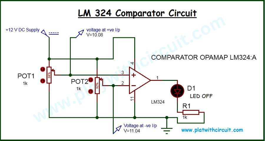
Here, the LED in this circuit acts as a visual indicator of the comparator output state, allowing you to easily understand whether the output is HIGH or LOW. The resistor R1, typically 1 kΩ, is connected in series with the LED to limit the current and protect the LED from damage. Without this resistor, excessive current could flow through the LED, potentially destroying it.
It is important to note that the LM324 output does not reach the full supply voltage when it goes HIGH. This is because the LM324 is not a rail-to-rail op-amp, and its output typically saturates about 1 to 1.5 V below the positive supply. Despite this limitation, the output voltage is still sufficient to drive an LED or a transistor in low-power applications.
LM324 IC based Over Temperature Sensing Circuit
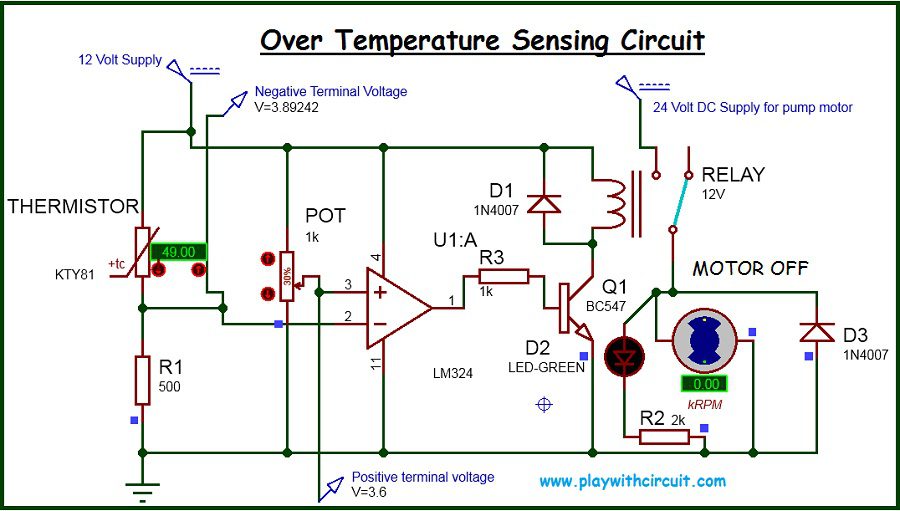
The above over-temperature sensing circuit demonstrates a practical, real-world application of the LM324 used as a comparator, where an electrical load such as a water pump motor is automatically controlled based on temperature. The circuit operates using a PTC thermistor (Positive Temperature Coefficient) KTY81. A PTC thermistor has the property that its resistance increases as temperature increases. This characteristic makes it suitable for over-temperature detection.
In this circuit, the LM324 is powered using a single 12 V DC supply. One of the internal op-amps of the LM324 is configured as a comparator. The comparator continuously compares two voltages: one derived from the thermistor (temperature-dependent voltage) and the other set using a potentiometer, which acts as a reference voltage corresponding to the temperature threshold.
The thermistor and resistor R1 together form a voltage divider. As the temperature increases, the resistance of the PTC thermistor increases, causing the voltage at the comparator input connected to the thermistor network to rise. The potentiometer (POT) is used to set the reference voltage corresponding to the desired switching temperature, which in this case is 50 °C. By adjusting the potentiometer, the we can calibrate the circuit so that the comparator switches exactly at the required temperature.
When the temperature is below 50 °C, the voltage at the non-inverting input (pin 3) of the LM324 is lower than the voltage at the inverting input (pin 2). Under this condition, the comparator output remains LOW. Since the output is low, no base current is supplied to the transistor Q1 (BC547). As a result, the transistor remains in the OFF state, the relay coil is not energized and the pump motor remains OFF as shown in the above image.
As the temperature rises and reaches 50 °C, the resistance of the thermistor increases further, which increases the voltage at the non-inverting input of the comparator. When this voltage becomes greater than the reference voltage at the inverting input, the LM324 comparator output switches to a HIGH state. This high output voltage is applied to the base of the BC547 transistor through the base resistor R3, providing sufficient base current to turn the transistor ON.
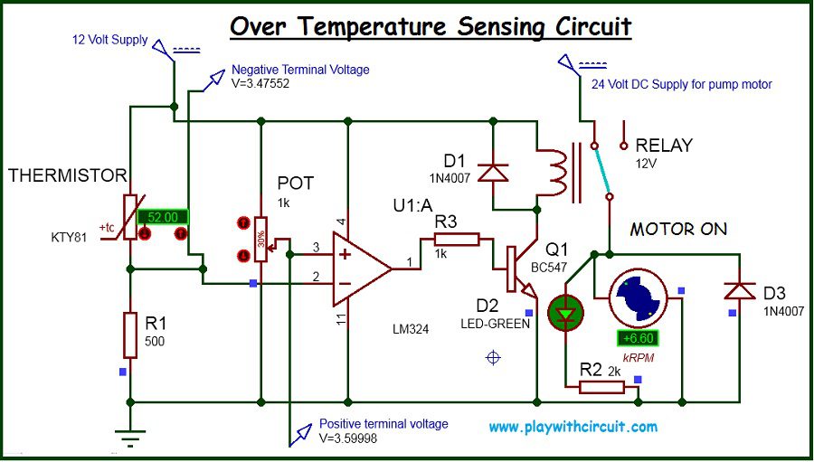
Here BC547 transistor is used as a switch. When the transistor turns ON, current flows from its collector to emitter, energizing the relay coil. Once the relay is activated, its contacts close and connect the 24 V DC supply to the pump motor, causing the motor to start running. The green LED (D2) also turns ON.
Diode D1 is connected across the relay coil and acts as a flyback diode. When the relay is switched OFF, the collapsing magnetic field of the coil generates a high-voltage spike that could damage the transistor or the LM324. D1 safely clamps this voltage spike, protecting the circuit components. Similarly, diode D3 provides protection across the motor by suppressing voltage transients generated due to the inductive nature of the motor.
When the temperature falls below the threshold again, the resistance of the thermistor decreases, reducing the voltage at the non-inverting input of the LM324. Once this voltage drops below the reference voltage, the comparator output returns to a LOW state. The transistor turns OFF, the relay de-energizes, and the pump motor stops running automatically.
Applications of LM324 IC
LM324 can be used in variety of applications which uses voltage comparisons as well as normal Op-amp Applications i.e., it can also be used in applications which uses UA741 IC. Some of its applications are mentioned below:
Voltage Comparators: The high gain and low input offset voltage of the LM324 make it suitable for voltage comparator circuits that are used in applications such as overvoltage protection, window detectors, and waveform generators.
Signal Conditioning: The LM324 can be used to condition signals from sensors such as temperature sensors, light sensors, and pressure sensors, by amplifying, filtering, or linearizing the output signal.
Active Filters: Its high gain-bandwidth product and low input offset voltage make the LM324 suitable for designing active filter circuits such as low-pass, high-pass, band-pass, and band-reject filters used in audio, communications, and instrumentation applications.
Voltage Followers: The LM324 can be configured as a voltage follower to provide isolation between the input and output signals, maintaining the same voltage level as the input signal with high input impedance and low output impedance.
Oscillators and Waveform Generators: The LM324 can be used in oscillator circuits to generate square, triangular, or sawtooth waveforms for various applications such as waveform synthesis, clock generation, and frequency modulation.
Power Supply Circuits: The LM324 can be used in voltage regulation circuits, voltage reference circuits, and current sensing circuits in power supply designs to improve stability, efficiency, and protection.
Voltage-Controlled Oscillators (VCOs): Its high gain and low input offset voltage make the LM324 suitable for designing VCOs used in frequency modulation and frequency synthesizers.
Control and Protection Circuits: LM324 is widely used in control systems such as temperature controllers, battery monitors, motor protection circuits, and relay drivers.
Advantages of LM324 IC
-
Operates on a single power supply, eliminating the need for dual supply voltages
-
Contains four op-amps in one IC, reducing component count and PCB space
-
Input common-mode range includes ground, making it ideal for sensor interfacing
-
Low power consumption, suitable for battery-powered applications
-
High input impedance, allowing direct connection to sensors
-
Low cost and widely available
Limitations of LM324 IC
-
Not a rail-to-rail op-amp, output does not reach full supply voltage
-
Low slew rate and bandwidth, unsuitable for high-speed applications
-
No built-in hysteresis when used as a comparator
-
Output saturation causes slow switching in comparator mode
-
Cannot directly drive high-current loads such as motors or relays
-
Not suitable for precision or high-frequency signal processing
FAQ’S
What is the meaning of LM in LM324?
LM stands for linear monolithic, referring to the analog components integrated into a single piece of silicon.
What is the voltage gain of LM324?
The LM324 operational amplifier (op-amp) has a voltage gain of 100x.
What is the voltage limit for LM324?
The LM324 typically has a voltage supply range of around 3V to 32V. It can operate with dual power supplies (±1.5 V to ±16 V) or a single power supply, making it versatile for various electronic applications.
What is the function of LM324 IC?
The LM324 IC is a quad operational amplifier that is used to amplify analog signals, compare voltages, and process sensor outputs. It can operate on a single power supply, making it suitable for applications such as voltage comparators, signal conditioning, active filters, oscillators, and control circuits.


