
In the rapidly expanding world of IoT, sending data wirelessly across long distances—without high power consumption has become more important than ever. Wi-Fi, Bluetooth, cellular networks, and RF modules are some of the most widely used wireless technologies. However each of these technologies comes with limitations. For instance, Wi-Fi and Bluetooth drain battery quickly, while RF modules require high power to transmit over long distances. Cellular networks cover wide areas but are expensive and power-hungry, making them unsuitable for IoT devices.
This is where LoRa technology comes into play. It enables devices to transmit data over several kilometers while consuming very little power, making it ideal for IoT applications. In this tutorial, we will learn about the RYLR999 Module and how to interface it with Arduino. We’ll show you how to create a simple communication system using LoRa transceiver devices.
What is LoRa?
LoRa, short for Long Range, is a wireless communication technology developed by Semtech. As the name suggests, it can send data over longer distances than technologies such as Wi-Fi or Bluetooth, which are limited to short distances. This makes it suitable for IoT devices, which usually operate on small batteries and generate low amounts of data, such as temperature readings, humidity values, water levels, or simple alerts.
LoRa can transmit bi-directional data over long range—typically 15 to 20 kilometers in open environments. LoRa communication uses license-free ISM bands, typically 433 MHz, 868 MHz, or 915 MHz, which are well-suited for long-range, low-power wireless transmission. For applications requiring higher data throughput, LoRa can also operate in the 2.4 GHz band, though this comes with reduced range.
How does LoRa Technology Work?
LoRa works at the physical layer of wireless communication and focuses on how data is transmitted and received over radio. When a device needs to send data, the digital information is passed from the microcontroller to the LoRa radio transceiver. The transceiver then modulates this data using Chirp Spread Spectrum (CSS) modulation technique, where the signal is encoded as frequency-swept chirps.
These chirp signals spread the data across a wider bandwidth, which significantly improves receiver sensitivity and resistance to noise and interference. As a result, LoRa receivers can receive signals even when they are extremely weak, allowing communication over several kilometers while using very low transmission power. On the receiving side, the LoRa radio demodulates the chirp signal and converts it back into digital data for the microcontroller to process.
LoRa operates at low data rates, transmitting small packets of data rather than continuous streams. This trade-off between data rate and range allows devices to remain in sleep mode most of the time, enabling long battery life. LoRa itself handles only the radio communication; higher-level networking and cloud connectivity are implemented using protocols such as LoRaWAN.
❕Note
LoRa is not suitable for high-bandwidth applications such as video, audio, or large file transmission. Instead, it is used in applications where devices need to send small messages—sensor readings, alarm signals, control commands, or GPS coordinates.
Introduction to RYLR999 Module
The RYLR999 Lite is a powerful long-range wireless communication module developed by REYAX Technology. What makes this module unique is that it combines LoRa communication at 868/915 MHz with 2.4 GHz Bluetooth Low Energy (BLE) inside a single compact transceiver. It provides separate UART interfaces for BLE and LoRa, enabling independent communication channels for short-range and long-range wireless operations.
The BLE UART interface handles data exchange with smartphones, BLE modules, or BLE-enabled microcontrollers. The LoRa UART interface is responsible for transmitting and receiving LoRa packets.
Users can configure LoRa addresses, Network IDs, frequencies, and modulation parameters using AT commands. When the module receives a TX command, it modulates the data using LoRa’s CSS technique and transmits it across long distances. When another RYLR999 receives the data, it demodulates the packet and outputs it through its UART interface.
One of the most innovative capabilities of the RYLR999 is its ability to act as a BLE-to-LoRa converter. This makes it possible for smartphone applications—normally limited to a few meters of communication—to indirectly transmit messages across several kilometers using LoRa.
Features of RYLR999
Power Supply
- 4.75V to 5.25V supply voltage
- 3.3V digital I/O levels
BLE Specifications
- Output power: +20 dBm
- RF Frequency Range: 2400-2483.5 MHz
- Transmit Mode current: 190 mA
- Advertising Current: 17 mA
- Frequency Accuracy: ±20 ppm
LoRa Specifications
- Output power: +30 dBm (1 Watt)
- Frequency range: 820-960 MHz
- Transmit current: 650 mA
- Receive current: 15.5 mA
- Sleep mode current: 1.25 mA
- Deep sleep mode current: 18.2 uA
- Operating Temperature: -40 to +85 ˚C
For more details, please refer to the datasheet provided below.
RYLR999 Pinout
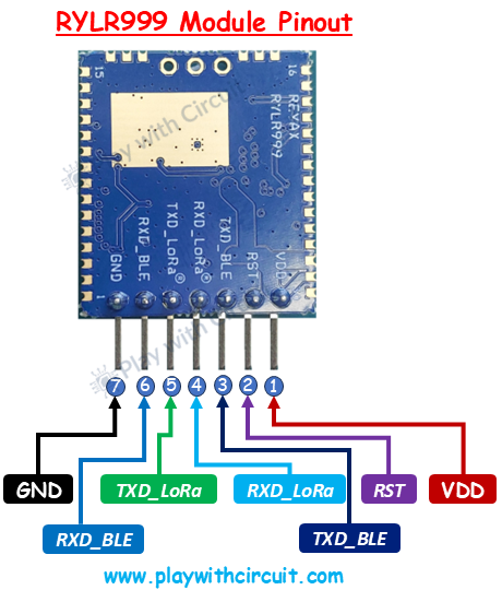
VDD (Pin 1) The VDD pin is the power supply pin. The module must be powered with a regulated 5V supply, typically between 4.75V and 5.25V.
RST (Pin 2) The RST pin is a low-trigger reset pin. To reset the module this pin is pulled to logic LOW.
TXD_BLE (Pin 3) This is a BLE UART Transmit Pin, which acts as the data output pin. This pin becomes crucial when using the module for BLE-to-LoRa bridging. In such scenarios, the TXD_BLE pin is connected internally (or via jumper) to the RXD_LoRa pin, enabling any data transmitted by a BLE device to be forwarded into the LoRa communication path.
RXD_LoRa (Pin 4) This Pin is used for receiving data over the LoRa UART interface. It accepts AT commands from a microcontroller, PC terminal, or BLE subsystem. Any LoRa transmission instructions, parameter changes, frequency settings, or network configurations sent to the module must enter through this pin. The pin runs at 3.3V logic levels.
TXD_LoRa (Pin 5) This is a LoRa UART Transmit Pin which is the primary output pin for all LoRa-related communication. When the RYLR999 receives data, it outputs the received packets, along with status messages through this pin. All AT command responses from the LoRa subsystem—including success notifications and error messages are also transmitted through this pin.
RXD_BLE (Pin 6) This pin receives data intended for the BLE subsystem. Any command that a microcontroller or PC wants to send over BLE must be written to this pin.
GND (Pin 7) This is the Ground pin. This pin must be connected to the ground of the microcontroller and power supply.
Interfacing RYLR999 Module with Arduino UNO
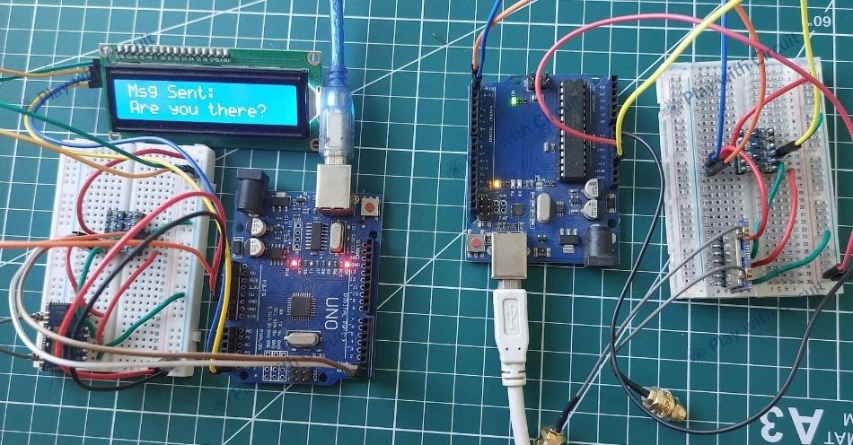
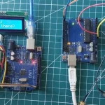
Now that we have a complete understanding of RYLR999 Module, we will set up a simple point-to-point wireless communication setup using two Arduino boards. One Arduino will act as the initiator, responsible for sending a message, while the second Arduino will act as the responder, which waits for incoming data and replies accordingly. The initiator periodically transmits the message “Are you there?”, and upon receiving this request, the responder sends back a confirmation message “Yes”. This two-way exchange helps verify successful communication between the two LoRa modules and demonstrates how data can be transmitted and received using AT commands. Before moving on to the code, we will first understand how the modules are wired to the Arduino on both the initiator and responder sides.
Hardware Requirement
| Components | Quantity | Remarks | Where to Buy |
|---|---|---|---|
| Arduino UNO R3 | 1 | Revision R3 | Amazon |
| LCD 16x2 | 1 | I2C support | Amazon |
| Jumper Wires | Multiple | For Arduino and LCD connections | Amazon |
| USB Cable Type A to B | 1 | for programming Arduino UNO | Amazon |
| 12V Supply Adapter | 1 | For providing power to Arduino | Amazon |
| 5V Voltage Shifter Module | 1 | for voltage level shifting | Amazon |
| RYLR999 Module | 2 | For interfacing with Arduino | Amazon |
Software Requirement
- Arduino IDE, Version 2.3.4 or above installed on your PC.
- LiquidCrystal_I2C Library by Frank de Brabander V 1.1.2
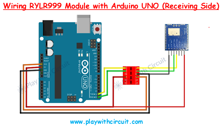
Wiring Connections for the Initiator Setup
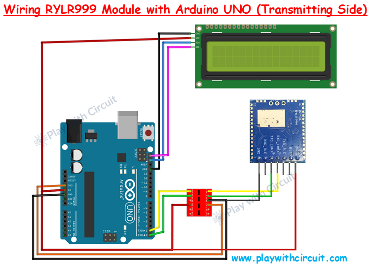
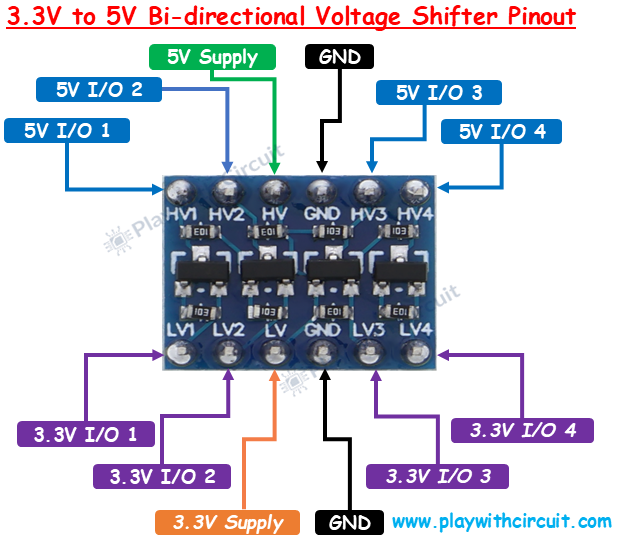
In the initiator circuit, the Arduino UNO sends LoRa commands to the RYLR999 module and displays the transmission status on a 16×2 LCD. In the above wiring diagram, VDD pin of the RYLR999 is connected to the 5V output of the Arduino UNO. The GND pin of the module is connected to the Arduino’s GND. The TXD pin of LoRa module is connected to the LV1 pin of Voltage shifter and the corresponding HV1 output of voltage shifter module is connected to the Arduino’s Rx pin, while the TXD pin of Arduino is connected to the HV2 pin of voltage shifter and corresponding LV2 output is connected to RxD LoRa pin. The 5V pin of Arduino is connected to the HV pin of voltage shifter and 3.3V pin of Arduino is connected to LV pin of the voltage shifter module. These power connections are important to make voltage shifters work.
The pinout of voltage shifter module is given below:
The connections between Arduino Uno and RYLR999 Module are as follows:
| Arduino UNO Pin | RYLR999 Pin |
|---|---|
| 5V | VDD |
| GND | GND |
| Rx | TXD_LoRa(via voltage shifter) |
| Tx | RXD_LoRa( via voltage shifter) |
The wiring of the I2C LCD with Arduino is simple. Connect the Vcc and GND pins of I2C LCD with the Vcc and GND pins of the Arduino. SCL(clock) and SDA(data) pins of I2C LCD are connected to SCL and SDA pins of Arduino.
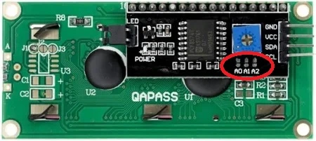
SCL and SDA pins are the same as pins A5 and A4 Analog input pins of Arduino where pink and blue wires are connected with LCD. These header pins are also connected to A5 and A4 pins of Arduino.
Make sure A0, A1, A2 address jumpers are not shorted when using I2C LCD. As in code we will be using Address 0x27 for the I2C LCD which will only be formed when these jumpers are not shorted in the I2C LCD.
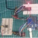
Wiring Connections for the Responder Setup
The responder setup is relatively simpler because no LCD is used. Here, the Arduino continuously listens for incoming LoRa messages from the initiator through the RYLR999 module and responds accordingly. Apart from the LCD connections, the wiring remains the same as the initiator setup.
Arduino Code for Initiator Setup
This code demonstrates a basic two-way wireless communication between two Arduino boards using the RYLR999 LoRa module. One Arduino sends the message “Are you there?” to the other Arduino, which listens for the request and replies back. The reply is displayed in real time on an I2C LCD.
/*
Code to send “Are you there?” from one Arduino to another Arduino using RLYR999 Module
and receive reply and display complete communication on I2C LCD by platwithcircuit.com
*/

#include <LiquidCrystal_I2C.h>

#define REPLY_TIMEOUT_IN_MS 300
#define REPLY_END_CHAR '\n'
#define MODULE_ADDRESS 0
#define RECEIVERS_ADDRESS 1
#define MIN_CHAR_TO_RCV 1
#define WAIT_FOR_RECIVERS_REPLY 3000
#define DELAY_BW_REPS 1000
// Init LCD at 0x27, 16x2
LiquidCrystal_I2C lcd(0x27, 16, 2);

void setup() {
  boolean boRetVal = false;
  // begin serial communication at baud 115200,n,8,1
  // to communicate with the RF module
  Serial.begin(115200);
  // initialize the LCD
  lcd.init();
  // Turn ON the Backlight
  lcd.backlight();
  // Clear the display buffer
  lcd.clear();

  flushBuffer();  // clear rx data

  // Reset settings to factory defaults
  boRetVal = boRestoreFactoryDefaults();

  // setting the address if reset successfully
  if (boRetVal == true) {
    flushBuffer();  // clear rx data
    boRetVal = boSetAddress();
  }

  if (boRetVal == true) {
    lcd.clear();
    lcd.setCursor(0, 0);
    lcd.print("Module Init");
    lcd.setCursor(0, 1);
    lcd.print("Successful");
    delay(1000);
  } else {
    lcd.clear();
    lcd.setCursor(0, 0);
    lcd.print("Module Init");
    lcd.setCursor(0, 1);
    lcd.print("Failed");
    while (1)
      ;
  }
}

void loop() {
  String request = "Are you there?";
  String expected_reply = "Yes";
  bool boRetVal = false;

  flushBuffer();  // clear rx data
  // transmits String named request
  boRetVal = boSendData(request);
  if (boRetVal == true) {
    // Displaying Sent Msg
    lcd.clear();
    lcd.setCursor(0, 0);
    lcd.print("Msg Sent:");
    lcd.setCursor(0, 1);
    lcd.print(request);
    delay(1000);
    boRetVal = chkReply(expected_reply, REPLY_END_CHAR, WAIT_FOR_RECIVERS_REPLY);

    if (boRetVal == true) {
      // Displaying received Msg
      lcd.clear();
      lcd.setCursor(0, 0);
      lcd.print("Msg Received:");
      lcd.setCursor(0, 1);
      lcd.print(expected_reply);
    } else {
      lcd.clear();
      lcd.setCursor(0, 0);
      lcd.print("No reply received.");
    }
  } else {
    // Displaying Failed Msg
    lcd.clear();
    lcd.setCursor(0, 0);
    lcd.print("Msg Sending");
    lcd.setCursor(0, 1);
    lcd.print("Failed");
  }

  delay(DELAY_BW_REPS);  // wait before sending again
}

void sendCrLf(void) {
  Serial.write(0x0D);  // Carriage Return
  Serial.write(0x0A);  // Line Feed
}

void flushBuffer(void) {
  while (Serial.available() > 0) {
    Serial.read();
  }
}

bool chkReply(String chkString, char receiveUntil, unsigned int timeout) {
  String receivedString;       // save received data in this string object
  bool boReturnValue = false;  // function's return value

  // wait for reply
  do {
    timeout--;
    delay(1);  // delay of 1 ms
  } while ((Serial.available() < MIN_CHAR_TO_RCV) && (timeout > 0));

  if (timeout) {
    // if timeout is left then a reply is received check for the string in the reply
    receivedString = Serial.readStringUntil(receiveUntil);
    if (receivedString.indexOf(chkString) != -1) {
      boReturnValue = true;
    } else {
      boReturnValue = false;
    }
  } else {
    boReturnValue = false;
  }

  // return result
  return boReturnValue;
}

bool boRestoreFactoryDefaults(void) {
  const char factoryDefaultCmd[] = "AT+FACTORY";  // command to be sent
  bool boReturnValue = false;                     // function's return value
  char downCounter = 100;                         // Down counter to wait for reply
  String receivedString;                          // save received data in this string object

  String chkRcvString1 = "+FACTORY";
  String chkRcvString2 = "+READY";

  // send command
  Serial.print(factoryDefaultCmd);
  sendCrLf();

  // check first string in reply
  boReturnValue = chkReply(chkRcvString1, REPLY_END_CHAR, REPLY_TIMEOUT_IN_MS);
  if (boReturnValue == true) {
    // check second string in reply
    boReturnValue = chkReply(chkRcvString2, REPLY_END_CHAR, REPLY_TIMEOUT_IN_MS);
  }

  // return result
  return boReturnValue;
}

bool boSetAddress(void) {
  const char setAddressCmd[] = "AT+ADDRESS=";  // command to be sent
  bool boReturnValue = false;                  // function's return value
  String chkRcvString = "+OK";

  // send command
  Serial.print(setAddressCmd);
  Serial.print(MODULE_ADDRESS);
  sendCrLf();

  // check reply
  boReturnValue = chkReply(chkRcvString, REPLY_END_CHAR, REPLY_TIMEOUT_IN_MS);

  // return result
  return boReturnValue;
}

bool boSendData(String data) {
  const char sendDataCmd[] = "AT+SEND=";  // command to be sent
  bool boReturnValue = false;             // function's return value
  String chkRcvString = "+OK";

  // send command
  Serial.print(sendDataCmd);
  Serial.print(RECEIVERS_ADDRESS);
  Serial.print(',');
  Serial.print(data.length());
  Serial.print(',');
  Serial.print(data);
  sendCrLf();

  // check reply
  boReturnValue = chkReply(chkRcvString, REPLY_END_CHAR, REPLY_TIMEOUT_IN_MS);

  // return result
  return boReturnValue;
}
Code Explanation
The sketch begins by including the library LiquidCrystal_I2C.h, which allows us to control the I2C LCD display.
#include <LiquidCrystal_I2C.h>Now we define constants. First, we set the timeout for replies, the end character for incoming messages, and the module addresses. The initiator module has address 0 and the receiver (responder) has address 1. We also define how many characters we need before reading the serial buffer and how long we should wait before sending the next message.
#define REPLY_TIMEOUT_IN_MS 300
#define REPLY_END_CHAR '\n'
#define MODULE_ADDRESS 0
#define RECEIVERS_ADDRESS 1
#define MIN_CHAR_TO_RCV 1
#define WAIT_FOR_RECIVERS_REPLY 3000
#define DELAY_BW_REPS 1000
Now we create an LCD object using the I2C address 0x27 with a 16×2 character display.
LiquidCrystal_I2C lcd(0x27, 16, 2);In the setup function, we first define a boolean variable, boRetVal, which will store the success or failure status of certain setup operations. Then we start serial communication at 115200 baud, which is the baud rate used by the RYLR999 module. Then we initialize the LCD, turn on the backlight, and clear the display. At this point, both communication interfaces (Serial and LCD) are ready.
void setup() {
  boolean boRetVal = false;
  // begin serial communication at baud 115200,n,8,1
  // to communicate with the RF module
  Serial.begin(115200);
  // initialize the LCD
  lcd.init();
  // Turn ON the Backlight
  lcd.backlight();
  // Clear the display buffer
  lcd.clear();
Before sending any commands to the module, we clear the serial buffer. This ensures that no old or leftover data interferes with the new commands or replies. Next we reset the LoRa module back to the factory setting.
 flushBuffer();  // clear rx data

  // Reset settings to factory defaults
  boRetVal = boRestoreFactoryDefaults();
Next we call boSetAddress() to set the device address to the value we defined earlier (MODULE_ADDRESS, which is 0). Every LoRa node in a point-to-point setup must have a unique address so that messages reach the correct destination.
// setting the address if reset successfully
  if (boRetVal == true) {
    flushBuffer();  // clear rx data
    boRetVal = boSetAddress();
  }
Next, we check whether initialization was successful. If it was, we show “Module Init Successful” on the LCD. If any step fails, we show “Module Init Failed” and stop the program using while(1);. This prevents us from running the loop with a misconfigured module.
if (boRetVal == true) {
  lcd.clear();
  lcd.setCursor(0, 0);
  lcd.print("Module Init");
  lcd.setCursor(0, 1);
  lcd.print("Successful");
  delay(1000);
} else {
  lcd.clear();
  lcd.setCursor(0, 0);
  lcd.print("Module Init");
  lcd.setCursor(0, 1);
  lcd.print("Failed");
  while (1);
}
In the loop function, we define the outgoing message and the expected reply. The message “Are you there?” will be sent, and we expect “Yes” in return. We also define a boolean variable to store the success status of sending and receiving.
void loop() {
  String request = "Are you there?";
  String expected_reply = "Yes";
  bool boRetVal = false;
Next, we call flushBuffer() to clear any previously received data from the serial buffer. Next, we send the message stored in the request string using the boSendData() function. The return value of this function is stored in boRetVal, which tells us whether the module successfully accepted the send command.
If the message is sent successfully, we clear the LCD and display the text “Msg Sent:” on the first line, followed by the actual message on the second line. A short delay is added so the message remains visible on the LCD.
flushBuffer();  // clear rx data
  // transmits String named request
  boRetVal = boSendData(request);
  if (boRetVal == true) {
    // Displaying Sent Msg
    lcd.clear();
    lcd.setCursor(0, 0);
    lcd.print("Msg Sent:");
    lcd.setCursor(0, 1);
    lcd.print(request);
    delay(1000);
After sending the message, the Arduino waits for a response from the responder by calling the chkReply() function. This function listens for incoming data for a predefined time and checks whether the received message contains the expected reply.
boRetVal = chkReply(expected_reply, REPLY_END_CHAR, WAIT_FOR_RECIVERS_REPLY);We now check the value of boRetVal to determine whether a reply was received from the responder. If the value is true, it means the expected reply was successfully detected. In this case, we clear the LCD and display “Msg Received:” on the first line, followed by the received reply on the second line. This confirms that communication between the initiator and responder is working correctly.
If boRetVal is false, it means no valid reply was received. In this situation, we clear the LCD and display “No reply received.” This helps the user identify communication issues such as incorrect wiring, mismatched addresses, or signal problems.
If the code reaches the else block, it indicates that the message itself could not be sent successfully in the first place. This happens when the RYLR999 module does not acknowledge the send command. In such cases, we clear the LCD and display “Msg Sending Failed” to indicate that transmission did not occur. Finally, we introduce a delay before repeating the process.
if (boRetVal == true) {
      // Displaying received Msg
      lcd.clear();
      lcd.setCursor(0, 0);
      lcd.print("Msg Received:");
      lcd.setCursor(0, 1);
      lcd.print(expected_reply);
    } else {
      lcd.clear();
      lcd.setCursor(0, 0);
      lcd.print("No reply received.");
    }
  } else {
    // Displaying Failed Msg
    lcd.clear();
    lcd.setCursor(0, 0);
    lcd.print("Msg Sending");
    lcd.setCursor(0, 1);
    lcd.print("Failed");
  }

  delay(DELAY_BW_REPS);  // wait before sending again
}
sendCrLf function is used to send a carriage return (CR) and line feed (LF) after every AT command sent to the RYLR999 module. The LoRa module expects each AT command to end with these two characters in order to recognize and execute the command correctly.
void sendCrLf(void) {
  Serial.write(0x0D);  // Carriage Return
  Serial.write(0x0A);  // Line Feed
}
The flushBuffer function keeps reading and discarding bytes until nothing is left. It cleans up the input buffer to avoid reading old or partial messages.
void flushBuffer(void) {
  while (Serial.available() > 0) {
    Serial.read();
  }
}
The chkReply function is used to check whether a specific reply is received from the LoRa module within a given time limit. It waits for incoming serial data until either at least one character is available or the timeout expires. If data arrives before the timeout, the function reads the incoming message until the specified end character and searches for the expected string inside it. If the expected text is found, the function returns true; otherwise, it returns false. This helps verify successful communication while avoiding infinite waiting when no response is received.
bool chkReply(String chkString, char receiveUntil, unsigned int timeout) {
  String receivedString;       // save received data in this string object
  bool boReturnValue = false;  // function's return value

  // wait for reply
  do {
    timeout--;
    delay(1);  // delay of 1 ms
  } while ((Serial.available() < MIN_CHAR_TO_RCV) && (timeout > 0));

  if (timeout) {
    // if timeout is left then a reply is received check for the string in the reply
    receivedString = Serial.readStringUntil(receiveUntil);
    if (receivedString.indexOf(chkString) != -1) {
      boReturnValue = true;
    } else {
      boReturnValue = false;
    }
  } else {
    boReturnValue = false;
  }

  // return result
  return boReturnValue;
}
This function resets the RYLR999 module to its factory default settings using the AT+FACTORY command. After sending the command, it waits for two confirmation responses from the module: first +FACTORY, indicating that the reset command was accepted, and then +READY, confirming that the module has completed the reset process and is ready to operate. The function returns true only if both responses are received within the specified timeout; otherwise, it returns false. This ensures that the module starts from a known and stable configuration before further setup.
bool boRestoreFactoryDefaults(void) {
  const char factoryDefaultCmd[] = "AT+FACTORY";  // command to be sent
  bool boReturnValue = false;                     // function's return value
  char downCounter = 100;                         // Down counter to wait for reply
  String receivedString;                          // save received data in this string object

  String chkRcvString1 = "+FACTORY";
  String chkRcvString2 = "+READY";

  // send command
  Serial.print(factoryDefaultCmd);
  sendCrLf();

  // check first string in reply
  boReturnValue = chkReply(chkRcvString1, REPLY_END_CHAR, REPLY_TIMEOUT_IN_MS);
  if (boReturnValue == true) {
    // check second string in reply
    boReturnValue = chkReply(chkRcvString2, REPLY_END_CHAR, REPLY_TIMEOUT_IN_MS);
  }

  // return result
  return boReturnValue;
}
This function sets a unique communication address for the Lora module by sending the AT+ADDRESS command along with the predefined module address. After sending the command, it waits for the +OK response from the module to confirm that the address has been configured successfully. Finally, the function returns true if the address was set successfully, otherwise it returns false.
bool boSetAddress(void) {
  const char setAddressCmd[] = "AT+ADDRESS=";  // command to be sent
  bool boReturnValue = false;                  // function's return value
  String chkRcvString = "+OK";

  // send command
  Serial.print(setAddressCmd);
  Serial.print(MODULE_ADDRESS);
  sendCrLf();

  // check reply
  boReturnValue = chkReply(chkRcvString, REPLY_END_CHAR, REPLY_TIMEOUT_IN_MS);

  // return result
  return boReturnValue;
}
This function sends data from the Arduino to another LoRa node using the RYLR999 module. It constructs the AT+SEND command by specifying the receiver’s address, the length of the data, and the actual message content, and then transmits this command over the Serial interface. After sending the command, the function waits for the module’s response and checks for the +OK confirmation, which indicates that the data was accepted for transmission.
bool boSendData(String data) {
  const char sendDataCmd[] = "AT+SEND=";  // command to be sent
  bool boReturnValue = false;             // function's return value
  String chkRcvString = "+OK";

  // send command
  Serial.print(sendDataCmd);
  Serial.print(RECEIVERS_ADDRESS);
  Serial.print(',');
  Serial.print(data.length());
  Serial.print(',');
  Serial.print(data);
  sendCrLf();

  // check reply
  boReturnValue = chkReply(chkRcvString, REPLY_END_CHAR, REPLY_TIMEOUT_IN_MS);

  // return result
  return boReturnValue;
}
Arduino Code for Responder Setup
This code is written for the responder Arduino that continuously listens for incoming messages from another Arduino using the RYLR999 LoRa module. When the message “Are you there?” is received, the Arduino sends back a confirmation reply “Yes”. This confirms that the wireless link between both RYLR999 modules is working correctly.
/*
Code to receive “Are you there?” from one Arduino to another Arduino using RLYR999 Module
and send "Yes" in reply by platwithcircuit.com
*/

#include <LiquidCrystal_I2C.h>

#define REPLY_TIMEOUT_IN_MS 300
#define REPLY_END_CHAR '\n'
#define MODULE_ADDRESS 1
#define RECEIVERS_ADDRESS 0
#define MIN_CHAR_TO_RCV 1
#define WAIT_FOR_REQUEST 3000

void setup() {
  boolean boRetVal = false;
  // begin serial communication at baud 115200,n,8,1
  // to communicate with the RF module
  Serial.begin(115200);

  delay(1000);

  flushBuffer();  // clear rx data

  // Reset settings to factory defaults
  boRetVal = boRestoreFactoryDefaults();

  // setting the address if reset successfully
  if (boRetVal == true) {
    flushBuffer();  // clear rx data
    boRetVal = boSetAddress();
  }

  if (boRetVal != true) {
    Serial.print("\n\rModule Init");
    Serial.print("Failed");
    while (1)
      ;
  }
}

void loop() {
  String request = "Are you there?";
  String expected_reply = "Yes";
  bool boRetVal = false;

  // check string sent by Initiator
  boRetVal = chkReply(request, REPLY_END_CHAR, WAIT_FOR_REQUEST);

  if (boRetVal == true) {
    boSendData(expected_reply);
  }
}

void sendCrLf(void) {
  Serial.write(0x0D);  // Carriage Return
  Serial.write(0x0A);  // Line Feed
}

void flushBuffer(void) {
  while (Serial.available() > 0) {
    Serial.read();
  }
}

bool chkReply(String chkString, char receiveUntil, unsigned int timeout) {
  String receivedString;       // save received data in this string object
  bool boReturnValue = false;  // function's return value

  // wait for reply
  do {
    timeout--;
    delay(1);  // delay of 1 ms
  } while ((Serial.available() < MIN_CHAR_TO_RCV) && (timeout > 0));

  if (timeout) {
    // if timeout is left then a reply is received check for the string in the reply
    receivedString = Serial.readStringUntil(receiveUntil);
    if (receivedString.indexOf(chkString) != -1) {
      boReturnValue = true;
    } else {
      boReturnValue = false;
    }
  } else {
    boReturnValue = false;
  }

  // return result
  return boReturnValue;
}

bool boRestoreFactoryDefaults(void) {
  const char factoryDefaultCmd[] = "AT+FACTORY";  // command to be sent
  bool boReturnValue = false;                     // function's return value
  char downCounter = 100;                         // Down counter to wait for reply
  String receivedString;                          // save received data in this string object

  String chkRcvString1 = "+FACTORY";
  String chkRcvString2 = "+READY";


  // send command
  Serial.print(factoryDefaultCmd);
  sendCrLf();

  // check first string in reply
  boReturnValue = chkReply(chkRcvString1, REPLY_END_CHAR, REPLY_TIMEOUT_IN_MS);
  if (boReturnValue == true) {
    // check second string in reply
    boReturnValue = chkReply(chkRcvString2, REPLY_END_CHAR, REPLY_TIMEOUT_IN_MS);
  }

  // return result
  return boReturnValue;
}

bool boSetAddress(void) {
  const char setAddressCmd[] = "AT+ADDRESS=";  // command to be sent
  bool boReturnValue = false;                  // function's return value
  String chkRcvString = "+OK";

  // send command
  Serial.print(setAddressCmd);
  Serial.print(MODULE_ADDRESS);
  sendCrLf();

  // check reply
  boReturnValue = chkReply(chkRcvString, REPLY_END_CHAR, REPLY_TIMEOUT_IN_MS);

  // return result
  return boReturnValue;
}

bool boSendData(String data) {
  const char sendDataCmd[] = "AT+SEND=";  // command to be sent
  bool boReturnValue = false;             // function's return value
  String chkRcvString = "+OK";

  // send command
  Serial.print(sendDataCmd);
  Serial.print(RECEIVERS_ADDRESS);
  Serial.print(',');
  Serial.print(data.length());
  Serial.print(',');
  Serial.print(data);
  sendCrLf();

  // check reply
  boReturnValue = chkReply(chkRcvString, REPLY_END_CHAR, REPLY_TIMEOUT_IN_MS);

  // return result
  return boReturnValue;
}
Code Explanation
Here the setup function has the same initialization steps as explained in the code for initiator, including serial communication setup, factory reset, and address configuration. The main difference is that the responder does not use an LCD and reports errors only through the serial monitor.
void setup() {
  boolean boRetVal = false;
  // begin serial communication at baud 115200,n,8,1
  // to communicate with the RF module
  Serial.begin(115200);

  delay(1000);

  flushBuffer();  // clear rx data

  // Reset settings to factory defaults
  boRetVal = boRestoreFactoryDefaults();

  // setting the address if reset successfully
  if (boRetVal == true) {
    flushBuffer();  // clear rx data
    boRetVal = boSetAddress();
  }

  if (boRetVal != true) {
    Serial.print("\n\rModule Init");
    Serial.print("Failed");
    while (1)
      ;
  }
}
Just like the initiator, we define the request message and the reply message. The difference is in the role: here we are not transmitting the request—we are preparing to wait for it and reply only when it arrives.
void loop() {
  String request = "Are you there?";
  String expected_reply = "Yes";
  bool boRetVal = false;
This is the most important difference. In the loop function of initiator code, we used boSendData() first and then waited for a reply. Here, we do the opposite—we directly call the chkReply() function to check whether the incoming serial data contains the request string “Are you there?” within the defined timeout (WAIT_FOR_REQUEST).
 // check string sent by Initiator
  boRetVal = chkReply(request, REPLY_END_CHAR, WAIT_FOR_REQUEST);
If the request is successfully detected, we immediately respond by sending “Yes” using boSendData(). Unlike the initiator loop, we do not display anything on an LCD—because the responder’s job is simply to wait and reply. If no valid request is received, this loop does nothing and continues listening again.
 if (boRetVal == true) {
    boSendData(expected_reply);
  }
}
The supporting functions used in this loop are identical to those explained in the initiator code and are therefore not repeated.


