

If you connect a standard LCD display with an Arduino, you will soon realize it consumes several I/O pins. For example, in 4-bit mode, it typically requires six or more connections, leaving fewer pins available to connect with other sensors or modules. The solution to this is you can use an I2C LCD display. It uses only two pins which are different from the digital I/O pins. Additionally, these pins can be shared across multiple I2C devices.
In this tutorial, we will learn how to interface an I2C LCD with Arduino Uno and print text, custom characters and numbers on it. Let’s get started!
What is the I2C LCD Module?
An I2C LCD module can display text and characters on a 16×2 (16 columns and 2 rows) liquid crystal display (LCD) using the I2C protocol. This protocol enables communication between microcontrollers and peripheral devices, with only two wires SDA and SCL.
I2C LCD Hardware Overview
An I2C LCD display contains two main components: the HD44780-based character LCD display and the I2C LCD adapter. Let’s take a closer look at each part.
Character LCD Display
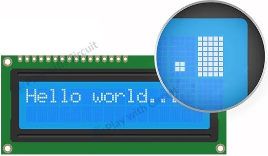
I2C LCD displays are designed specifically to display characters. For instance, a 16×2 LCD can display up to 32 ASCII characters on two rows.
As you can see in the following image, each character is formed within a tiny rectangle, consisting of a 5×8 pixel grid. Here individual pixels can be turned ON and OFF by applying voltage. By controlling different combinations of these pixels, the LCD can display different characters and symbols.
I2C LCD Adapter
It consists of following parts:
- PCF8574 Chip: It is an 8-bit I/O expander chip that converts data from the microcontroller into the parallel data required for the LCD.
- Trim-pot: A small trim-pot is available on the adapter to fine-tune the contrast of the display.
- Jumper: It has a jumper that powers the backlight. For controlling backlight intensity manually, you can remove the jumper and connect an external voltage source to the ‘LED’ pin, or add a POT to change the brightness of the LED.

I2C LCD Display Pinout

The I2C LCD display has four pins, simplifying connections and reducing wiring complexity:
GND Ground pin should be connected to the ground of Arduino or external power source.
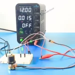
VCC It should be connected to the 5V output of the Arduino or a 5V external power supply.
SDA (Serial Data) This is an I2C data pin.
SCL (Serial Clock) This is an I2C clock pin.
Circuit Diagram of I2C Adaptor

The given schematic shows a PCF8574-based I2C adapter circuit for LCD interfacing. At the core of the circuit is the PCF8574 I/O expander (U1). It has 8 quasi-bidirectional I/O pins (P0–P7). It gets data serially over I2C pins and pushes it to parallel I/O lines. The I2C lines (pins 14 and 15 of U1) of U1 are connected through pull-up resistors R4 and R5 (4.7kΩ each) to VCC. Address pins A0, A1, and A2 of the U1 can be configured via jumpers that allow the use of multiple I2C devices on the same bus.
The LCD can be connected through a 16-pin connector (J1), with data lines (P0–P7) from the PCF8574. We can control the contrast of the LCD by a variable resistor RV1 (10kΩ). Here, we use transistor Q1 (S9013) to switch the LCD backlight ON/OFF which is controlled by the U1. Jumper JP1 enables/disables the backlight of LCD by switching power at pin 15 of J1. I/O pin P3 is used to controls the base of transistor Q1 which controls the GND at pin 16 of the connector J1.
An SMD LED (D1) along with R7 (1kΩ) acts as a power indicator, while C1 (100nF) is used for power line decoupling, improving stability. The connector J2 is used for I2C communication and power supply to the adapter.
LCD Interfacing with J1
| J1 Connector Pin | LCD Pin | Description |
|---|---|---|
| 1 | GND | Ground |
| 2 | VCC | +5V |
| 3 | V0 | Contrast (via RV1) |
| 4 | RS | Register Select (from PCF8574) |
| 5 | RW | Read/Write Select (from PCF8574) |
| 6 | EN | Enable (from PCF8574) |
| 7–14 | D0–D7 | Only D4–D7 are used (4-bit mode) (from PCF8574) |
| 15 | LED+ | Backlight + (Controlled through JP1) |
| 16 | LED- | Backlight - (Controlled through Q1) |
I2C Address of LCD
When you connect multiple I2C devices (like sensors, LCDs, etc.) to a single microcontroller on a single bus, each device must have a unique I2C address otherwise they will conflict.
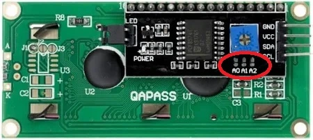
The PCF8574 chip is used to configure the addresses. It has 3 address selection pins: A0, A1, and A2. These pins can be either HIGH (1) or LOW (0), giving 8 different address combinations (2³ = 8).
The PCF8574 chip communicates over the I2C protocol using a 7-bit address which is made up of:
- 4 fixed bits set by the manufacturer.
- 3 configurable address selection bits: A2, A1, A0 that you can control to make the device address unique.

These pins are pulled HIGH by default (via 10k pull-up resistors on the adapter). If you leave all jumpers unconnected, the default address is 0x27. If you short any jumper (with solder), it pulls that pin LOW (0). This gives an address range from 0x20 to 0x27.
The following table shows different I2C addresses:

Interfacing an I2C LCD Display with Arduino
Let’s explore how to connect an I2C LCD with Arduino UNO.
Hardware Requirement
Software Requirement
- Arduino IDE, Version 2.3.4 or above installed on your PC.
- LiquidCrystal_I2C Library by Frank de Brabander V 1.1.2
Wiring Connections
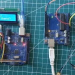
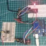
Connecting an I2C LCD to an Arduino UNO is very simple. First we connect the VCC pin of the I2C LCD module to the 5V of the Arduino and the GND pin is connected to the Arduino’s ground. Next we connect SDA (Serial Data Line) and SCL (Serial Clock Line) pins of LCD to SDA and SCL pins of Arduino. SCL and SDA pins are the same as Analog input pins A5 and A4 of Arduino where pink and blue wires are connected with LCD. These header pins are also connected to A5 and A4 pins of Arduino.
Hence when using the I2C peripheral of Arduino, do not use Analog input functionality at pin A4 or A5 pin. Make sure A0, A1, A2 address jumpers are not shorted when using I2C LCD. As in code we will be using Address 0x27 for the I2C LCD which will only be formed when these jumpers are not shorted in the I2C LCD. When all of these pins are shorted the address will become 0x20.
The following circuit diagram shows how to wire LCD to Arduino:

Installing Library for Arduino Code
Before writing a sketch to control an I2C LCD, we need to install the LiquidCrystal_I2C library. This library simplifies the code and makes it much easier to display text on your I2C LCD.
Here we will use the LiquidCrystal_I2C library developed by Frank de Brabander.
Steps to install the library in Arduino IDE
- First open Arduino IDE .
- Then go to Library Manager and search “LiquidCrystal I2C Frank de Brabander”.
- Now Install “LiquidCrystal I2C” library.

Commonly Used Functions of LiquidCrystal I2C library
lcd.clear() clears all text from the LCD screen and resets the cursor to the home position.
lcd.cursor() function displays an underscore (_) at the cursor’s location that indicates where the next character will appear.
lcd.noCursor() hides the underscore cursor.
lcd.blink() displays a blinking block-style cursor.
lcd.noBlink() turns OFF the blinking cursor.
lcd.display() turns ON the LCD screen, showing all current characters and cursor.
lcd.noDisplay() turns OFF the LCD screen, but keeps all data intact in memory.
lcd.scrollDisplayLeft() scrolls everything (text and cursor) one space to the left.
lcd.scrollDisplayRight() scrolls everything one space to the right.
lcd.backlight() initializes the LCD screen.
lcd.init() turns ON the LCD backlight.
Determining the I2C Address
Before connecting your I2C LCD with Arduino, it’s important to know the LCD’s I2C address to communicate with it correctly. While many I2C LCD modules have 0x27 as the default address, that’s not always the case. To avoid communication errors, it’s best to confirm the exact I2C address of your module. The easiest way to do this is by uploading a simple I2C Scanner sketch to your Arduino. It will automatically print the LCD address to the Serial Monitor.
Arduino Code for Finding I2C Address
This Arduino code is detects and displays the I2C address of an LCD module. It scans all possible I2C addresses, finds the correct one, and then displays it both on the serial monitor and on the LCD screen itself.
Upload the following code to your Arduino:
/*
Code to display LCD's own address on I2C LCD
by www.playwithcircuit.com
*/
#include <Wire.h>
#include <LiquidCrystal_I2C.h>

LiquidCrystal_I2C lcd(0x27, 16, 2); // 0x27 is the Default address, will reinitialize later with correct address

void setup() {
  Wire.begin();
  Serial.begin(9600);

  byte lcdAddress = 0;
  Serial.println("Scanning for I2C devices...");

  // Scan for I2C devices
  for (byte address = 1; address < 127; address++) {
    Wire.beginTransmission(address);
    if (Wire.endTransmission() == 0) {
      lcdAddress = address;
      Serial.print("I2C device found at 0x");
      Serial.println(address, HEX);
      break; // Take the first device found (LCD expected)
    }
  }

  if (lcdAddress == 0) {
    Serial.println("No I2C device found.");
    while (1); // Halt if nothing found
  }

  // Initialize LCD with found address
  LiquidCrystal_I2C lcd(lcdAddress, 16, 2);
  lcd.init();
  lcd.backlight();

  // Display the address on the LCD
  lcd.setCursor(0, 0);
  lcd.print("My Address is:");
  lcd.setCursor(0, 1);
  lcd.print("0x");
  if (lcdAddress < 16) lcd.print("0"); // Add leading zero if needed
  lcd.print(lcdAddress, HEX);
}

void loop() {
  // Nothing here
}
Once you’ve uploaded the above sketch to your Arduino, the LCD will display the address of your I2C LCD on the screen.
Output

Make a note of this address—you’ll need it when initializing the LCD in your Arduino code.
Code Explanation
This sketch begins by including two essential libraries: Wire.h (for I2C communication) and LiquidCrystal_I2C.h (to control the LCD over I2C). Now we create an LCD object with I2C address of 0x27, with a 16-column and 2-row display.
#include <Wire.h>
#include <LiquidCrystal_I2C.h>
LiquidCrystal_I2C lcd(0x27, 16, 2);
In the setup() function, the code starts the I2C communication with Wire.begin() and initializes the serial monitor at a baud rate of 9600 using Serial.begin(9600).
void setup() {
  Wire.begin();
  Serial.begin(9600);
The loop scans the entire range of possible 7-bit I2C addresses (from 0x01 to 0x7E). For each address, it tries to initiate a transmission. If Wire.endTransmission() returns 0, it means a device has acknowledged the communication — confirming that an I2C device exists at that address. The first detected address is stored in lcdAddress and displayed in hexadecimal format in the serial monitor.
byte lcdAddress = 0;
  Serial.println("Scanning for I2C devices...");
  // Scan for I2C devices
  for (byte address = 1; address < 127; address++) {
    Wire.beginTransmission(address);
    if (Wire.endTransmission() == 0) {
      lcdAddress = address;
      Serial.print("I2C device found at 0x");
      Serial.println(address, HEX);
      break; // Take the first device found (LCD expected)
    }
  }
If no device responds during the scan, the variable lcdAddress remains zero. In that case, the program prints a message and halts using an infinite while loop. This prevents the rest of the code from executing, avoiding errors due to an undefined LCD address.
if (lcdAddress == 0) {
    Serial.println("No I2C device found.");
    while (1); // Halt if nothing found
  }
Once the valid I2C address is found, a new LiquidCrystal_I2C object is created using the correct lcdAddress. Then lcd.init() initializes the display, and lcd.backlight() turns on the backlight so the text is visible.
// Initialize LCD with found address
  LiquidCrystal_I2C lcd(lcdAddress, 16, 2);
  lcd.init();
  lcd.backlight();
Now, the LCD is ready to show the message. The cursor is set to the top row using lcd.setCursor(0, 0) and prints “My Address is:”. Then on the second row, it prints “0x” followed by the detected address in hexadecimal format. If the address is less than 0x10, a leading zero is added to maintain a two-digit hex format like 0x03 or 0x0A.
// Display the address on the LCD
  lcd.setCursor(0, 0);
  lcd.print("My Address is:");
  lcd.setCursor(0, 1);
  lcd.print("0x");
  if (lcdAddress < 16) lcd.print("0"); // Add leading zero if needed
  lcd.print(lcdAddress, HEX);
}
Arduino Code
In this Arduino sketch, we’ll print “Hello” on the first line and “PlayWithCircuit” on the second line of the 16×2 LCD display.
/*
Code to display Strings on I2C LCD
by www.playwithcircuit.com
*/

#include <LiquidCrystal_I2C.h>

LiquidCrystal_I2C lcd(0x27, 16, 2); // Format -> (Address,Width,Height )

void setup()
{
  // initialize the lcd
  lcd.init();
  // Turn on the Backlight
  lcd.backlight();
}

void loop()
{
  // Clear the display buffer
  lcd.clear();
  // Set cursor (Column, Row)
  lcd.setCursor(0, 0);
  // print "Hello" at (0, 0)
  lcd.print("Hello");
  // Set cursor (Column, Row)
  lcd.setCursor(0,1);
  // print "PlayWithCircuit" at (0, 1)
  lcd.print("PlayWithCircuit");
  while(1);
}
Code Explanation
First we include the LiquidCrystal_I2C.h library which provides all the functions required to control an LCD display using the I2C protocol.
#include <LiquidCrystal_I2C.h>Then we create an lcd object with:
- 0x27: The I2C address of the LCD module.
- 16: Number of columns (characters per row)
- 2: Number of rows.
LiquidCrystal_I2C lcd(0x27, 16, 2); // Format -> (Address, Width, Height )In the setup function we call two functions,
lcd.init()initializes the communication between the Arduino and the LCD.lcd.backlight()ON the LED backlight of the LCD.
void setup()
{
  // initialize the lcd
  lcd.init();
  // Turn on the Backlight
  lcd.backlight();
}
In the loop function, first we clear the display using lcd.clear().
void loop()
{
  // Clear the display buffer
  lcd.clear();
Then we position the cursor at column 0, row 0 (first row, first column) using lcd.setCursor(0, 0). Note that the top-left corner is (0, 0) and bottom-left is (0, 1) on a 16×2 display.
 // Set cursor (Column, Row)
  lcd.setCursor(0, 0);
Next we displays the word “Hello” starting from position (0, 0) using lcd.print("Hello"). After that the cursor is moved to the second row (0, 1) using lcd.setCursor(0, 1).
  // print "Hello" at (0, 0)
  lcd.print("Hello");
  // Set cursor (Column, Row)
  lcd.setCursor(0,1);
Next we display “PlayWithCircuit” starting from the beginning of the second line using lcd.print(“PlayWithCircuit”).
Then we use while(1) to halt the program. Without it, the LCD would continuously clear and rewrite the same text, leading to flickering.
  lcd.print("PlayWithCircuit");
  while(1);
}
💡Must Read
Interfacing 16×2 LCD with Arduino Uno
This article explains how to interface a 16×2 LCD with an Arduino UNO and how to display custom characters on the LCD.
How to Create and Display Custom Characters on an I2C LCD
With a 16×2 LCD that uses HD44780 driver, you’re not limited to just the standard alphabets, numbers, and symbols. You can also design and display your own custom characters, such as a smiley face, a heart, an arrow or arms up. It can hold up to 8 custom characters in its CGRAM.
As we discussed earlier, each character you see on the LCD is displayed using a 5×8 dot matrix grid. To create a custom character you have to determine which of these tiny squares (pixels) should be turned ON or OFF.
To create a new character:
- You need to define an array of 8 bytes in your code because there are 8 rows of pixels.
- Each byte represents one row of the character, starting from the top to bottom.
- Only the first 5 bits of each byte are used (since the character is 5 pixels wide).
- ‘1’ turns a pixel ON, and a ‘0’ turns it OFF.
Once your character array is ready, you can use the createChar() function to store it in the LCD’s CGRAM. Each character is assigned a slot (from 0 to 7), and once it’s in memory, you can display it on the screen using lcd.write().
Memory Types: CGROM vs. CGRAM
The LCD controller has two types of memory that store characters:
CGROM (Character Generator ROM): CGROM stands for Character Generator Read-Only Memory. It’s a non-volatile memory which means the data stored in it is permanent, even when your LCD or Arduino is powered off.
In CGROM predefined character patterns are stored—like standard ASCII alphabet (A–Z), numbers (0–9), punctuation marks, and some symbols (like #, @, etc.).
CGRAM (Character Generator RAM): CGRAM stands for Character Generator Random Access Memory. It’s volatile memory, so any data stored in it will be lost when the power goes OFF or the Arduino resets.
Here you can store your custom characters. However CGRAM has only 64 bytes total, so you can store 8 custom characters for 5×8 displays.
Custom Character Generator
Designing custom characters for your LCD just got a whole lot simpler! With our Custom Character Generator tool, you can easily create a smiley face, a heart, an arrow, or any character that can fit in the grid.
The tool has a 5×8 grid that represents the pixel layout of a character on an LCD. All you need to do is click on the squares (pixels) to turn them ON or OFF. As you draw your character on the grid, the array for the custom character is automatically generated right next to it, which can later be used in your Arduino code as it is.
Arduino Code for Displaying Custom Characters
This Arduino Sketch display custom characters on LCD screen.
/*
Code to display custom characters on I2C LCD
by www.playwithcircuit.com
*/
#include <LiquidCrystal_I2C.h>

// Initialize LCD at default I2C address 0x27, 16x2 display
LiquidCrystal_I2C lcd(0x27, 16, 2);

// Custom Characters
byte smiley[8] = {
  0b00000,
  0b00000,
  0b01010,
  0b00000,
  0b00000,
  0b10001,
  0b01110,
  0b00000
};

byte armsUp[8] = {
  0b00100,
  0b01010,
  0b00100,
  0b10101,
  0b01110,
  0b00100,
  0b00100,
  0b01010
};

byte face[8] = {
  0b11111,
  0b10001,
  0b00000,
  0b01010,
  0b00000,
  0b00100,
  0b00000,
  0b01110
};

char u8Buffer[17]="Smile ArmUp Face";

void setup() {
  lcd.init();       // Initialize the LCD
  lcd.backlight();   // Turn on the backlight

  // Create custom characters
  lcd.createChar(0, smiley);
  lcd.createChar(1, armsUp);
  lcd.createChar(2, face);

  // Display custom characters on LCD
  lcd.setCursor(0, 0);
  for(int i=0; i < 17; i++){
    lcd.print(u8Buffer[i]);
    delay(100);
  }

  lcd.setCursor(0, 1);
  lcd.write(byte(0)); // smiley
  lcd.print("       ");
  delay(300);
  lcd.write(byte(1)); // armsUp
  lcd.print("      ");
  delay(300);
  lcd.write(byte(2)); // face
}

void loop() {
  // Nothing in loop
}
Output

Code Explanation
First we include the LiquidCrystal_I2C library and create an LCD object same as above code.
#include <LiquidCrystal_I2C.h>

// Initialize LCD at default I2C address 0x27, 16x2 display
LiquidCrystal_I2C lcd(0x27, 16, 2);
Now we create custom characters. The following arrays define 8 custom character patterns using 8 bytes. Each byte uses 5 bits (the least significant) to control which pixels are ON (1) or OFF (0) in that row. For example, 0b01010 in the smiley pattern lights up the 2nd and 4th pixels in that row to resemble eyes. The LCD controller allows for storing up to 8 custom characters (indexed 0–7) in its CGRAM.
// Custom Characters
byte smiley[8] = {
  0b00000,
  0b00000,
  0b01010,
  0b00000,
  0b00000,
  0b10001,
  0b01110,
  0b00000
};

byte armsUp[8] = {
  0b00100,
  0b01010,
  0b00100,
  0b10101,
  0b01110,
  0b00100,
  0b00100,
  0b01010
};

byte face[8] = {
  0b11111,
  0b10001,
  0b00000,
  0b01010,
  0b00000,
  0b00100,
  0b00000,
  0b01110
};
Next we define a character array (char) of size 17 to store a simple message: “Smile ArmUp Face”.
char u8Buffer[17]="Smile ArmUp Face";The setup() function runs once when the Arduino powers on. First, we initialize the communication between the Arduino and the I2C LCD. Next, we turn ON the LCD’s backlight.
void setup() {
  lcd.init();       // Initialize the LCD
  lcd.backlight();   // Turn on the backlight
Now the predefined custom character arrays (smiley, armsUp, and face) are loaded into the LCD’s CGRAM at positions 0, 1, and 2.
// Create custom characters
  lcd.createChar(0, smiley);
  lcd.createChar(1, armsUp);
  lcd.createChar(2, face);
Now we print the message stored in u8Buffer to the first row of the LCD, one character at a time. Then we move the cursor to the top-left corner of the LCD (column 0, row 0).
The for loop iterates through each character in u8Buffer and prints it with a delay(100) between each character. This creates a simple typing animation, making the text appear letter-by-letter instead of all at once.
 // Display custom characters on LCD
  lcd.setCursor(0, 0);
  for(int i=0; i < 17; i++){
    lcd.print(u8Buffer[i]);
    delay(100);
  }
Now that the first row has the text, we update the second row with the custom characters. First, lcd.setCursor() moves the cursor to the beginning of the second row. Then, it writes the custom characters at positions 0, 1, and 2. Then spaces are added after each character to separate them visually and maintain alignment. Small delays between each character make the output easy to view step-by-step.
  lcd.setCursor(0, 1);
  lcd.write(byte(0)); // smiley
  lcd.print("       ");
  delay(300);
  lcd.write(byte(1)); // armsUp
  lcd.print("      ");
  delay(300);
  lcd.write(byte(2)); // face
}
Arduino Code for Displaying Animation on I2C LCD
This sketch illustrates how to simulate a progress bar animation using partial characters.
/*
Code to display Animation of Progress Bar on I2C LCD
by www.playwithcircuit.com
*/
#include <LiquidCrystal_I2C.h>

// Init LCD at 0x27, 16x2
LiquidCrystal_I2C lcd(0x27, 16, 2);

// Custom characters for partial blocks (1/5 to full)
byte bar1[8] = { 0b10000, 0b10000, 0b10000, 0b10000, 0b10000, 0b10000, 0b10000, 0b10000 };
byte bar2[8] = { 0b11000, 0b11000, 0b11000, 0b11000, 0b11000, 0b11000, 0b11000, 0b11000 };
byte bar3[8] = { 0b11100, 0b11100, 0b11100, 0b11100, 0b11100, 0b11100, 0b11100, 0b11100 };
byte bar4[8] = { 0b11110, 0b11110, 0b11110, 0b11110, 0b11110, 0b11110, 0b11110, 0b11110 };
byte bar5[8] = { 0b11111, 0b11111, 0b11111, 0b11111, 0b11111, 0b11111, 0b11111, 0b11111 };

void setup() {
  lcd.init();
  lcd.backlight();

  // Create Custom Characters at CGRAM Slots 0–4
  lcd.createChar(0, bar1);
  lcd.createChar(1, bar2);
  lcd.createChar(2, bar3);
  lcd.createChar(3, bar4);
  lcd.createChar(4, bar5);

  lcd.setCursor(0, 0);
  lcd.print("Progress:");
}

void loop() {
  const int barLength = 10;  // 10 full LCD columns for bar
  for (int percent = 0; percent <= 100; percent++) {
    // Calculate number of full blocks and remaining pixels
    int totalBars = (percent * barLength * 5) / 100;  // total 1/5 units
    int fullBlocks = totalBars / 5;
    int remainder = totalBars % 5;

    // Draw the progress bar
    lcd.setCursor(0, 1);
    for (int i = 0; i < barLength; i++) {
      if (i < fullBlocks) {
        lcd.write(byte(4)); // full block
      } else if (i == fullBlocks && remainder > 0) {
        lcd.write(byte(remainder - 1)); // partial block (0–3)
      } else {
        lcd.print(" "); // empty space
      }
    }

    // Display percentage
    lcd.setCursor(11, 1);
    lcd.print(percent);
    lcd.print("% ");
    delay(100);
  }

  delay(1000); // Hold at 100% before resetting
  lcd.setCursor(0, 1);
  lcd.print("                "); // Clear line
}
Output
Code Explanation
First we include LiquidCrystal_I2C library then initializes the LCD at I2C address 0x27, with 16 columns and 2 rows.
#include <LiquidCrystal_I2C.h>

// Init LCD at 0x27, 16x2
LiquidCrystal_I2C lcd(0x27, 16, 2);
The LCD can store 8 custom characters in its CGRAM (Character Generator RAM). Each byte barX[8] array defines a custom character that looks like a horizontal bar — starting from just a small segment (1/5th) and going all the way to a full block.
byte bar1[8] = { 0b10000, 0b10000, 0b10000, 0b10000, 0b10000, 0b10000, 0b10000, 0b10000 };
byte bar2[8] = { 0b11000, 0b11000, 0b11000, 0b11000, 0b11000, 0b11000, 0b11000, 0b11000 };
byte bar3[8] = { 0b11100, 0b11100, 0b11100, 0b11100, 0b11100, 0b11100, 0b11100, 0b11100 };
byte bar4[8] = { 0b11110, 0b11110, 0b11110, 0b11110, 0b11110, 0b11110, 0b11110, 0b11110 };
byte bar5[8] = { 0b11111, 0b11111, 0b11111, 0b11111, 0b11111, 0b11111, 0b11111, 0b11111 };
In the setup function first we initialize the LCD module. Then turn on the LCD’s backlight.
lcd.createChar() function lets you create your own custom characters on the LCD.
We save custom block shapes (stored in bar1 to bar5) into the LCD’s memory (CGRAM). 0–4 are slots where these characters are stored. bar1 is a small block, bar5 is a full block that is used to animate the progress bar.
Next, the cursor is moved to the top-left corner of the screen. Then it prints “Progress:” on the first row (0-indexed) to label the progress bar.
void setup() {
  lcd.init();
  lcd.backlight();

  // Create Custom Characters at CGRAM Slots 0–4
  lcd.createChar(0, bar1);
  lcd.createChar(1, bar2);
  lcd.createChar(2, bar3);
  lcd.createChar(3, bar4);
  lcd.createChar(4, bar5);

  lcd.setCursor(0, 0);
  lcd.print("Progress:");
}
In the loop function, we set the length of the progress bar to 10 columns (characters) on the LCD.
Each time the loop runs, it represents a new frame of the animation. So, the bar starts completely empty at 0%, and it slowly fills up to 100%.
void loop() {
  const int barLength = 10;  // 10 full LCD columns for bar
  for (int percent = 0; percent <= 100; percent++) {
This following part does the math to figure out how many blocks should be filled based on the current percent value.
totalBars gives us the progress in “1/5th units” (because each character can show 5 levels of fill). fullBlocks tells us how many complete blocks we need to fill. remainder tells us how much of the next block needs to be partially filled.
// Calculate number of full blocks and remaining pixels
    int totalBars = (percent * barLength * 5) / 100;  // total 1/5 units
    int fullBlocks = totalBars / 5;
    int remainder = totalBars % 5;
Now the bar is drawn on the second row of the LCD. It runs through each of the 10 positions of the bar (from 0 to 9):
- If the index i is less than fullBlocks, we display a full block character (custom char at CGRAM slot 4).
- If we’re at the position where a partial block should be shown (i == fullBlocks), we show the appropriate partial bar from CGRAM using lcd.write(byte(remainder – 1)). For example, if the remainder is 3, then it displays a character that looks like 3/5 filled.
- For all the remaining positions, we simply print a blank space to indicate that the portion of the bar hasn’t been filled yet.
  // Draw the progress bar
    lcd.setCursor(0, 1);
    for (int i = 0; i < barLength; i++) {
      if (i < fullBlocks) {
        lcd.write(byte(4)); // full block
      } else if (i == fullBlocks && remainder > 0) {
        lcd.write(byte(remainder - 1)); // partial block (0–3)
      } else {
        lcd.print(" "); // empty space
      }
    }
After the bar is drawn, the percentage is printed to the right of the bar (starting at column 11). The short pause of 100 milliseconds slows down the loop just enough to make the progress animation visible and smooth.
// Display percentage
    lcd.setCursor(11, 1);
    lcd.print(percent);
    lcd.print("% ");
    delay(100);
  }
Once the loop hits 100%, the program pauses for one second so the user can see the completed progress bar. After that, we clear the second line, resetting the display for the next cycle.
delay(1000); // Hold at 100% before resetting
  lcd.setCursor(0, 1);
  lcd.print("                "); // Clear line
}


