
A bench power supply is one of the most important tools on an electronics workbench. Unlike batteries or fixed adapters, it allows safe testing and a deeper understanding of how circuits behave under real operating conditions. In this article, we would like to share our experiences of using the SPS-3010V variable DC bench power supply.
Overview of the Jesverty SPS-3010V
The Jesverty SPS-3010V is a regulated DC bench power supply capable of delivering 0 to 30 volts and up to 10A of current. This range comfortably covers most low-voltage electronics work from logic circuits to small motors and power modules.
Unlike fixed adapters, this unit operates in two fundamental regulation modes:
Constant Voltage Mode (CV): In CV mode, the power supply maintains a fixed output voltage. The connected circuit draws as much current as it needs within the supply limit. As long as the current stays below the set limit, the voltage remains stable.
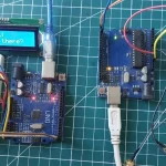
This mode is typically used when powering Arduino and ESP boards, logic circuits, sensor modules, pre-designed electronic boards.
Constant Current Mode (CC): In CC mode, the power supply limits the maximum current. If the circuit tries to draw more current than allowed, the supply automatically reduces the voltage to keep the current constant.
This mode is extremely useful for protecting new circuits, testing unknown loads, powering LEDs and learning how load resistance affects voltage.
Technical Specifications
| Output Voltage Range | 0-30V |
| Output Current Range | 0-10A |
| Output Wattage | 320 Watts |
| Voltage Resolution | 0.01V |
| Current Resolution | 0.001A |
| Display Type | 4-Digit Seven Segment LED Display |
| USB Ports | 1x USB-A, 1x USB-C (20W Quick-Charge each) |
| Input Voltage | AC115V/230V (Selectable) |
Package Contents
Inside the box, you will find the main power supply unit, an AC input power cable, an output power cable set, and a user manual. Jesverty also mentions to provide lifetime technical support. This unit also includes output leads, typically with banana plugs on one end and alligator clips on the other.
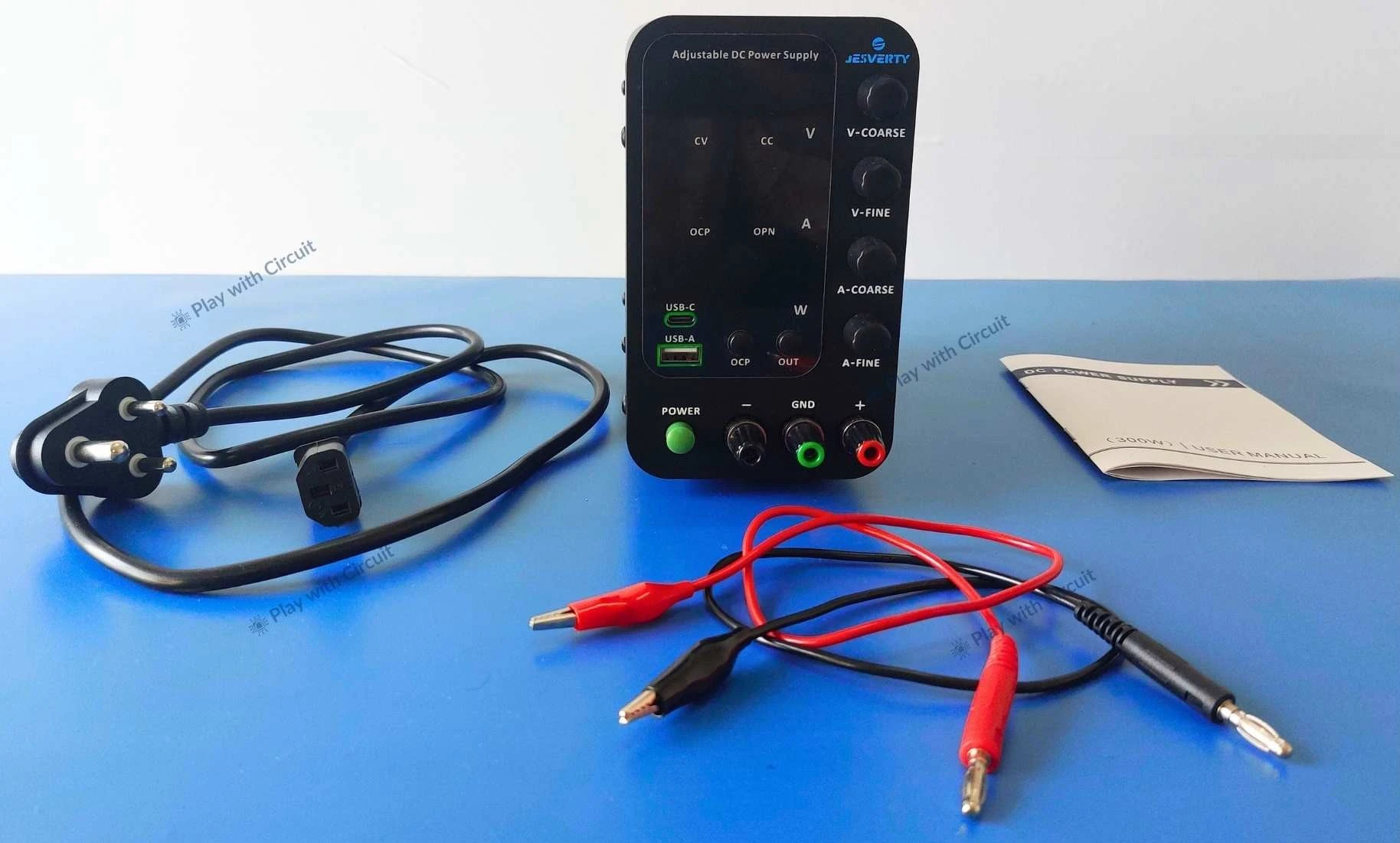
These leads are helpful for first-time users, as they allow immediate testing without purchasing additional accessories. However, for higher current applications, thicker and more robust leads may be preferable to minimize voltage drop and heating.
First Impression and Build Quality
The SPS-3010V feels compact and it doesn’t take up excessive bench space, which is important when working with breadboards, tools, and test instruments nearby. The enclosure feels reasonably solid for a switching-mode supply in this category. The metal enclosure adds structural rigidity to the unit, preventing any noticeable flex during handling.
Front Panel Layout and User Controls
The front panel of the Jesverty SPS-3010V has a beginner-friendly design. At the top a bright 4 digit LED digital display shows output voltage, output current, and calculated power (watts). These displays update in real time, allowing you to immediately see how your circuit behaves as soon as it is connected.
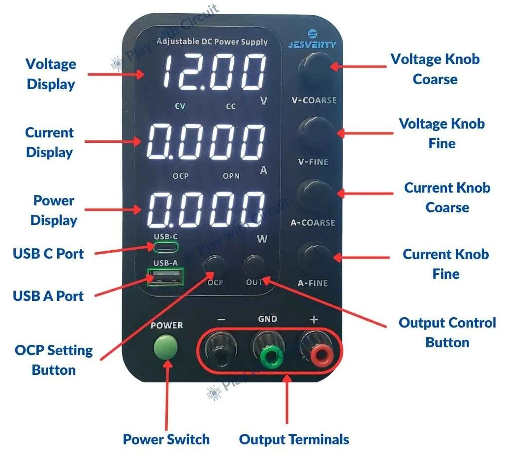
Just below the Voltage display are status indicators that show whether the power supply is operating in Constant Voltage (CV) or Constant Current (CC) mode.
It also features separate coarse and fine adjustment knobs for both voltage and current. The coarse adjustment knobs allow you to move quickly through the voltage or current range. This is useful when you want to increase voltage quickly. Once you are close to your desired value, the fine adjustment knobs allow precise tuning, such as setting exactly 5 V or 3.3 V for microcontroller boards. This two-stage adjustment system is especially helpful when working with sensitive electronics, where small voltage changes can make a significant difference. The adjustment also feels smooth and predictable.
The front panel also includes clearly marked positive (+), negative (–), and ground terminals. These terminals support banana plugs as well as bare wire connections, giving flexibility depending on the type of project.
The included banana-to-alligator leads make it easy to connect components such as resistors, motors, lamps, and prototype circuits during testing.
In addition to the main DC output terminals, the power supply includes a 5V USB output port on the front panel. This port can be used to power or charge small devices, such as smartphones or development boards.
The main power switch is conveniently located on the front panel, allowing you to turn the unit ON and OFF. It improves safety and convenience, especially when frequently connecting and disconnecting loads.
Rear Panel Layout and Power Input Design
The rear panel of the Jesverty SPS-3010V includes a selectable 110V / 220V AC input switch allowing the unit to be used in different regions. Next to the AC input socket, there is a replaceable fuse, which provides an additional layer of protection against overcurrent or internal faults. This is a simple but important safety feature, especially in home labs.
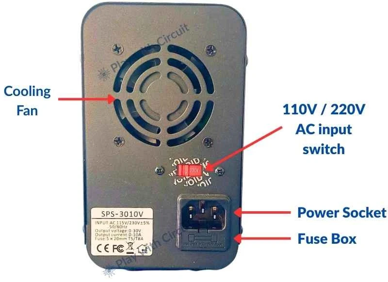
Cooling is handled by an internal temperature-controlled fan located at the rear. It briefly spins at power-up and then remains off until the internal temperature reaches a predefined threshold. This design reduces unnecessary noise during low-power operation. Ventilation slots are distributed across the rear, bottom, and side panels, allowing airflow to pass through the internal heat sinks efficiently.
Power-On Behavior and Safety
When powered on, the supply does not immediately energize the output, which is a critical safety feature. This allows time to set voltage, set current limit and double-check connections.
Only after pressing the output button, power reaches the terminals. This reduces the chance of accidentally damaging components during setup.
Output ON/OFF Control and Startup Safety
One feature that improves overall safety is the dedicated Output ON/OFF button. It allows voltage and current settings to be adjusted while the output remains disabled, preventing accidental power application during setup.
The manual also mentions an output status (OPN) behavior, which determines whether the output is enabled automatically on power-up. Keeping the output OFF by default is particularly useful in learning environments or shared labs, as it avoids unintentionally powering a connected circuit when the unit is switched on.
Over-Current Protection (OCP): How It Differs from Current Limiting
In addition to standard constant current operation, the SPS-3010V includes an Over-Current Protection (OCP) function. While current limiting reduces voltage to maintain a safe current level, OCP goes a step further by cutting off the output entirely when the set current threshold is exceeded.
Testing the DC power supply
Let’s do some tests to check the functions of power supply.
Voltage Accuracy and Stability Testing
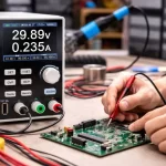
To evaluate the output voltage accuracy, we set the power supply to a value of 5V, and measure the output using a digital multimeter.
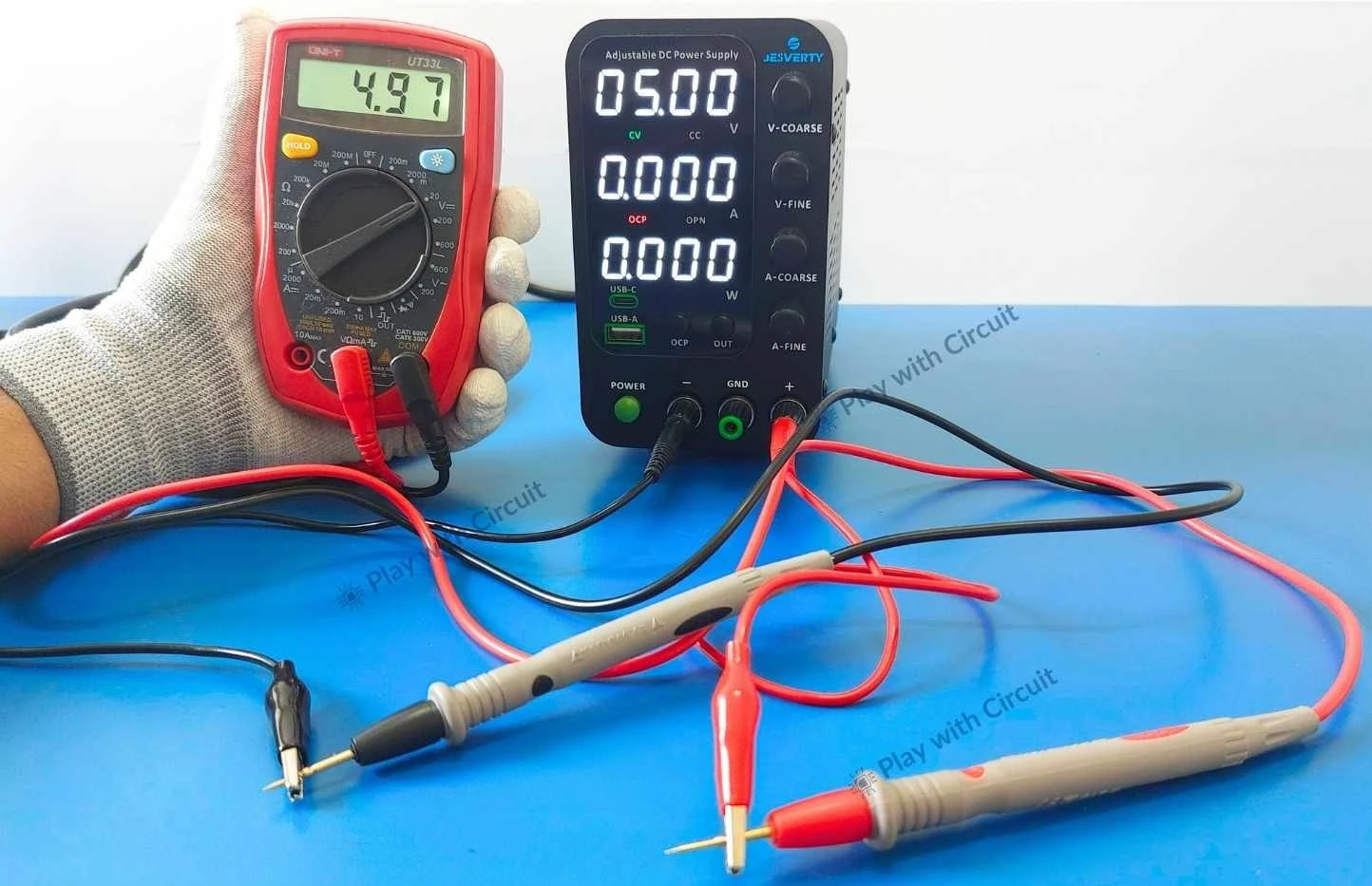
As we can see in the above image, the measured voltage is close to the set value i.e. 4.97V. This small difference is normal. Here it is to be noted that the CV (Constant Voltage) indicator is active which means the power supply is regulating the voltage.
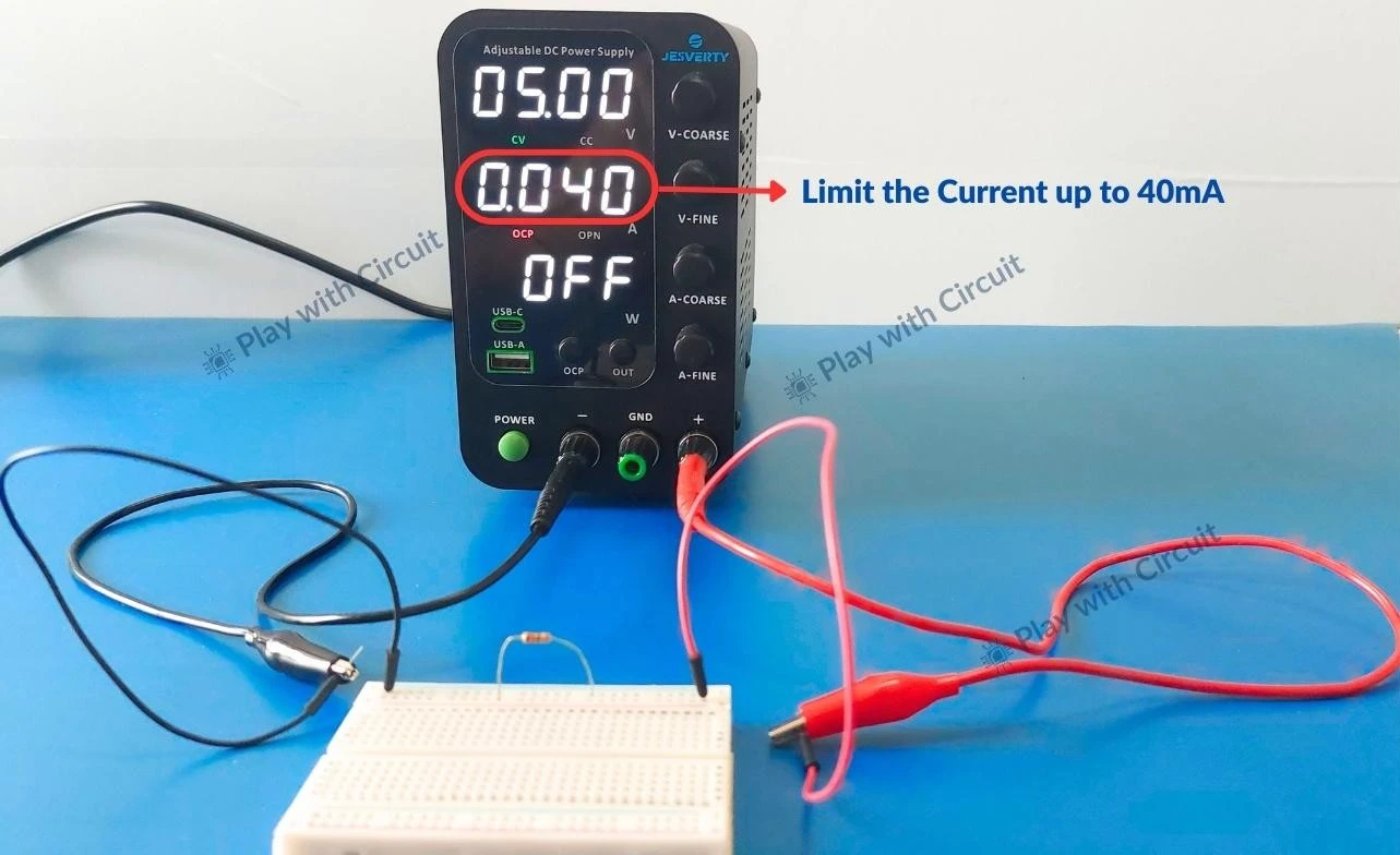
Testing Constant Current Limiting
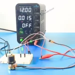
To test current limiting, we set the voltage to 5V and limit the current to 40mA. Then we connect a 120 ohm resistor.
Now we turn ON the output of the power supply. According to Ohm’s law, a 5V supply across a 220 ohm resistor should produce 22mA of current.
In real testing, the measured current is often slightly lower — for example, here it is 21mA.
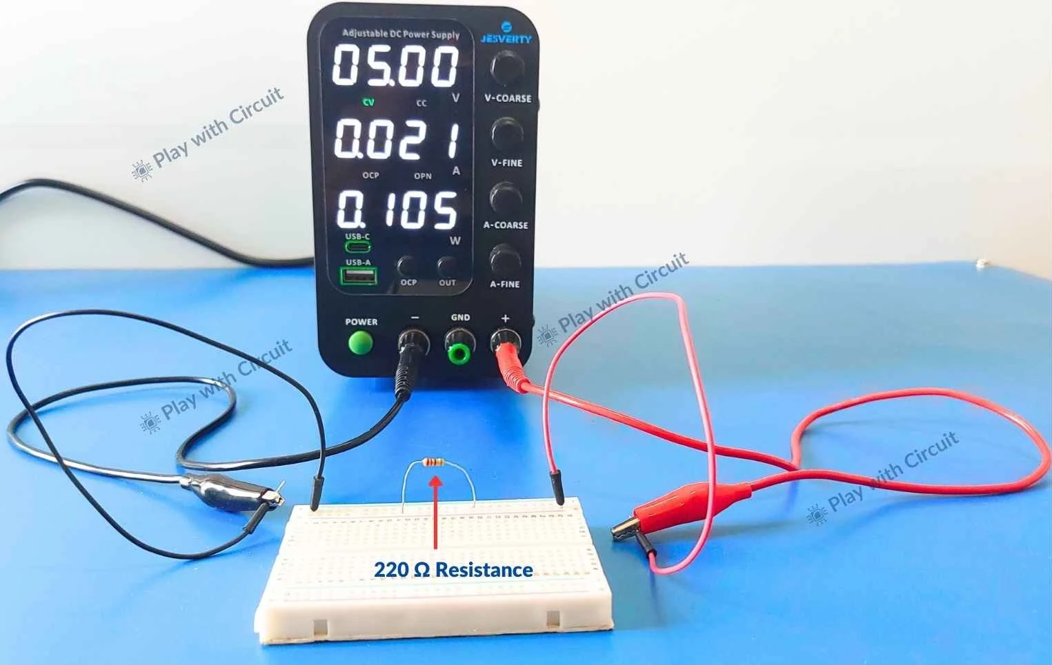
It happens because resistors have tolerance (often ±5%), their resistance increases as they heat up, and the power supply itself has internal current-sensing resistance.
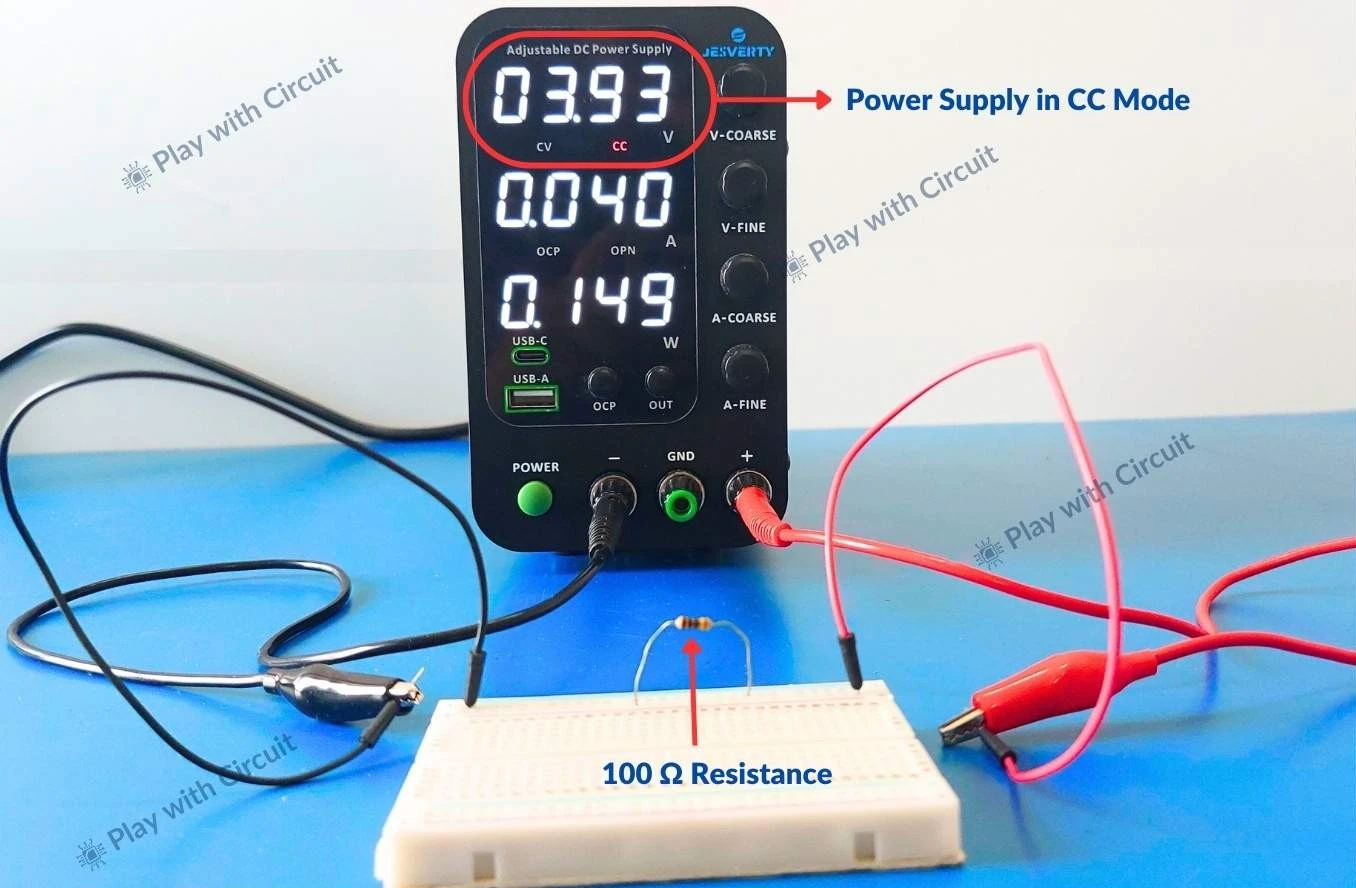
Now change the resistance to 100 ohm. According to Ohm’s law, a 5V supply across a 100-ohm resistor should produce 50mA of current.
But we have applied the limit of 40mA hence the current will be limited to 40mA and the voltage drops to around 3.93V due to current limitation.
Constant Voltage to Constant Current Mode Transition
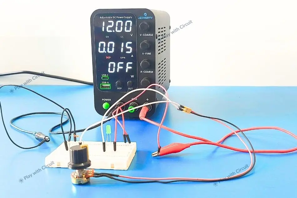
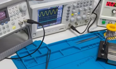
To observe how smoothly the power supply transitions between constant voltage and constant current modes, we set the voltage to 12 volt and current limit to 15mA. Now we place a 220-ohm resistance and a 10k pot in series with green LED and provide 12V to this circuit.
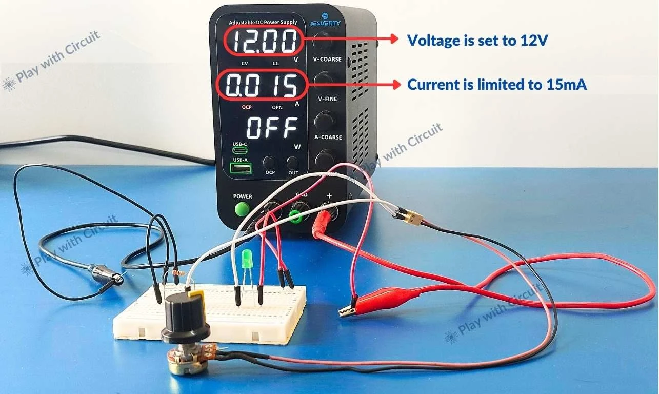
Next we turn ON the output of power supply.
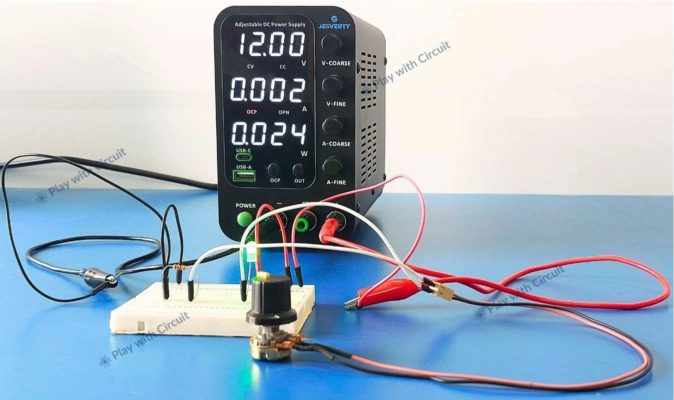
Now we decrease the resistance from 10K pot and as the current approaches the set limit, the power supply automatically transitions from constant voltage mode to constant current mode. This is clearly indicated by the CC status LED, and the output voltage began to drop while the current remained stable at the preset limit. This confirms that the power supply actively protects the load by prioritizing current control when necessary.
Testing OCP (Over Current protection)
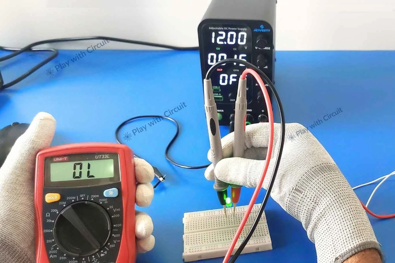
To test OCP functionality, we intentionally create a fault condition in the circuit. Let’s assume both the current-limiting resistors in the circuit fail. In such a case, excessive current could flow and damage the LED.
To prevent this, we set the OCP limit to 20mA, which is the max current an LED can handle.
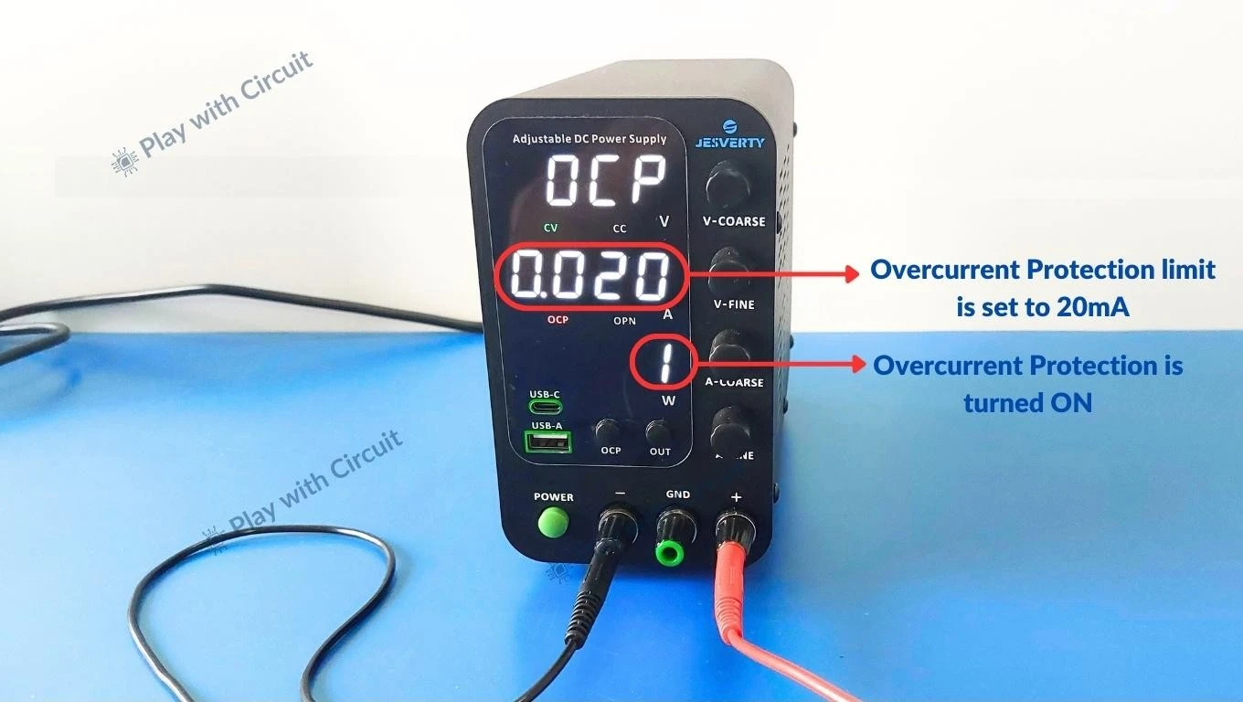
Now we simulate a fault by shorting the resistors in the circuit. This creates a low-resistance path, which would cause a large current to flow. However, since OCP is enabled, the power supply detects extra current and immediately limits or cuts off the output. In the following video, we can see the OCP indicator LED on the power supply starts blinking (red)
This indicates that the protection mechanism is active.
Now after observing OCP activation, we remove the short path and turn the output ON by pressing the OUT button. After testing we found that LED works fine which means it remains protected due to OCP feature of supply.
Minimum and Maximum Output Range Test
To verify the full voltage range, we slowly adjust the voltage control from the lowest setting to the highest value while monitoring the output using a multimeter. Near the lower end of the range, the output voltage approached zero smoothly without sudden jumps or instability.
At the higher end, we increase the voltage toward the maximum rated output. The power supply reached close to its specified upper limit while maintaining stable output. Practically voltage increases from 0V to 32V.
Is this the Right Power Supply for You?
This power supply is a strong choice if your work involves learning electronics, prototyping and general DIY projects. It offers visibility into voltage and current behaviour. However, if your work requires ultra-low noise, RF testing, or automated control, a higher-end laboratory power supply would be more appropriate.
Bottom Line
The SPS-3010V is a dependable bench power supply that performs reliably in real-world testing, offers good control and safety features and provides excellent value for learning and prototyping environments.
You can check the current price and availability of the Jesverty SPS-3010V at Amazon.
The SPS-3010V DC Power Supply used in this article was kindly provided by Jesverty for testing and evaluation purposes. However, this review is based entirely on hands-on testing and independent observations. Jesverty did not have any influence over the content, conclusions or opinions expressed in this article.


